1
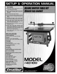
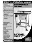
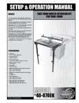
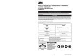
SETUP & OPERATION MANUAL
FEATURES
Router lift for Excalibur cast-iron tables
#40-070 and #40-075, MDF tables #40-047
and #40-049 & phenolic tables #40-043
and #40-045.
ROUTER LIFT
for Excalibur router tables
Heavy-duty massive router lift with 9 ¼″ x 11
¾″ aluminum top plate.
Stable 4 post/lift screw design & chain drive
lifting system controlling all 4 corners simultaneously.
MODEL
#40-125
JANUARY 03/13
© Copyright General® International 01/2013
GENERAL® INTERNATIONAL
8360 Champ-d’Eau, Montreal (Quebec) Canada H1P 1Y3
Telephone (514) 326-1161 • Fax (514) 326-5555 • www.general.ca
THANK YOU
for choosing this Excalibur by General® International model
#40-125 Router Lift. This router lift has been carefully tested and inspected before shipment and
if properly used and maintained, will provide you with years of reliable service. For your safety,
as well as to ensure optimum performance and trouble-free operation, and to get the most from
your investment, please take the time to read this manual before assembling, installing and
operating the unit.
The manual’s purpose is to familiarize you with the safe operation, basic function, and features
of this router lift as well as the set-up, maintenance and identification of its parts and components. This manual is not intended as a substitute for formal woodworking instruction, nor to
offer the user instruction in the craft of woodworking. If you are not sure about the safety of
performing a certain operation or procedure, do not proceed until you can confirm, from
knowledgeable and qualified sources, that it is safe to do so.
Once you’ve read through these instructions, keep this manual handy for future reference.
Disclaimer: The information and specifications in this
manual pertain to the unit as it was supplied from the
factory at the time of printing. Because we are committed to making constant improvements, General®
International reserves the right to make changes to
components, parts or features of this unit as deemed
necessary, without prior notice and without obligation to
install any such changes on previously delivered units.
Reasonable care is taken at the factory to ensure that
the specifications and information in this manual corres-
ponds with that of the unit with which it was supplied.
However, special orders and “after factory” modifications may render some or all information in this manual
inapplicable to your machine. Further, as several generations of this model of router lift and several versions of
this manual may be in circulation, if you own an earlier
or later version of this unit, this manual may not depict
your machine exactly. If you have any doubts or questions contact your retailer or our support line with the
model and serial number of your unit for clarification.
GENERAL® & GENERAL® INTERNATIONAL WARRANTY
All component parts of General®, General® International and Excalibur by General
International ® products are carefully inspected during all stages of production and each unit
is thoroughly inspected upon completion of assembly.
Limited Lifetime Warranty
Because of our commitment to quality and customer satisfaction, General® and General®
International agree to repair or replace any part or component which upon examination,
proves to be defective in either workmanship or material to the original purchaser for the life
of the tool. However, the Limited Lifetime Warranty does not cover any product used for professional or commercial production purposes nor for industrial or educational applications. Such
cases are covered by our Standard 2-year Limited Warranty only. The Limited Lifetime Warranty
is also subject to the “Conditions and Exceptions” as listed below.
Standard 2-Year Limited Warranty
All products not covered by our lifetime warranty including products used in commercial,
industrial and educational applications are warranted for a period of 2 years (24 months) from
the date of purchase. General® and General® International agree to repair or replace any
part or component which upon examination, proves to be defective in either workmanship or
material to the original purchaser during this 2-year warranty period, subject to the “conditions
and exceptions” as listed below.
To file a Claim
To file a claim under our Standard 2-year Limited Warranty or under our Limited Lifetime
Warranty, all defective parts, components or machinery must be returned freight or postage
prepaid to General® International, or to a nearby distributor, repair center or other location
designated by General® International. For further details call our service department at 1-888949-1161 or your local distributor for assistance when filing your claim.
Along with the return of the product being claimed for warranty, a copy of the original proof
of purchase and a “letter of claim” must be included (a warranty claim form can also be used
and can be obtained, upon request, from General® International or an authorized distributor)
clearly stating the model and serial number of the unit (if applicable) and including an explanation of the complaint or presumed defect in material or workmanship.
CONDITIONS AND EXCEPTIONS:
This coverage is extended to the original purchaser only. Prior warranty registration is not
required but documented proof of purchase i.e. a copy of original sales invoice or receipt
showing the date and location of the purchase as well as the purchase price paid, must be
provided at the time of claim.
Warranty does not include failures, breakage or defects deemed after inspection by General®
or General® International to have been directly or indirectly caused by or resulting from;
improper use, or lack of or improper maintenance, misuse or abuse, negligence, accidents,
damage in handling or transport, or normal wear and tear of any generally considered consumable parts or components.
Repairs made without the written consent of General® Internationallwill void all warranty.
Rules for Safe Operation
To help ensure safe operation, please take a moment to learn the machine’s applications and limitations, as well as potential hazards. GENERAL® INTERNATIONAL disclaims any real or implied warranty and holds itself harmless for any injury that may result from improper use of its equipment.
1. Make sure that the operator has been properly
trained and has read and understands the Owner’s
Manual before operating any machinery.
2. Be sure to read, understand and follow all instructions,
warnings and safety guidelines supplied with your
router.
3. Do not operate this router table when tired, distracted,
or under the effects of drugs, alcohol or any medication that impairs reflexes or alertness.
14. Keep all guards and safety devices in place and in
good working order. If a guard must be removed for
maintenance or cleaning make sure it is properly reinstalled before using the machine again.
4. Keep the work area well lit, clean and free of debris.
15. Hold the workpiece firmly against the table and use
suitable support if the workpiece does not have a flat
surface.
5. Stay Alert! Give your work your undivided attention.
Even a momentary distraction can lead to serious
injury.
16. Feed the stock into the bit against the rotation direction of the bit. Never run the stock between the fence
and the bit.
6. Do not wear loose clothing, gloves, bracelets, necklaces, or other jewelry. Wear face, eye, ear, respiratory
and body protection devices. Wear protective hair
covering to contain long hair and wear non-slip
footwear.
17. Do not operate with a damaged bit in the router.
7. Keep hands and other body parts well away from bits
or cutting tools. When working close to the cutting tool,
always use a feather board or push-stick to hold or
guide the workpiece. Do not clear chips and sawdust
away with hands. Use a brush.
8. Fine particulate dust is a carcinogen that can be hazardous to health. Always work in a well ventilated area
and whenever possible use a dust collector to minimize health hazards.
9. Be sure the router is running up to speed before feeding the workpiece.
10. Use a suitable support if stock does not have a flat
surface.
11. Keep children and visitors at a safe distance when the
router is in operation – do not permit them to operate
the router and table.
12. Childproof and tamper proof your shop and all
machinery with locks, master electrical switches and
switch keys, to prevent unauthorized or unsupervised
use.
4
13. Secure the table to a work surface and never stand or
lean on it. Serious injury could occur if the table is
tipped or if unintentional contact is made with spinning router bit.
18. Always disconnect the router from the power source
before changing accessories or before performing
any maintenance and adjustments or if the machine
will be left unattended.
19. Be sure that all adjustment tools, wrenches or other
clutter are removed from the table surface and safely
stored before routing.
20. Make sure the routers switch is in the “OFF” position
before plugging in to a power source.
21. Avoid working from awkward or off balance positions.
Do not overreach and always keep both feet firmly on
the floor.
22. Never leave the router unattended while running or
with the power on.
23. Do not use this router table for any purpose other than
its intended use. If used for other purposes, GENERAL®
INTERNATIONAL disclaims any real or implied warranty
and holds itself harmless for any injury which may
result from such use.
IDENTIFICATION OF MAIN PARTS AND COMPONENTS
ABCD-
CLAMPING BOLT
CLAMPING BRACKET
CHAIN
INSERT RING WRENCH
EFGH-
STARTING PIN
CRANK HANDLE
POSTS/SCREWS
LOCK NUT
UNDERSIDE VIEW
F
D
C
E
B
A
G
G
G
H
G
UNPACKING
Carefully unpack and remove the
router lift and its components from
the box and check for damaged or
missing items as per the list of contents below.
a
c
NOTE: Please report any damaged
or missing items to your General
International distributor immediately.
LIST OF CONTENTS
QTY
a- ROUTER LIFT . . . . . . . . . . . . . . . . . . . . . . . . . . .1
b
b- ROUTER LIFT CRANK HANDLE . . . . . . . . . . . . .1
c- INSERT RING WRENCH . . . . . . . . . . . . . . . . . . .1
d- STARTER PIN . . . . . . . . . . . . . . . . . . . . . . . . . . . .1
e- HEX SOCKET HEAD BOLT . . . . . . . . . . . . . . . . . .2
f- 2.5 MM ALLEN KEY . . . . . . . . . . . . . . . . . . . . . .1
g- 3 MM ALLEN KEY . . . . . . . . . . . . . . . . . . . . . . .1
d
e
h- 4 MM ALLEN KEY . . . . . . . . . . . . . . . . . . . . . . .1
i- 6 MM ALLEN KEY . . . . . . . . . . . . . . . . . . . . . . .1
f
g
h
i
5
ASSEMBLY INSTRUCTIONS - PREPARE THE TABLE * FOR ROUTER LIFT
SERIOUS PERSONAL INJURY COULD OCCUR IF YOU CONNECT THE MACHINE TO THE POWER SOURCE BEFORE YOU HAVE COMPLETED THE INSTALLATION AND ASSEMBLY STEPS. DO NOT CONNECT THE MACHINE TO THE POWER SOURCE UNTIL INSTRUCTED
TO DO SO.
* Excalibur Router Tables.
Note regarding installation on shop-made or non-Excalibur router tables: Before constructing your own table top, take note
that Excalibur does not use leveler set screws in their router plates or lifts. Instead each Excalibur router table includes it’s
own built-in leveling system. The reason for this is that on shop-made table tops made of wood or MDF, metal set screw levelers in the router plate will eventually sink into the softer material of the table and become ineffective. If you are installing
this router lift in a shop made router table or on another brand of router table that does not include a built-in levelling
sytem PLEASE SEE/USE THE EXCALIBUR #40-092 LEVELER BAR KIT DESIGNED SPECIFICALLY FOR USE WITH SHOP-
MADE TABLE TOPS.
Note: Model #40-075 for 40-200C Cast-iron table shown. The following steps apply to all Excalibur router table options.
1. Place the router lift into the opening in the table.
2. Use a straightedge to test the plate for level with the
table top.
A
3. From the underside of the table, adjust the 4 phillips
head screws in the corners A - up or down until the
plate is flat and level with the table surface.
4. Remove the lift and lock the adjuster screw in place
by turning the lock nut A clockwise (tighten).
Note: While tightening the lock nut, make sure that the
adjuster screw does not turn. Confirm by re-checking
the leveling of the lift and table surface.
6
5. After the four corners are set, proceed to set the
remaining 6 leveler screws and lock them in place.
ASSEMBLY INSTRUCTIONS - MOUNTING A ROUTER
SERIOUS PERSONAL INJURY COULD OCCUR IF YOU CONNECT THE MACHINE TO THE POWER SOURCE BEFORE YOU HAVE COMPLETED THE INSTALLATION AND ASSEMBLY STEPS. DO NOT CONNECT THE MACHINE TO THE POWER SOURCE UNTIL INSTRUCTED
TO DO SO.
This model 40-125 “fixed base” router lift, A is designed to
accommodate the largest diameter router motor body
currently available.
B
Note: Based on our research this is the Porter Cable model
7518 and 7519 router motors which measure 4.200” in diameter.
All other motors (smaller diameters) will require a shim C
(item # 40-626, available from you local General International dealer), or a reducer collar such as our model 40312 (for 3 1/2” motors) or 40-314 (for 3 1/4” motors), B, to
center the router as well as prevent from overtightening
the clamping system.
C
A
G
E
F
D
Note: The factory installed adjusting screw on the Milwaukee motor must be lined up and inserted into the hole D
located in our clamping bracket E.
Clean packing lubricant from the lift posts/screws F
and the chain G. Clean it by spraying with a solvant
which will dilute the grease, and then wipe clean or
use compressed air to “blow dry”. After degreasing,
reapply some dry lubricant.
H
CLOSE UP VIEW
I
1.
Insert the crank handle in the black hole surrounded by digits as shown in H.
2.
To raise the lifting carriage on the router lift to the
highest or maximum upward position, turn the
crank handle clockwise.
3.
Remove the crank handle, and flip the lift over in
the table.
7
D
B
C
D
A
4.
Turn Allan cap screw A counter clockwise to
loosen clamp body B. The two threaded nuts C
are there to help spread the clamp body.
Note: Spread clamping mechanism only as needed. Nuts
C have no other purpose and you will notice that they are
locked together and will sit in a neutral position when the
router motor is secured into place.
Note: When mounting the Milwaukee model 5625/5626
motor, please ensure that a shim D is between the router
and the clamping surface of the lift.
5.
Slide the router motor into the clamping area as
shown above using shim or reducers if necessary.
F
E
E
E
Note: Some motors have pins or protrusions E on the
housing. You will need to turn/twist the motor as you slide
it into the clamping area, or onto the reducer collar.
H
G
For installation with reducer collar
1. Install the collar onto the router as shown in F, and
then fit the router with collar into the lift, G, making
sure that the collar flange sits flush against the
clamping bracket.
Close but not touching
tighten
J
I
2. Adjust the height of the router in the collar H to
ensure that the router is as close as possible to the
underside of the plate without touching I.
8
3. With the router in position, tighten clamping bolt J
securely, using a using a 8 mm Allen key, but do not
over tighten. Important: Test that the router is securely clamped in the reducer collar by trying to
twist the router in the collar by hand.
LEVELING AND LOCKING THE ROUTER PLATE
A
4. The routers collet should now be protruding out from
the top plate. This will facilitate tool (router bit)
changing from above the table eliminating the
need to remove the router lift system from the table
to access the collet.
B
1. Using a straightedge check that the router plate is
level with the main table, A.
2. Adjust the 10 leveling screws B in the table opening
as needed to level the plate on all four sides. (If
needed, refer back to the instructions on page 6.)
C
3. With the router plate leveled to the table, lock the plate
in place using the two supplied hex socket head screws
C in the threaded holes on both sides of the plate.
INSERT RING REMOVAL
A
INSTALLING THE STARTING PIN
B
Insert the two pins of the wrench in the two holes on
the insert ring then turn clockwise to unlock the ring,
A and lift the insert ring up and out of the table insertion, B.
A
Install the starting pin A into the threaded hole on the
router plate as shown. The starting pin can be used as
needed for freehand or template routing only.
9
TENSIONING THE DRIVE CHAIN
Proper tension on the drive chain helps maintain tool bit height in the lift without the need for a locking mechanism.
If you experience problems with tool creep it may be a sign that tension on the chain needs to be tightened. If so
proceed as follows:
Fig. 1
Fig. 2
CLOSE UP VIEW
CLOSE UP VIEW
A
C
1. Lower the lift to its lowest position and then remove
it from the table.
2. Using a 6 mm allen key loosen the cap screw A
(Fig.1).
B
3. Push the sprocket assembly B (Fig.2) further along
its slotted opening C (Fig.1) by hand to add tension
to the chain.
4. While holding the sprocket assembly in position,
tighten the cap screw to secure it in place.
Note: To avoid unnecessary adjustments, make sure that
the tool creep you are experiencing is not being cause by
the router slipping in the reducer collar or in the clamping
mechanism on the lift.
RECOMMENDED OPTIONAL ACCESSORIES
Here are some of the optional accessories available from your local General International dealer.
For more information about our products, please visit our website at www.general.ca
4 PC ZERO CLEARANCE
4 PC INSERT RING SET
INSERT RING SET
#40-076
#40-074
¼″, ½″, 2 ½″ & 1 ⅜″ (30 mm for #40-099)
For Excalibur 9 ¼″ x 11 ¾″ router plates
REDUCER COLLAR FOR
EXCALIBUR MODEL
40-125 ROUTER LIFT
#40-312
Fits 3 ½″ diameter
routers
10
REDUCER COLLAR FOR
EXCALIBUR
MODEL 40-125
ROUTER LIFT
#40-314
Fits 3 ¼″ diameter
routers
Router lift
(#40-125)
19
25
25
24
8B
8A
17
4
30
40
13
8
29
34
14
2
3
32
5
5
22
22
28
5
23
22
1
27
26
20
12
11
20
27
27
26 27
12
26
10
29
12
26
12
33
15
6
9
29
32
20
33
15
20
37
35
18
7
31
18
21
39
15
15
38
16
36
38
16
36
11
PARTS LIST – #40-125
PART NO.
REF. N0.
DESCRIPTION
40125-01
40125-02
40125-03
40125-04
40125-05
40125-06
40125-07
40125-08
40125-08A
40125-08B
40125-09
40125-10
40125-11
40125-12
40125-13
40125-14
40125-15
40125-16
40125-17
40125-18
40125-19
40125-20
40125-21
40125-22
40125-23
40125-24
40125-25
40125-26
40125-27
40125-28
40125-29
40125-30
40125-31
40125-32
40125-33
40125-34
40125-35
40125-36
40125-37
40125-38
40125-39
40125-40
60800001A
60500002
60500003
60100017
60500005
60800021
60800004
60800007A
60700031
906M06025
60500009
60700010
912M14000
60500012
60700017
60700002
914M061301
9140381902
60700009
60800005
60800018
908M06006
60800002
9236805Z0
901M08020
903M06018
903M04012
9180404018A
9236804Z0
60700009B
9236900Z0
903M06030
60800020
919S01000
912M06000
60100018
60800003
901M10070A
910M10005
901M06060A
901M10055
94300002
ALUMINUM CARRIAGE BRACKET
MAIN GEAR SHAFT
LEAD SCREW
INSERT RING
GEAR SHAFT
CARRIAGE PLATE
CLAMP POST
TOP PLATE
STARTING PIN
PHILLIPS HEAD SCREW
CAM GEAR
ELLIPTICAL WHEEL
NYLON NUT
GEAR SPROCKET
LOCK GUIDE NUT
UPPER GUIDE NUT BASE
FLAT WASHER
FLAT WASHER
LIFT CRANK HANDLE
SLEEVE
SCALE PLATE
SET SCREW
BUSHING
BEARING
CAP SCREW
FLAT HEX SOCKET HEAD SCREW
FLAT HEX SOCKET HEAD SCREW
KEY
BEARING
CRANK HANDLE SLEEVE
BEARING
FLAT HEX SOCKET HEAD SCREW
CHAIN
C-RING
NYLON NUT
INSERT WRENCH
BACK LASH LOCK
CAP SCREW
HEX NUT
CAP SCREW
CAP SCREW
O-RING
NOTES:
12
SPECIFICATIONS
1-1/2”
M6 X 25
M14
M6
M10
M6 X 6
6805ZZ
M8 X 20
M6 X 18
M4 X 12
M4 X 4 X 12
6804ZZ
6900ZZ
M6 X 30
S10
M6
M10 X 70
M10
M6 X 60
M10 X 55
12.42 X 1.78
QTY
1
1
4
1
4
4
1
1
1
1
1
1
1
5
1
1
8
3
1
3
1
9
4
5
1
8
2
5
5
1
3
2
1
2
4
1
1
3
2
4
1
1
NOTES:
13
MODEL 40-125
8360 Champ-d’Eau, Montreal (Quebec) Canada H1P 1Y3
Fax: (514) 326-5565 -
Tel.: (514) 326-1161
Fax: (514) 326-5555 -
Parts & Service /
Order Desk
[email protected]
www.general.ca
IMPORTANT
When ordering replacement parts, always give the model number, serial number of the machine and
part number. Also a brief description of each item and quantity desired.