1
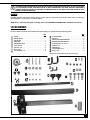
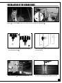
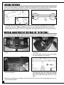
Universal design that adapts to similar
sized tables from most other brands.
Requires two mounting holes in the table
(front & back) for an easy installation.
Complete bandsaw fence system
includes fence, rails and 3 1/2” resaw
guide.
LENGTH
21” FENCE, 29” FRONT RAIL &
25 3/4” REAR RAIL (90-075A)
FITS GENERAL INTERNATIONAL MODEL:
90-100, 90-125, 90-140, 490-1, 590-1 & 690-1
25” FENCE, 29” FRONT RAIL &
25 3/4” REAR RAIL (90-075B)
FITS GENERAL INTERNATIONAL MODEL:
90-240, 90-270, 90-320, 90-360, 90-170/90-170B
& 90-290
28” FENCE & 34” RAILS (90-075C)
FITS GENERAL INTERNATIONAL MODEL:
90-280, 90-460, 90-600 & 90-380
VERSION 2_REVISION 2 - October 12/10
© COPYRIGHT GENERAL INTERNATIONAL 10/2010
GENERAL® INTERNATIONAL
8360 Champ-d’Eau, Montreal (Quebec) Canada H1P 1Y3
Telephone (514) 326-1161 • Fax (514) 326-5555 • www.general.ca
THANK YOU for choosing this Excalibur by General International model 90-075
®
A/B/C Universal Bandsaw Rip Fence System. This Rip Fence System has been carefully tested
and inspected before shipment and if properly used and maintained, will provide you with
years of reliable service. For your safety, as well as to ensure optimum performance and trouble-free operation, and to get the most from your investment, please take the time to read this
manual before assembling, installing and operating the unit.
The manual’s purpose is to familiarize you with the safe operation, basic function, and features
of this Rip Fence System as well as the set-up, maintenance and identification of its parts and
components. This manual is not intended as a substitute for formal woodworking instruction,
nor to offer the user instruction in the craft of woodworking. If you are not sure about the safety of performing a certain operation or procedure, do not proceed until you can confirm, from
knowledgeable and qualified sources, that it is safe to do so.
Once you’ve read through these instructions, keep this manual handy for future reference.
Disclaimer: The information and specifications in this
manual pertain to the unit as it was supplied from the
factory at the time of printing. Because we are committed to making constant improvements, General®
International reserves the right to make changes to
components, parts or features of this unit as deemed
necessary, without prior notice and without obligation to
install any such changes on previously delivered units.
Reasonable care is taken at the factory to ensure that
the specifications and information in this manual corresponds with that of the unit with which it was supplied.
However, special orders and “after factory” modifications may render some or all information in this manual
inapplicable to your machine. Further, as several generations of this model of rip fence system and several versions of this manual may be in circulation, if you own an
earlier or later version of this unit, this manual may not
depict your tool exactly. If you have any doubts or questions contact your retailer or our support line with the
model number of your unit for clarification.
GENERAL® & GENERAL® INTERNATIONAL WARRANTY
All component parts of General®, General® International and Excalibur by General
International ® products are carefully inspected during all stages of production and each unit
is thoroughly inspected upon completion of assembly.
Limited Lifetime Warranty
Because of our commitment to quality and customer satisfaction, General® and General®
International agree to repair or replace any part or component which upon examination,
proves to be defective in either workmanship or material to the original purchaser for the life
of the tool. However, the Limited Lifetime Warranty does not cover any product used for professional or commercial production purposes nor for industrial or educational applications. Such
cases are covered by our Standard 2-year Limited Warranty only. The Limited Lifetime Warranty
is also subject to the “Conditions and Exceptions” as listed below.
Standard 2-Year Limited Warranty
All products not covered by our lifetime warranty including products used in commercial,
industrial and educational applications are warranted for a period of 2 years (24 months) from
the date of purchase. General® and General® International agree to repair or replace any
part or component which upon examination, proves to be defective in either workmanship or
material to the original purchaser during this 2-year warranty period, subject to the “conditions
and exceptions” as listed below.
To file a Claim
To file a claim under our Standard 2-year Limited Warranty or under our Limited Lifetime
Warranty, all defective parts, components or machinery must be returned freight or postage
prepaid to General® International, or to a nearby distributor, repair center or other location
designated by General® International. For further details call our service department at 1-888949-1161 or your local distributor for assistance when filing your claim.
Along with the return of the product being claimed for warranty, a copy of the original proof
of purchase and a “letter of claim” must be included (a warranty claim form can also be used
and can be obtained, upon request, from General® International or an authorized distributor)
clearly stating the model and serial number of the unit (if applicable) and including an explanation of the complaint or presumed defect in material or workmanship.
CONDITIONS AND EXCEPTIONS:
This coverage is extended to the original purchaser only. Prior warranty registration is not
required but documented proof of purchase i.e. a copy of original sales invoice or receipt
showing the date and location of the purchase as well as the purchase price paid, must be
provided at the time of claim.
Warranty does not include failures, breakage or defects deemed after inspection by General®
or General® International to have been directly or indirectly caused by or resulting from;
improper use, or lack of or improper maintenance, misuse or abuse, negligence, accidents,
damage in handling or transport, or normal wear and tear of any generally considered consumable parts or components.
Repairs made without the written consent of General® Internationallwill void all warranty.
TABLE OF CONTENTS
Rules for safe operation . . . . . . . . . . . . . . . . . . . . . . . . . . . . . . . . . . . . . . . . . . . . . . . . . . . . . . . . . . . . . .5
Identification of main parts and components . . . . . . . . . . . . . . . . . . . . . . . . . . . . . . . . . . . . . . . . . . . . . .6
Unpacking & set up . . . . . . . . . . . . . . . . . . . . . . . . . . . . . . . . . . . . . . . . . . . . . . . . . . . . . . . . . . . . . . . . . .6
Assembly tools provided . . . . . . . . . . . . . . . . . . . . . . . . . . . . . . . . . . . . . . . . . . . . . . . . . . . . . . . . . . . . . . . . . . . . . . . . . . . . . . . . .6
Additionnal tools needed . . . . . . . . . . . . . . . . . . . . . . . . . . . . . . . . . . . . . . . . . . . . . . . . . . . . . . . . . . . . . . . . . . . . . . . . . . . . . . . .6
Unpacking . . . . . . . . . . . . . . . . . . . . . . . . . . . . . . . . . . . . . . . . . . . . . . . . . . . . . . . . . . . . . . . . . . . . . . . . . . . . . . . . . . . . . . . . . . . . .7
Installation of the front and rear mounting brackets to the bandsaw’s table . . . . . . . . . . . . . . . . . .8
Installation of the front and rear rails . . . . . . . . . . . . . . . . . . . . . . . . . . . . . . . . . . . . . . . . . . . . . . . . . . .8
Installation of the fence . . . . . . . . . . . . . . . . . . . . . . . . . . . . . . . . . . . . . . . . . . . . . . . . . . . . . . . . . . . . . . .9
Installation of the measuring tape & pointer . . . . . . . . . . . . . . . . . . . . . . . . . . . . . . . . . . . . . . . . . . . .10
Installation of the resaw guide . . . . . . . . . . . . . . . . . . . . . . . . . . . . . . . . . . . . . . . . . . . . . . . . . . . . . . . .11
Leveling the fence . . . . . . . . . . . . . . . . . . . . . . . . . . . . . . . . . . . . . . . . . . . . . . . . . . . . . . . . . . . . . . . . . .12
Vertical adjustment of the fence 90° to the table . . . . . . . . . . . . . . . . . . . . . . . . . . . . . . . . . . . . . . . .12
Alignment of the fence parallel to the miter slot . . . . . . . . . . . . . . . . . . . . . . . . . . . . . . . . . . . . . . . . .13
Parts list & diagrams . . . . . . . . . . . . . . . . . . . . . . . . . . . . . . . . . . . . . . . . . . . . . . . . . . . . . . . . . . . . .14-15
Rules for Safe Operation
To help ensure safe operation, please take a moment to learn the machine’s applications and limitations, as well as potential hazards. General® International disclaims any real or implied warranty and
hold itself harmless for any injury that may result from the improper use of its equipment.
1.
Do not operate the bandsaw when tired, distracted, or under the effects of drugs, alcohol or any
medication that impairs reflexes or alertness.
2.
The working area should be well lit, clean and free
of debris.
15. Use suitable work piece support if the work piece
does not have a flat surface.
16. Hold material firmly against the table.
3.
Keep children and visitors at a safe distance when
the bandsaw is in operation; do not permit them to
operate the bandsaw.
4.
Childproof and tamper proof your shop and all
machinery with locks, master electrical switches
and switch keys, to prevent unauthorized or unsupervised use.
5.
Stay alert! Give your work your undivided attention.
Even a momentary distraction can lead to serious
injury.
6.
Fine particulate dust is a carcinogen that can be
hazardous to health. Work in a well ventilated area
and use a dust collector whenever possible. Wear
protective hair covering to contain long hair and
wear non-slip footwear, approved safety glasses,
dust mask and hearing protection.
7.
Do not wear loose clothing, gloves, bracelets, neck
laces or other jewelry while the bandsaw is in operation.
8.
Be sure that adjusting wrenches, tools, drinks and
other clutter are removed from the machine and/or
the table surface before operating.
9.
Keep hands well away from blades and all moving
parts. Use a brush, not hands, to clear away chips
and dust.
10. Adjust and position upper and lower blade guides
before starting to cut. Upper blade guide should be
adjusted to approximately 1/8” above the material
to be cut.
11. Adjust blade tension and tracking before starting to
cut.
12. Saw teeth must point down toward the table.
13. Be sure that the blade has gained full operating
speed before starting to cut.
14. Always use a clean, properly sharpened blade.
Dirty or dull blades are unsafe and can lead to
accidents.
17. Do not work on long stock without adequate support on the out feed end of the table.
18. If using a power feeder, stop the feeder before stopping the bandsaw.
19. Do not push or force stock into the blade. The bandsaw will perform better and more safely when working at the rate for which it was designed.
20. Avoid working from awkward or off balance positions. Do not overreach and keep both feet on floor.
21. Keep guards in place and in working order. If a
guard must be removed for maintenance or
cleaning, be sure it is properly re-attached before
using the tool again.
22. Never leave the machine unattended while it is running or with the power on.
23. Use of parts and accessories NOT recommended
by General® International may result in equipment malfunction or risk of injury.
24. Never stand on machinery. Serious injury could
result if the tool is tipped over or if the cutting tool is
unintentionally contacted.
25. Always disconnect the tool from the power source
before changing accessories such as blades, or
before performing any maintenance or cleaning,
or if the machine will be left unattended.
26. Make sure that the switch is in the “OFF” position
before plugging in the power cord.
27. Make sure the tool is properly grounded. If
equipped with a 3-prong plug it should be used
with a three-pole receptacle. Never remove the
third prong.
28. Do not use this bandsaw rip fence for other than its
intended use. If used for other purposes, General®
International disclaims any real implied warranty
and holds itself harmless for any injury, which may
result from that use.
5
UNIVERSAL BANDSAW RIP FENCE SYSTEM
90-075A/B/C
IDENTIFICATION OF MAIN PARTS AND COMPONENTS
FENCE
FENCE LOCKING HANDLE
FRONT FENCE RAIL
POINTER
REAR FENCE RAIL
SCREW (ECCENTRIC SHAFT)
RESAW GUIDE
FENCE ALIGNMENT BOLTS
FENCE BASE
UNPACKING & SET UP
6
ASSEMBLY TOOLS PROVIDED
ADDITIONAL TOOLS NEEDED
• (1) 10/12 mm Combination Wrench
• (1) 5 mm Allen key
• (1) 3 mm Allen Key
•
•
•
•
•
Flat head screwdriver
8 mm Allen key
Machinist square
Measuring tape or ruler
Feeler gauge (optional)
TO REDUCE THE RISK OF DAMAGE TO THE BANDSAW, THE FENCE SYSTEM OR THE WORK PIECE, AS WELL AS THE POTENTIAL FOR PERSONAL INJURY, AFTER INITIAL SET-UP AS WELL AS BEFORE EACH USE, MAKE SURE THAT EVERYTHING IS
SECURELY INSTALLED AND THAT ALL FASTENERS AND MOVING PARTS ON THIS FENCE SYSTEM ARE LOCKED IN PLACE
BEFORE STARTING THE BANDSAW.
UNPACKING
Carefully unpack and remove the Rip Fence System and its components from the box and check for missing or
damaged items as per the list of contents below.
NOTE: Please report any damaged or missing items to your GENERAL® INTERNATIONAL distributor immediately.
LIST OF CONTENTS
Once the parts have been removed from the packaging, you should have the following items:
Qty
FENCE. . . . . . . . . . . . . . . . . . . . . . . . . . . . . . . . . . . . . 1
RESAW GUIDE . . . . . . . . . . . . . . . . . . . . . . . . . . . . . . 1
FRONT RAIL . . . . . . . . . . . . . . . . . . . . . . . . . . . . . . . . 1
REAR RAIL. . . . . . . . . . . . . . . . . . . . . . . . . . . . . . . . . . 1
MEASURING TAPE . . . . . . . . . . . . . . . . . . . . . . . . . . . 1
LOCK KNOB. . . . . . . . . . . . . . . . . . . . . . . . . . . . . . . . 2
HEX NUT 1/4” . . . . . . . . . . . . . . . . . . . . . . . . . . . . . . . 2
BOLT (M6) . . . . . . . . . . . . . . . . . . . . . . . . . . . . . . . . . 4
FLAT WASHER 1/4” . . . . . . . . . . . . . . . . . . . . . . . . . . . 8
Qty
LOCK WASHER . . . . . . . . . . . . . . . . . . . . . . . . . . . . . . 4
HEX NUT . . . . . . . . . . . . . . . . . . . . . . . . . . . . . . . . . . 4
FRONT MOUNTING BRACKET . . . . . . . . . . . . . . . . . . 2
REAR MOUNTING BRACKET . . . . . . . . . . . . . . . . . . . 2
LOCK KNOB 5/16” X 5/8”. . . . . . . . . . . . . . . . . . . . . 2
SCREW 5/16” . . . . . . . . . . . . . . . . . . . . . . . . . . . . . . . 2
SQUARE NUT . . . . . . . . . . . . . . . . . . . . . . . . . . . . . . . 4
FLAT WASHER 5/16” . . . . . . . . . . . . . . . . . . . . . . . . . . 2
* R BOLT 1/4” . . . . . . . . . . . . . . . . . . . . . . . . . . . . . . . . 4
*Models 90-170/90-170B, 90-290 and 90-380 only.
*
7
INSTALLATION OF THE FRONT AND REAR MOUNTING BRACKETS
TO THE BANDSAW’S TABLE
Note: The M6 bolts, washers, lock washers and hex nuts required for this step are provided with your Excalibur® Universal
Bandsaw Rip Fence System. However, if they do not fit into the mounting holes on your table, use the fasteners provided
with your original fence.
ORDER OF
ASSEMBLY
a. Bolt
b. Washer
c. Mounting
bracket
d. Table
e. Washer
f. Lock washer
g. Hex nut
1. The image above shows the positioning of the
mounting brackets when properly installed to the
table (front and rear brackets are installed at opposite sides of the table).
2. Place the bolts, washers, lock washers and hex nuts
as shown above to attach the mounting brackets
(front and rear) to the table. Don’t tighten the nuts
yet.
INSTALLATION OF THE FRONT AND REAR RAILS
Note: The front rail is the wider one of the two rails.
8
1. Install a 5/16" screw
, a flat washer
, and a
square nut
on both front mounting brackets.
2. Install a 5/16" x 5/8" lock knob
and a square nut
on both rear mounting brackets.
3.
4. Then, slide the rail onto the second square nut
Insert the square nut
of the first front mounting
bracket into the T-slot of the front rail
.
.
5. Insert the square nut
of the first rear mounting
bracket into the T-slot of the rear rail .
6. Then, slide the rail up to the second square nut
.
7. Position the rails
to the left or right of the table ,
depending upon the size of your bandsaw
i.e.
the space between the frame of the saw and the
blade (see image left), and your personal preferences, then tighten the nuts to lock the rails in position.
Tip: You can adjust the rail positioning in relation to the
blade as needed to accommodate the need for more cutting capacity. For example, if you intend to use this fence for
cutting longer or wider workpieces, it may be preferable to
position the fence rails further to the right. For shorter workpieces (that fit between the frame of the saw and the
blade), position the rails further to the left.
Note: You can always reposition the fence rails further left or right as needed. However, once the measuring tape is installed
(see “Installation of the measuring tape and pointer” on page 8) on the front rail, you’ll be able to use the zero reference of
the tape only when the rail is positioned as it was during initial alignment. When the rails are repositioned, you will need to
use a separate measuring tape (or ruler) to determine the distance between the fence and the blade. You will still be able to
use the tape as a reference, but not for accurate measurements from the zero point.
INSTALLATION OF THE FENCE
lock mechanism
lock
unlock
1. Position the fence
rail .
firmly down on top of the front
2. Make sure the bearings
are sitting flush on the
rail, then lock down the fence locking handle
.
9
INSTALLATION OF THE MEASURING TAPE AND POINTER
1. Place the fence
to the right of the saw blade, so it
touches the blade , then lock down the fence .
2. With a 3 mm Allen key, unscrew and remove the
screw
that holds the pointer
into the right
pointer’s window
of the fence base.
3. Make a pencil mark on the rail, in line with the pointer’s center mark. Then, unlock the fence and put
aside the pointer, screw and fence for now.
4. Cut the measuring tape between both zeros
.
Remove the backing strip from the first half of the
measuring tape (the one with the zero on the left)
and carefully install along the rail slot, using your
pencil mark as the zero-point of the tape . Trim off
excess tape wih a knife or scissors.
Tip:
Try removing only an inch of backing strip from the start of the tape, stick that down, then remove the rest of the backing and pull the measuring tape taut to the end of the rail slot and carefully lower it against the slot.
Note: For accurate readings, the tape must be placed straight parallel with the rail slot, with no folds along its length.
5. Reinstall the fence on the front rail and lock it
down. Then, reinstall the pointer (place the screw in
the middle of the hole to allow maximum adjustment capacity on the left or right afterward), and
slide the pointer right or left, so that its center mark
is in line with the zero-point
of the tape.
Tighten the screw to lock the pointer in place.
6. Unlock the guide fence and repeat steps 1 to 5 with
the fence to the left of the blade this time, aligning
the center mark of the left pointer with the zero of
the second half of the measuring tape.
Note:
Recheck and, if necessary, readjust the left and right pointers against the zero-point of both measuring tapes whenever you change blades. Different blades have different thicknesses, which can throw off the pointer a few fractions.
10
INSTALLATION OF THE RESAW GUIDE
The 3 1/2" resaw guide
facilitates resawing of wide boards by allowing you to pivot your workpiece on its curved
surface
to correct the line of the cut as you push the work piece into the blade .
1. Screw a hex nut onto each of the 2 lock knobs ,
just a few turns only, leaving a good space between
the nut and the knob .
2. Slide the nut/knob sets into the slots on the flat face
of the resaw guide with the nuts on the outside face
as shown above.
3. Slide the resaw guide onto the fence by sliding the
nuts into the slot
in the fence, from the rear.
4. Position the resaw guide along the fence, lining up
the center of the guide with the blade of the saw.
11
LEVELING THE FENCE
The fence should be parallel to the bandsaw’s table and sit approximately 2 mm above the table’s surface (so the
fence will not scratch the table and a thin work piece will not get stuck or jammed under the fence.)
2 mm
2 mm
1. To level and adjust the height of the fence, loosen the hex nuts that hold the mounting brackets to the table
(see image left), and raise
or lower
the front and rear rails along the elongated holes in the mounting
brackets. Level the fence, front and back as needed, and set the spacing between the bottom of the fence
and the table to 2mm (approx.) as shown in image right. Then, tighten the hex nuts to lock the rails in position.
VERTICAL ADJUSTMENT OF THE FENCE 90° TO THE TABLE
Place a machinist square on the table against the fence (See Step 4 below) and, either by eye or with a feeler gauge,
look for a gap between the square and the fence (bottom and top) or the table. If needed, adjust as follows.
1. Remove the fence from the rails and turn it up side
down.
2. With a 5 mm Allen key, loosen the set screw (without
removing it).
3. Put the fence back on the rails, but do not engage
the locking handle to lock the fence.
4. Reposition the square on the table against the
fence as a reference.
5. With a flat head screwdriver, slowly turn the screw
(eccentric shaft) on the fence base. This will tilt the
fence slightly, allowing you to eliminate the gap
between the square and either the fence or the
table.
6. With the fence adjusted 90° to the table, remove it from the rails, turn it up side down and retighten the set screw
to lock the fence in place.
12
ALIGNMENT OF THE FENCE PARALLEL TO THE MITER SLOT
To make satisfactory rip cuts, your fence must be aligned perfectly parallel with the miter slot in the table. Slide the
fence over to the T-slot on your saw, as shown in the second diagram. Lock down the fence handle and make a visual check to verify if the fence is parallel with the T-slot along its entire length. You can also place a small block of
wood, upright into the T-slot and slide it from front to back checking its distance from the face of the fence.
If the fence is not parallel, it can be adjusted as follows:
1. Make sure the guide fence is locked on the rails
(locking handle down).
3. Manually adjust the fence
the miter slot
.
, so that it is parallel with
2. With a 8 mm Allen key, loosen (without removing)
both screws
that attach the fence to the fence
base.
4. Hold the fence in place with one hand and tighten the
first screw
.
5. If needed, adjust a little further with the remaining bit of
play, then tighten the second screw .
13
F29
F30
F31
F01
F02
F29
F03
F21
F36
F20
F04
F03
F35
F19
F05
F06
F34
F07
F08
F06
F07
F09
F10
F11
F23
F22
F26
F24
F25
F13
F12
F14
F13
F14a*
F17
F14
F28
F27
F16
F17
F14a*
F33
F32
F15
F27
F18
F27
*Models 90-170/90-170B, 90-290 and 90-380 only.
14
F32
F27
PARTS LIST
90-075A/B/C
PART N0.
DESCRIPTION
SPECIFICATION
90075-F01A
90075-F01B
90075-F01C
90075-F02
90075-F03
90075-F04
90075-F05
90075-F06
90075-F07
90075-F08
90075-F09
90075-F10
90075-F11
90075-F12A
90075-F12B
90075-F12C
90075-F13
90075-F14
90075-F14a*
90075-F15
90075-F16
90075-F17
90075-F18
90075-F19
90075-F20
90075-F21
90075-F22
90075-F23
90075-F24
90075-F25
90075-F26A
90075-F26B
90075-F26C
90075-F27
90075-F28
90075-F29
90075-F30
90075-F31
90075-F32
90075-F33
90075-F34
90075-F35
90075-F36
FENCE BODY 21” (FOR 90-075A)
FENCE BODY 25” (FOR 90-075B)
FENCE BODY 28” (FOR 90-075C)
SOCKET HEAD SCREW
10X25
SOCKET HEAD SCREW
5X10
FENCE BASE
SET SCREW
1/4X1/4
C-RING
S10
BEARING
6200
ECCENTRIC SHAFT
PRESSURE PLATE
PIN
6X43
SCALE
FRONT FENCE RAIL 29” (FOR 90-075A)
FRONT FENCE RAIL 29” (FOR 90-075B)
FRONT FENCE RAIL 34” (FOR 90-075C)
SQUARE NUT
BOLT
(M6)
R BOLT
1/4”
BRACKET (FRONT)
LOCK KNOB
5/16”X5/8”
HEX NUT
M6
SCREW
5/16”
POINTER
CAP SCREW
6X10
FOOT
BEARING SHAFT
LOCK MECHANISM
NUT
8MM
FENCE HANDLE
REAR FENCE RAIL 25 3/4” (FOR 90-075A)
REAR FENCE RAIL 25 3/4” (FOR 90-075B)
REAR FENCE RAIL 34” (FOR 90-075C)
FLAT WASHER
1/4”
L BRACKET (REAR )
HEX NUT
1/4”
RESAW ATTACHMENT
LOCK KNOB
LOCK WASHER
1/4”
FLAT WASHER
5/16”
OPEN END WRENCH
10/12MM
ALLEN KEY
5MM
ALLEN KEY
3MM
QTY
1
1
1
2
2
1
2
2
2
1
1
1
1
1
1
1
4
4
4
2
2
4
2
2
1
1
1
1
1
1
1
1
1
8
2
2
1
2
4
2
1
1
1
*Models 90-170/90-170B, 90-290 and 90-380 only.
15
MODEL 90-075/A/B/C
8360 Champ-d’Eau, Montreal (Quebec) Canada H1P 1Y3
Fax: (514) 326-5565 -
Tel.: (514) 326-1161
Fax: (514) 326-5555 -
Parts & Service /
Order Desk
[email protected]
www.general.ca
IMPORTANT
When ordering replacement parts, always give the model number, serial number of the machine and
part number. Also a brief description of each item and quantity desired.