1
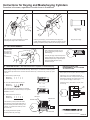
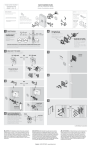
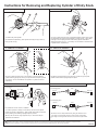
Instructions for Removing and Replacing Cylinder of Entry Knob.
A. ALIGN SPINDLE
B. REMOVE SPINDLE
4
2
1
2
6
3
5
3. Insert cylinder removing tool (2) edgewise between screw stem (5) and
1. Remove key from Cylinder.
boss (3) with slot (4).
the detent slide (6) rotating tool clockwise to position shown. Apply slight
leverage to remove spring tension while holding spindle downwards
allowing spindle to drop out. If necessary use free thumb to assist removal.
If spindle rotates, repeat step 2.
C. REMOVE CYLINDER
D. REPLACE SPINDLE
2. Rotate Round Spindle (1) with cylinder removing tool (2) to line up
4
3
7
4. Insert cylinder removing tool in lock housing (7) pushing together
5. Replace round spindle by lining up boss (3) with slot (4) and push
E. REPLACE CYLINDER
F. HOW TO DETERMINE HAND OF DOOR
cylinder retaining springs by moving tool up and down and push cylinder
out of knob. If door not available, note position of cylinder in knob for
reassembly.
PIN COVER UP
KEY CUTS UP
spindle until the detent spring snaps into place.
For Inswinging Door
Inside
Left Hand
Right Hand
Outside
RETAINING
SPRING
For Outswinging Door
Left Hand
6. Install knob on door if door is available.
Inside
Right Hand
Outside
7. Position cylinder so that pin cover and key cuts are in the upward
position (as shown in illustration). Align cylinder with guides in knob and
insert, pressing until retaining springs snap into position.
8. If key will not remove, begin again at step “A” and insure step ”E”
procedures are followed.
The hand of a door is always determined by facing the outside of a door.
If the hinge is on the left side of the door, then the door is left-handed.
If the hinge is on the right side of the door, then the door is right-handed.
WARNING: This Manufacturer advises that no lock can provide complete security by itself. This lock may be defeated by forcible or technical means, or evaded by entry
elsewhere on the property. No lock can substitute for caution, awareness of your environment, and common sense. Builder’s hardware is available in multiple performance
grades to suit the application. In order to enhance security and reduce risk, you should consult a qualified locksmith or other security professional.
01058-06
Instructions for Keying and Masterkeying Cylinders
Procedure is the same, regardless of model shown in illustrations.
A. REMOVE PLUG CLIP
B. REMOVE PLUG
C. REMOVE OLD PINS
2
1
Push plug clip (1) off with screwdriver or cylinder
removing tool, using a side to side motion.
Insert key and turn plug 1/4 turn clockwise. Push plug out of
cylinder with plug following tool (2) and leave in cylinder. The plug
following tool will keep the top tumbler pins and springs in place.
D. KEY MEASUREMENT
E. FOR RANDOM KEYING
Measure cuts of
key or keys as
illustrated, and
write down key
cut
combinations.
Note: Random keying uses only one
key. For multiple keys, skip to step F
(Masterkeying).
1 0
3 2
5 4
6
7
Insert key into plug. Drop bottom pins into
proper holes with pin numbers that match
measured depths. Tops of pins should be
flush with outside diameter of plug.
Proceed to step G.
F. MASTER KEYING
Kits 236 and 272 are capable of masterkeying.
Master keying is making one lock work with two keys. Take two keys – one will be the master key which
will be able to open all the locks. The other will be the random key or the tenant‘s key, which only opens
one lock.
1. Read both keys, (see step D)
Master Key
Random Key
Drop pins out of plug.
5
4
4
4
3
1
2
6
2. Circle the smallest number of each cut.
5
4
3
2
2
Random Key
4
4
1
6
4
REASSEMBLY OF CYLINDER
AFTER KEYING
After proper pins are in place, leave key in plug.
Hold plug in 1/4 turn clockwise position, as
when it was removed, in step B. Push the plug
against plug following tool until the tool is fully
out of cylinder and plug is all the way in.
2
4
Master Key
G. INSTRUCTIONS FOR
Install plug clip (1) downward as shown, then
remove key.
4 4 1 2 2
1
1 0 2 4 2
The circled numbers are your bottom pins required.
Drop in the bottom pins without the key in the cylinder.
EXAMPLE - 44122
3. Take the difference of each cut.
Master Key
Random Key
5
4
1
4
4
0
3
1
2
2
6
4
2
4
2
TOP PINS
MASTER PINS
SHEAR LINE
The difference (10242) will be the master
pins required. Drop in these master pins on
top of the bottom pins without the key in the
cylinder. A 0 means that a master pin is not
put in that hole.
4. Put plug back into the cylinder
assembly without key in the plug.
BOTTOM PINS
Lake Forest, California U.S.A.
Copyright © 2010 Black & Decker Corporation
01058-06