1
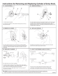
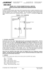
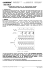
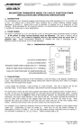
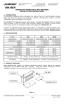
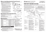
Securitron Magnalock Corp. Tel 800.624.5625 www.securitron.com [email protected] ASSA ABLOY, the global leader in door opening solutions SECURITRON MODEL MSS-1 MAXIMUM SECURITY SWITCH INSTALLATION & OPERATING INSTRUCTIONS 1. DESCRIPTION Securitron’s maximum security magnetic switch is intended to monitor the open or closed position of doors, windows, machinery safety barriers or other movable assemblies in critical environments where an attempt to defeat the switch is a concern. The switch includes numerous design features that make it highly defeat resistant, reduce false alarms and provide for easy and accurate installation. It is available in two versions to deal with different physical mounting conditions and may be used indoors or outdoors. Each version consists of two pieces: the switch module and the magnet pack. The MSS-1 is mainly intended for use on doors and includes a jacketed cable which can be hidden in the door frame. The MSS-1G provides a stainless steel jacketed cable which is suitable for a range of applications where the cable cannot be hidden and must resist possible attack. 2. DEFEAT RESISTANCE ISSUES The most common approach used to defeat a magnetic switch is to introduce an external magnet near the switch module so that the door, window or other barrier can be opened without the switch alarming. The MSS cannot be defeated in this way as its own magnet pack (which contains a magnet array) must be used to put it into the secure state. If a very powerful external magnet is used in an attempt to defeat the MSS, it may even put the MSS into alarm. Another method which represents a more serious threat is when an intruder attempts to defeat the switch by obtaining a second MSS magnet pack. If access to the MSS can be obtained, the switch might be defeated by positioning the second magnet pack near the switch module in a manner that permits the door to be opened without an alarm being signaled. The MSS design includes two defenses against this risk. The first is called co-planar operation. The switch will only respond to the magnet pack if the pack is located in roughly the same plane as the switch. A second magnet pack placed in proximity to the switch will not activate the switch because it will be off-plane. In effect, there is only room for one magnet pack being read by the switch at a time, so a second pack cannot compromise security. CO-PLANAR OPERATION SWITCH MAGNET PACK TO ENHANCE DEFEAT RESISTANCE, THE MAGNET PACK CAN ONLY BE In certain physical situations however it may be READ IN A NARROW ANGLE possible to slowly open the door and slowly introduce a IN FRONT OF THE SWITCH. second magnet pack. The MSS includes an extra defense against this. The product is manufactured in different types. The magnet pack must be of the same type as the switch module to work. The MSS is delivered as a matched pair with no marking that identifies its type. Therefore, a person attempting the difficult task of trying to slowly open a barrier while introducing a second MSS magnet pack in an attempt to defeat the switch may well have the wrong type pack. Another attack possibility is removal of the switch module. This can serve several purposes. It can provide access to the cable (assuming the cable is hidden in the door frame). It can also be part of an attempt to remove both the switch module and the magnet pack as a unit to permit opening the door or window without triggering an alarm. To forestall this, the MSS includes a hidden tamper switch feature. The tamper switch provides a two wire output which is normally closed and opens if the switch is removed. This line can be separately monitored or connected in series with the main switch output. See Section 3. Finally, a very serious threat is removal of the magnet pack from the door. If the magnet pack can be removed from the door and maintained at a correct distance from the switch module, clearly the door can be opened without signaling an alarm. The MSS’s mounting methods coupled with co-planar operation, however, preclude this. See Sections 3.2 and 3.3. To conclude, in a security application, the MSS’s array of anti-defeat features will almost always result in the alarm sounding while the switch is being tampered with. This can lead to the person attempting to defeat the switch being identified and detained. © Copyright, 2011, all rights reserved Page 1 PN# 500-16700 Rev. D, 03/13 3. PHYSICAL INSTALLATION The MSS can be used to monitor the opening of doors, windows, gates and barriers of all types. The switch module is mounted on the part of the assembly that is fixed (such as a door frame) and the magnet pack is mounted on the part of the assembly that moves (the door, for example). Unlike many magnetic switches, the performance of the MSS is unaffected by the type of surface it’s mounted on. It will perform the same on steel as on wood. In planning for mounting the MSS, note that the switch and the magnet pack have to be oriented correctly, have to be roughly in the same plane and have to be a defined distance apart. To obtain correct orientation, note the arrows on the labels on each component. The arrows have to directly face each other and the ends of the two pieces must be even, not offset. SEPARATION DISTANCE THE ARROWS ON THE SWITCH AND MAGNET PACK MUST FACE EACH OTHER AND AND THE ENDS OF EACH COMPONENT MUST BE EVEN- NOT OFFSET. The MSS includes a minimum and maximum operating distance. The unit will report secure only when the separation distance is between this maximum and minimum. If the magnet pack is too close to the switch module or too far away, the unit will alarm. SEPARATION DISTANCE IS SPECIFICALLY NOTED FOR EACH INDIVIDUAL PAIR. The distance between the minimum and maximum separation points is called the gap. The MSS provides a gap of 4/10”-1/2” (10-12.5MM). For best reliability, you want to set the actual separation distance exactly midway in the gap. The gap will, however, vary somewhat on each unit and the minimum distance at which the gap starts will also vary. You can, of course determine the optimum midway separation distance by using a ruler and Ohmmeter but as part of our QC procedure, we have checked this distance and it is printed on the switch module label. Use this separation distance when you mount the unit. The tamper feature on the MSS works as follows. An oval head screw (supplied) is set into the surface which is to receive the switch module. Two metal washers are placed under the screw head to yield the correct height. The template shows positioning of this screw. When the switch module is installed, the tamper screw depresses the tamper switch. This closes the two wire tamper circuit. Note that if you push the tamper switch in with a paper clip for example, you’ll hear it click. This is not the switching point. Switching occurs much earlier in the travel so that the height of the screw head will always move the tamper switch past its switch point but will not bottom it out which could damage the tamper switch. Make sure, however that you place the two metal washers under the tamper screw head and then screw it down flush with the mounting surface. This sets up the correct height of the screw head. Note also the fact that the switch module is tampered is undetectable and any attempt to remove the switch module will open the tamper circuit. This circuit may be directly monitored (usually by a 24 hour circuit) or connected in series with the closed loop of the main switch output such that a tamper violation will create the same alarm signal as if the door was opened. 3.1 CABLE PROTECTION The Underwriter’s Laboratories standard for high security switches requires that a cable sheathed in plastic such as the MSS-1 cable must be protected from attack by being routed through a metal frame. This is most commonly a door frame but could also be the frame of a gate or other opening. The mounting methods described in sections 3.2, 3.3 and 3.4 show in detail how this is to be accomplished. If your application is such that the cable cannot be routed through a metal frame member and therefore fully protected, you must use model MSS-1G which includes a stainless steel protective jacket for the cable (see section 3.5). This alternative will satisfy UL’s requirements. Page 2 PN# 500-16700 Rev. D, 03/13 3.2 OUTSWINGING DOOR INSTALLATION The MSS-1 version with long jacketed cable is intended for a protected and unobtrusive installation on outswinging doors. The drawing to the right shows the preferred configuration. HEADER Start by mounting the magnet pack on the door. Note that the magnet pack has two sets of screw holes. Select the magnet pack position so that the arrow on its label is pointing towards the switch module. As the drawing shows, the label is on the top of the pack (facing up). Then mount the magnet pack as shown. Drill 7/64” (2.75MM) diameter pilot holes for the #8 mounting screws. Don’t drop it below the door stop by more than 1/8” (3MM) as it must remain roughly in the same plane as the switch. CABLE LABEL TAMPER SCREW STOP DOOR SEPARATION DISTANCE MAGNET PACK SWITCH MODULE Next, mount the switch. Set the leading edge of the switch to match the separation distance printed on the label. Make sure the switch label arrow points at the magnet pack arrow and, using the template, drill 7/64” (2.75MM) diameter holes for the #8 mounting screws and a 3/8” (9.5MM) diameter hole for the cable which will be concealed in the door frame. If you are planning to use the tamper feature of the switch, drill a 3/32” (2.25 MM) diameter hole for the #6 tamper screw, again following the template. Be sure to use the two metal washers on the tamper screw to yield the correct height. This installation technique produces an attractive and high security result. Note that with this mounting method, the magnet pack cannot be removed without opening the door which would result in an alarm event. Some outswinging doors pose special problems. Many aluminum frame glass doors have what is called a blade stop. This is typically about 1/8” (3MM) in width and obviously cannot accept the switch. There are two solutions for this situation. The most professional is to cut out a section of the blade stop just large enough to mount the magnet pack on the door. The switch than mounts directly on to the header which also conceals the cable. An alternate method is to employ a spacer block to position the switch down far enough to clear the blade stop. The magnet pack can then mount lower on the door. This method requires pulling the cable through the spacer block up into the header and also has the disadvantage of weakening the security of the tamper switch. The tamper switch will trigger if the switch module is removed from the spacer block but not if the spacer block is removed from the header while being held tight against the switch module. Another door problem can occur if a conventional stop is not as wide as is necessary to mount the switch (considering the set-back needed for the magnet pack and separation distance). The back part of the switch will be hanging in space. A spacer piece can be added to the stop to widen it, but note that the switch module can be successfully mounted with only its two front screws. The cable exit has been deliberately located forward so that the cable can be concealed successfully in a narrow door stop. The tamper switch, however, may be unusable. TAMPER SCREW HEADER LABEL Start by mounting the magnet pack on the door. Note DOOR that the magnet pack has two sets of screw holes. Select the magnet pack position so that the arrow on its label is pointing towards the switch module. As the drawing shows, the label is facing towards the door. The magnet pack should then be mounted as shown. Drill 7/64” (2.75MM) diameter pilot holes for the #8 mounting screws. Page 3 SWITCH CABLE STOP 3.3 INSWINGING DOOR INSTALLATION The MSS is generally mounted on the inswinging side of a door when that side represents the protected area. The drawing to the right displays a cross section of this configuration. It shows the unit mounted at the top of the door but naturally the unit can also be mounted on the side. SEPARATION DISTANCE MAGNET PACK PN# 500-16700 Rev. D, 03/13 Next, mount the switch module. Set the leading edge of the switch to match the separation distance printed on the label. Make sure the switch label arrow points at the magnet pack arrow and, using the template, drill 7/64” (2.75MM) diameter holes for the #8 mounting screws and a 3/8” (9.5MM) diameter hole for the cable which will be concealed in the door frame. If you are planning to use the tamper feature of the switch, drill a 3/32” (2.25MM) diameter hole for the #6 tamper screw, again following the template. Be sure to use the two metal washers on the tamper screw to yield the correct height. This installation technique produces an attractive and high security result. A particular benefit of an inswinging door installation is that when the door opens, it sweeps out the area under the switch. Therefore someone trying to defeat the switch with a second magnet pack would be unable to position it in the co-planar position because of movement of the door. Co-planar operation also precludes defeating the switch by removing the magnet pack. As soon as the pack is off-plane an alarm will be signaled. 4. WIRING The MSS has five wires that are assigned by color as follows: White = Common Green = NC Orange = NO Red = Tamper NC Black = Tamper NC GREEN NC Because we’re using the terms normally open and normally ORANGE closed, it’s necessary to define what we mean by “normal”. NO The normal condition of the MSS is when it is reporting WHITE COM secure (the magnet pack is at the separation distance from RED the switch module). So, for example, you’ll read a closed TAMPER NC circuit between White and Orange if you meter the switch BLACK module in alarm condition (magnet is not near the switch TAMPER NC module) but you’ll read open if you meter it in the secure condition. SCHEMATIC SHOWS SWITCH IN SECURE CONDITION WITH TAMPER The Red and Black tamper wires will be closed when the FEATURE IN USE. CONTACTS WILL tamper switch is in secure condition (depressed by the SWITCH WHEN SWITCH ALARMS OR TAMPER IS VIOLATED. tamper screw) and open if the tamper switch is undisturbed (alarm condition). Separate connection of the main switch output and the tamper output requires two alarm points. Generally, the switch output is connected to a point which is subject to arming and disarming depending on the time of day. The tamper contacts are connected to a 24 hour point to raise an alarm any time the switch module is tampered with. If two alarm points are not available (because of wire count limitations for example) the tamper output can be wired in series with the switch’s NC loop. With this connection (shown in the drawing to the right), the circuit will open creating an alarm condition if either the door opens or the switch module is tampered with while the door is closed. GREEN NC SERIES CONNECTION OF SWITCH AND TAMPER NC LOOPS TO MAINTAIN BOTH FEATURES WITH A SINGLE ALARM POINT. WHITE RED BLACK COM Maximum contact ratings depend on the voltage put through the switch. They are 250 mA at 12V or less and 125 mA at 24V. In special applications, the switch can accept up to 100V but the current must be proportionately limited to a maximum 3 watt power rating (60 mA at 50V; 30 mA at 100V). The tamper circuit can handle a maximum of 1 Amp. 5. MAGNACARE LIFETIME REPLACEMENT WARRANTY For warranty information visit www.securitron.com/en/site/securitron/About/MagnaCare-Warranty/ PATENT NOTE: The products discussed in this manual are covered under US patent #5,668,533 Page 4 PN# 500-16700 Rev. D, 03/13