1
PK.2716
*Note: #8 Oval Head Screws are not required on 3” rose styles.
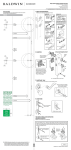
KNOB
ROSE
OUTSIDE
ADAPTOR
LATCH
SET SCREW
INSIDE
ADAPTOR
STRIKE
PLATE
#8 X 3/4” OVAL
HEAD SCREWS
(*See note.)
RETAINER
NYLON WASHER
FACE
PLATE THREADED STUD
(Privacy Version)
PRIVACY
BUTTON EXTENSION
Installation Instructions
Passage, Privacy, Full & Half Dummy
(PRIVACY VERSION)
ALIGNMENT
BUSHING
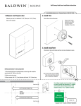
DOOR PREPARATION: PASSAGE & PRIVACY LATCHSETS ONLY
1. Fold the template
on the line and
locate on at desired
height (about 40”
from floor). Place
folded edge on low
side of door bevel.
Mark holes on door
for appropriate
backset, rose style
and size.
TEMPLATE
2. Caution: Recheck
bore hole locations
before drilling. Drill
the 2-1/8” Face Bore
through the door first.
Drill the 1” diameter
Edge Bore through
to the inside of the
2-1/8” Face Bore.
For 5” & 10” rose
styles, mark but do
not drill pilot holes
for #8 surface mount
screws. This will be
done in a later step.
1” DIA.
EDGE
BORE
3. Insert the latch
into the edge of
the door. Trace
an outline of the
faceplate onto the
door edge. Mark
screw hole center
locations and drill
1/8” pilot holes.
5” & 10” roses may
be installed as shown.
ROSE
#8 X 3/4”
COMBINATION
SCREWS
Interior Latchset
1-1/4”
FLAT HEAD
SCREWS
4. Chisel out the
area marked in step
3 to a depth of 5/32”
or until faceplate
is flush with door
edge. Proceed to
Passage or Privacy
installation.
EMERGENCY KEY
(PRIVACY VERSION)
ALLEN
WRENCH
PRIVACY BUTTON
(PRIVACY VERSION)
STRIKE PREPARATION: PASSAGE & PRIVACY LATCHSETS ONLY
1. Using the strike
portion of the
marking template,
locate and mark
strike mounting
screws and
centering points for
your door thickness.
2. Align the strike
and trace outline
onto the door frame
using mounting
screw marks for
location.
3. At the screw
marks, drill (2) 1/8”
dia. pilot holes for
the screws. Bore
7/8” dia. X 3/4”
deep hole.
4. Chisel out the
area marked in
step 2 to a depth of
1/16” or until strike
is flush with door
frame.
Install strike using
(2) #8 Flat Head
combination screws.
7/8”
EDGE BORE
2-1/8”
FACE
BORE
1/8” PILOT HOLES
FOR #8 SCREWS
HALF DUMMY INSTALLATION
BACKPLATE
ROSE
#8 X 3/4” OVAL
HEAD SCREWS
(*See note.)
KNOB
1. Locate the position for hole in door.
If not used with a
double door, the
hole location should
be approx. 40” from
floor. Drill a 5/8”
hole ¼” deep one
side of the door
DO NOT DRILL
THROUGH DOOR.
2. Place backplate on door so that the flat
surface is toward the floor. The flat surface
should be parallel to the floor and perpendicular to the door edge. A builder’s square
should be used for best results. Using the
backplate as a template, mark center locations
for (3) screw holes.
Remove backplate and pre-drill (3) holes for
screws ½” deep using a 1/16” drill bit. Install
backplate with (3) flat head screws provided.
FLAT HEAD
SCREWS
3. Attach the roses
by screwing the
threaded retainer
onto the adaptors.
Orient the rose as
desired and securely
tighten by using the
spanner tool.
For 5” & 10” roses,
ensure rose is parallel with door edge
and drill 3/32” x 1/2“
deep pilot holes at
marked locations.
Install #8 oval head
screws into door.
BACKSET DIMENSION
(2-3/8” OR 2-3/4”)
*Note: #8 Oval Head Screws are not required on 3” rose styles.
DOOR EDGE
SET SCREW
SPANNER TOOL
a
RETAINER
DOOR EDGE
MARK LOCATION
OF 3 SCREW HOLES
4. Orient the
knob or lever so
the set screw is
pointed down
& toward the
hinges of the
door. Slide the
knob or lever
onto the end
of the spindle
until it touches
the adaptor and
secure with set
screw.
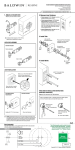
PASSAGE LATCHSET INSTALLATION
2. Install the inside
adaptor. This adaptor
will have thru-holes for
the flat head screws to
fit into.
1. With backset marking
facing up, grasp the
faceplate and rotate to
assure bevel side of
latchbolt faces jamb.
Slide the latch into the
door as shown and
secure with (2) #8-3/4”
combination screws
3. Install the outside
adaptor. Insert the flat
head screws through
the inside adaptor and
into the outside adaptor.
Do not fully tighten at
this time.
4. Insert the spindle
into the latch with the
ends protruding from
both adaptors. Slide
the alignment bushings
onto the spindle ends
and into the adaptors.
Tighten the screws and
remove the alignment
bushings.
5. Remove the spindle.
Attach the roses by
screwing the threaded retainer onto the adaptors.
Orient the rose as desired
and securely tighten by
using the spanner tool.
For 5” & 10” roses,
ensure rose is parallel
with door edge and
drill 3/32” x 1/2“ deep
pilot holes at marked
locations. Install #8 oval
head screws into door.
a
BACKSET MARKING
6. Insert the
spindle into a
knob or lever.
Align scribed mark
with correct door
thickness and
secure with set
screw.
1-3/4”
1-3/8”
7. Slide a nylon washer
onto the base of both
knobs or levers. Slide
the spindle with the
previously attached
knob or lever into the
latch with the set screw
pointed down and
toward the hinges of the
door. Secure the other
knob or lever to the
exposed spindle end.”
or
set screw
SPINDLE
FACE PLATE
ALIGNMENT
BUSHING
ALIGNMENT
BUSHING
OUTSIDE
ADAPTER
a
a
INSIDE
ADAPTER
#8 SCREWS
SPANNER TOOL
a
spindle
RETAINER
PRIVACY LATCHSET INSTALLATION
1a. With backset marking facing up, grasp
the faceplate and rotate to assure bevel side of
latchbolt faces jamb. From the side of the latch
that will be inside the room, push in the privacy
lug. On the other side of the lug install either
an oval spacer or round spacer depending on
lug shape with provided screw. The side with
the spacer should be facing outside of the room
after install with the backset marking facing up.
1b. If the privacy latchset is being installed
on a 1-3/4” thick door
thread the privacy button extension onto the
privacy button before
proceeding to step # 2.
2. Insert the privacy
pin into the hole on
the inside rosette and
thread into the latch.
3. Insert the spindle
into the rose so the
end of the spindle with
stops is on the same
side of the door as the
privacy button. The
spindle V groove will
be positioned down and
towards the hinges of
the door.
4. Slide nylon washer
onto base of knob or
lever. Install knob or
lever onto spindle on
the outside. Secure
with set screw pointed
down and toward the
hinges of the door.
5. Slide nylon washer
onto base of other knob
or lever. Install knob or
lever onto spindle on
the inside. Secure with
set screw pointed down
and towards the hinges
of the door.
Follow steps # 1 thru # 5 in the Passage
Latchset Installation section before
proceeding to step # 2.
BACKSET MARKING MUST BE FACING UP
PRIVACY PIN
EXTENSION
PRIVACY PIN
STOP
FULL DUMMY INSTALLATION
FLAT HEAD
SCREWS
SPINDLE
#8 X 3/4” OVAL
HEAD SCREWS
(*See note.)
1. Locate the position
for hole in door. If not
used with a double
door, the hole location
should be approx. 40”
from floor. Drill a 1/2”
hole through door.
KNOB
SET SCREW
BACKPLATE
RETAINER
*Note: #8 Oval Head Screws are not required
on 3” rose styles.
Consumer Help Line 1-800-566-1986
BACKSET DIMENSION
(2-3/8” OR 2-3/4”)
DOOR EDGE DOOR EDGE
BACKPLATE
Limited Lifetime Mechanical Warranty – Baldwin warrants
that each Baldwin product shall be free from mechanical defects at
the time of delivery and for the lifetime of the product or as long as
you own your home.
Follow Steps
Limited Lifetime Finish™ Warranty – The Baldwin Lifetime
Finish™ uses advanced finishing technology (physical vapor
deposition) to create a finish highly resistant to the effects of
weather and normal wear and tear. The Limited Lifetime Finish
Warranty on Lifetime Finish™ products covers the original
purchaser for as long as you own your home.
#5 thru #7 of
Passage
Latchset
Installation
for attaching the
MARK LOCATION
OF HOLES
rose, spindle &
NOTCHES
knob or lever.
HORIZONTAL LINE
a
ROSE
WARRANTY INFORMATION
2. Place backplate on door so that
the flat surface is toward the floor.
The flat surface should be parallel
to the floor and perpendicular to
the door edge. A builder’s square
should be used for best results.
Using the backplate as a template,
mark center locations for (3) screw
holes. Remove backplate and
pre-drill (3) holes for screws ½”
deep using a 1/16” drill bit. Install
backplate with (3) flat head screws
provided. Repeat for both sides of
door. IMPORTANT: Before drilling
1/16” holes ensure the spindle can
insert into one backplate and out
of the other at marked position.
Limited Finish Warranty – The finish on Baldwin products
(excluding Lifetime Finish and living finish products) is protected by
a durable topcoat designed to maintain the beauty and quality of the
Baldwin product. The Baldwin Limited Finish Warranty covers the
original purchaser for five years from date of purchase for interior use
and one year for exterior use.
Living Finishes – Due to the nature of Baldwin living finish
products, they will wear over time and may already have begun the
process before reaching your home. No finish warranty is offered
on living finish products, which are designed to age and improve
over time. Living finishes include raw brass, oil rubbed bronze,
stainless steel, and other non-lacquered or non-PVD finishes.
Refer to www.baldwinhardware.com for a complete warranty statement.
©2011 Baldwin Hardware Corporation, Lake Forest, CA, 92610