1
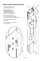
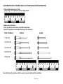
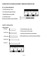
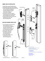
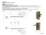
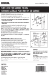
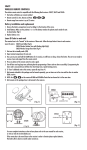
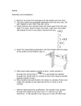
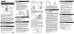
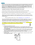
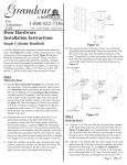
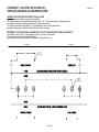
LSDXCR2267 (LATCH SET DX CR3 2260 357)
TEMPLATE AND INSTALLATION INSTRUCTIONS
RFQDXCR3
WARNING: CHECK DOOR PROFILE PRIOR TO INSTALLATION
You will require a profile wide enough for proper installation.
With the door closed, the minimum inside door profile width is 1-3/4” from the edge of the door frame (glass side) to
the edge of the door jamb or metal door frame (z-bar), which ever is narrower.
The minimum outside door profile width is 2-1/8” from the edge of the door frame (glass side) to
the edge of the door jamb or metal door frame Z-bar), which ever is narrower.
DETERMINE IF YOUR STORM DOOR IS HINGED RIGHT OR LEFT FOR PROPER USE OF DRILLING TEMPLATE
From outside of door, looking in, if the hinges are on your left, your door is left handed.
If the hinges are on the right, it is a right handed door.
Ensure that the inside latch and deabolt do not interfere with the prime door lock.
cutting line
2"
cutting line
1/16"
8 PLCS
1 5/32"
29/32"
27/32"
5/16"
6 PLCS
5 1/8"
1"
1 3/4"
1 3/4"
PAGE 1 OF 5
TEMPLATE PLACEMENT AND DRILLING INSTRUCTION
1. Fold the template on the dotted line to 90
according to the handedness (left or right).
JAMB
DOOR
2. With the door in closed position,
place folded template on inside of door
so that the SIDE A is against the jamb
or metal z-bar, which ever projects out farther;
and SIDE B is on the inside surface of door.
3. Use a center punch to mark the position
of 6 holes on the inside surface of door on SIDE B.
Mark the position of 4 holes on the jamb on SIDE A (for strikes).
4. Using a 5/16” drill bit, drill 6 holes straight through
door from SIDE B.
A
5. Using a 1/16"drill bit, drill 4 pilot holes with depth of 1"
on the jamb on SIDE A.
DETAIL A
PAGE 2 OF 5
LSDXCR2267 HANDLE SPINDLE AND LATCH SCREW SELECTION INSTRUCTION
1. Print out this sheet using 1:1 scale.
(verify using a ruler against the print out image below)
2. Measure door thickness.
3. Over lay spindles and screws on top of the image below.
4. Select the spindle and screws that match your door thickness.
DOOR THICKNESS
SCREW
SPINDLE
1" TO 1 1/8"
1 1/4" TO 1 3/8"
1 1/2" TO 1 5/8"
1 3/4" TO 1 7/8"
2" TO 2 1/4"
Now that the handle spindle and latch screws are selected and ready for installation.
PAGE 3 OF 5
LSDXCR2267 KEYLOCK SPINDLE AND DEADBOLT SCREW SELECTION INSTRUCTION
KEY LOCK SPINDLE PREPARATION
1. Print this sheet using 1:1 scale.
2. Over lay flat spindle against the image.
3. Mark door thickness on the spindle.
4. Cut off at the mark line.
Now the key lock spindle is ready for installation.
PLACE SPINDLE HERE
DEADBOLT SCREW SELECTION
DOOR THICKNESS
1" TO 1 1/8"
1 1/4" TO 1 3/8"
1 1/2" TO 1 5/8"
1. Print out this sheet using 1:1 scale.
2. Over lay screws on top of the image.
3. Select the screws that match your door thickness.
Now the deadbolt screws are selected and ready for installation.
1 3/4" TO 1 7/8"
2" TO 2 1/4"
PAGE 4 OF 5
HANDLE AND LATCH INSTALLATION
1. Arrange handle, housing, and backplate as shown.
2. Place spindle & spring in between housing & backplate.
3. Place the outside handle assembly (from step 1&2) on door.
(If your door thickness is not standard then:
The spindle should project through inside
of door a max of 3/8" and min of 1/4".
You may have to cut off spindle.)
4. Place the latch on inside of door, fasten with
two machine screws. Do not over tighten screws.
Fasten the backplate with the tie down screw.
5. Place the latch strike (use shim if required) on jamb,
aligning with the pilot holes on jamb,
fasten with two tapping screws.
KEY LOCK SPINDLE
KEY LOCK
DEADBOLT
STRIKE
DEADBOLT
HANDLE
HANDLE
SPINDLE
&SPRING
KEY LOCK & DEADBOLT INSTALLATION
1. Insert the flat spindle into the back of key lock.
Ensure spindle bottoms into key lock.
(If your door thickness is not standard then:
The spindle should project through
inside of door a max of 1" and min of 3/4".
Cut off the spindle beyond that length.)
2. Place key lock on outside of door.
3. Place deadbolt on inside of door,
fasten with two machine screws.
Do not over tighten screws.
4. Place the strike for deadbolt on jamb,
align with pilot holes on jamb,
fasten with two tapping screws.
LATCH
LATCH
STRIKE
TIE DOWN SCREW
MAX 3/8"
MIN 1/4"
MAX 1"
MIN 3/4"
Thank you for your purchase.
If you require any information or installation assistance,
please contact our customer service.
Monday to Friday 7:30 am -3 pm (Eastern Time)
Tel: 1-800-361-2236 x 230
e-mail: [email protected]
Updated instructions (if applicable) can be found at www.idealinc.com
IDEAL SECURITY INC.
LASALLE, QUEBEC, CANADA
CORAOPOLIS, PA., USA
Handle Spindle Projected Length
Deadbolt Spindle Projected Length
PAGE 5 OF 5