1
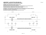
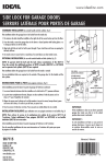
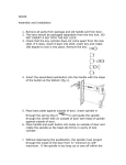
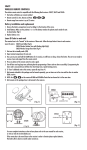
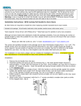
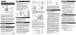
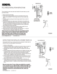
HK357DB05
Template and installation instructions
Warning:
Check door profile prior to installation
You will require a profile wide enough for proper installation.
With the door closed, the minimum outside door profile width is 2.5” from the edge of the door frame (glass side) to the edge of the door jamb
or metal door frame (z-bar), which ever is narrower. (Fig 1)
The minimum inside door profile width is 2.125” from the edge of the door frame (glass side) to the edge of the door jamb or metal door frame (Z-bar),
which ever is narrower. (Fig 2)
Determine if your storm door is hinged right or hinge left for proper use of drilling template
From outside of door, looking in, if the hinges are on your left, your door is left handed. If the hinges are on the right, it is a right handed door.
Ensure that the inside paddle does not interfere with the prime door lock.
cutting line
cutting line
1.943
1.451
.345
.061
.750
.910
.854
.875
1.323
Fig 1
.312
2.5"
.875
1.750
2.125"
Fig 2
PAGE 1 OF 5
RFQHK357DB05
Template Placement and Drilling Instructions
1. Fold the template on the dotted line to 90
according to the handedness (left or right).
DOOR
OUTSIDE
JAMB
DOOR
GLASS
2. With the door in closed position,
place folded template on inside of door
so that the SIDE A is against the jamb
or metal z-bar, which ever projects out farther;
and SIDE B is on the inside surface of door.
3. Use a center punch to mark the position
of 3 holes on the inside surface of door on SIDE B.
Mark the position of 3 holes on the jamb on SIDE A (for strikes).
4. Using a 5/16” drill bit, drill 3 holes straight through
door from SIDE B.
5. Using a 1/16"drill bit, drill 3 pilot holes with depth of 1"
on the jamb on SIDE A.
6. Use a chisel to cut a rectangle hole 3/8" deep
on the jamb on SIDE A within the hatched area.
CHISEL OUT
THIS AREA
TO 3/8" DEEP
INSIDE
PAGE 2 OF 5
SPINDLES AND SCREWS SELECTION CHART
HANDLE SPINDLE SELECTION
LATCH SCREW SELECTION
DOOR THICKNESS
DOOR THICKNESS
1"
1 1/4"
1"
1 1/4"
1 1/2" & 1 3/4"
1 1/2"
2" & 2 1/4"
1 3/4"
2"
2 1/4"
1. Print out this sheet using 1:1 scale.
Verify scale using a ruler.
2. Over lay screws on top of the image.
3. Select the screws that matche your door thickness.
Now the latch screws are selected and ready for installation.
1. Print out this sheet using 1:1 scale.
Verify scale using a ruler.
2. Over lay handle spindle on top of the image.
3. Select the spindle that matches your door thickness.
Now the handle spindle is selected and ready for installation.
PAGE 3 OF 5
Handle, Deadbolt, & Latch Installation
1. Rotate the outside handle to the left or right according to your door handedness.
2. Insert a handle spindle completely into the center hole of the outside handle from the back side. The spindle locks the handle in place.
3. Place the outside handle assembly on door.
(If your door thickness is not standard then:
The spindle should project through inside of door a max of 1/2" and min of 1/4". You may have to cut off spindle.)
4. Place the deadbolt and latch on inside of door, fasten with two machine screws. Do not over tighten screws.
Install the self-drilling screw at the bottom of the deadbolt.
5. Place the strike on the jamb, align with pilot holes, fasten with three tapping screws.
You might need a shim plate if strike is too far away from latch.
SHIM FOR STRIKE
IF REQUIRED
STRIKE
HANDLE
STRIKE
MOUNTING
SCREWS
SPINDLE
LATCH
LATCH
MOUNTING
SCREWS
1/2" max
1/4" min
Thank you for your purchase.
If you require any information or installation assistance,
please contact our customer service.
Monday to Friday 7:30 am -3 pm (Eastern Time)
Tel: 1-800-361-2236 x 230
e-mail: [email protected]
Updated instructions (if applicable) can be found at www.idealinc.com
IDEAL SECURITY INC.
LASALLE, QUEBEC, CANADA
CORAOPOLIS, PA., USA
SELF DRILLING SCREW
DEADBOLT
PAGE 4 OF 5
DIMENSIONS
1.654
2.431
2.078
1.008
1.319
4.449
4.567
2.406
.674
.444
.500
1.091
1.5
1.465
.696
2.149
3.948
PAGE 5 OF 5