1
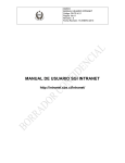
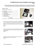
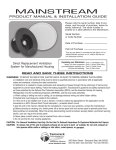
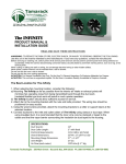
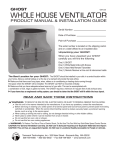
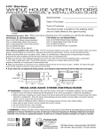
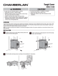
TC1000
TCPG-2
All Weather VENTILATOR
PRODUCT MANUAL & INSTALLATION GUIDE
Serial Number
Date of Purchase
Point of Purchase
The serial number is located on the shipping carton
and on a label affixed to the upper housing.
Unpacking your TC: When you have unpacked your TC carefully you will find the following:
TC1000-T
One (1) TC1000-T All Weather Ventilator
One (1) Line Voltage Thermostat
TC1000-H
One (1) TC1000-H All Weather Ventilator
One (1) Wall Switch (SPST)
The TC 1000 can be installed in one of three ways:
• In a glazing system - The TC1000 must be installed by a qualified installer. If it is to be installed in a double glazing
system, an internal spacer to match the thickness of the glazing must be factory installed, or one fabricated on the site.
If a spacer is site fabricated, please note that it must be installed UNDER the fan.
• On a conventional or stress skin panel roof - The TC1000 will have no internal spacer - its flanges will be 1/4" thick.
After a 12 1/2" x 27" rough opening is cut through the roof, a sheet metal "thimble" should be installed to line the opening.
The fan should be installed using standard skylight flashing techniques. Installing a grille is recommended to
cover the opening in the ceiling.
• On a vertical wall - We strongly suggest installing a piece of flashing above the TC1000 to sweep the rain away before
it hits the edge of the fan.
READ AND SAVE THESE INSTRUCTIONS
WARNING: TO REDUCE THE RISK OF FIRE, ELECTRIC SHOCK, OR INJURY TO PERSONS, OBSERVE THE FOLLOWING:
Use this unit in the manner intended by the manufacturer. If you have any questions, contact the manufacturer.
Before servicing or cleaning unit, switch power off at service panel and lock service panel to prevent power from being
switched on accidentally. When the service disconnect cannot be locked, securely fasten a prominent warning
device, such as a tag, to the service panel.
When cutting or drilling into wall or ceiling, do not damage electrical wiring or other hidden utilities.
Never place a switch where it can be reached from a tub or shower.
Do not use this fan over a tub or shower.
Do not use this fan over cooking appliances.
WARNING: To Reduce The Risk of Fire or Electric Shock, Do Not Use This Fan With Any Solid-State Speed Control Device.
CAUTION: For General Ventilation Use Only. Do Not Use To Exhaust Hazardous Or Explosive Materials And Vapors
LIKE US ON
FACEBOOK
FOLLOW US
ON TWITTER
320 Main Street • Buzzards Bay, Ma 02532
508-759-4660 / 800-222-5932 / Fax 508-759-6001
Installation
Installing the TC1000 in a Wall
You will need the following items:
• Two pieces of 2x stock to match your existing framing
• Saw to cut the hole in the wall
• Hammer or screw gun to attach the blocking to the existing frame
• Phillips head screwdriver to attach the grille
• Weather strip material
• Low expansion spray foam sealant
Add framing as
shown to create
a box of 12 1/2”
x 27. This box
will act to hold
the unit as well
as creating a
plenum for air
movement.
Fig. 1
16” OC
1. Create a box to hold the unit (Fig. 1).
2. Remove the sheathing that covers the box.
3. Attach TC1000, screwing through the mounting flange.
4. Install exterior finish materials over the mounting flange.
Note: additional flashing may be required above the unit to divert rain.
5. Remove any interior materials covering the box.
6. Install interior finish materials to trim the frame.
7. Attach grille (optional) to finish installation.
Wiring
Important - Wiring the TC is different than a normal ON/OFF fan. The TC damper is motorized and
requires a constant source of power; power to open and power to close. The TC1000-T comes with a wall
mounted, line voltage thermostat. This thermostat is surface mounted and should be positioned at eye
level. The TC1000-H comes with a SPST wall switch that is mounted in a standard single gang electrical
box. A 3-wire will need to be run between the control point and the TC regardless of the model.
Please follow the instructions carefully. It is recommended that the wiring of the TC be done by
a licensed electrician in accordance with local code requirements.
Be sure to turn off power before wiring the TC1000
Please note that if the TC1000 is installed in an enclosure
with a spa or hot tub or pool, a humidistat (optional item)
as well as a thermostat must be installed.
We strongly recommend a non-chlorine based
chemical for over the water applications.
Single and
Multiple TC’s
with Single
Control
Single and
Multiple TC’s
with Dual
Control
Be sure to tighten the strain relief prior to replacing the baseplate.
Troubleshooting
The most common installation error is caused by incorrect
wiring. Be sure that each of the 3 wires in the TC1000
are connected individually. There is a 30 second delay
after the control is activated and the damper opens
before the fan motors start.
Care
All the motors in the TC are permanently sealed and do not
require oiling. To keep dirt, dust and debris from the fans we
recommend that you periodically remove the grille from
within the living space and dust the fan blades. Please
remember to make sure that the electrical circuit is
OFF before dusting the fan blades.
Specifications
Power Requirements . . . . . . . . . . . . . . . . . . . . . . . . . . . . .120 VAC, 60 HZ, 110 watts, 1.5 A
Airflow . . . . . . . . . . . . . . . . . . . . . . . . . . . . . . . . . . . . . . . . . . . . . . . . . . .800 CFM @ .1 high
Effective R value . . . . . . . . . . . . . . . . . . . . . . . . . . . . . . . . . . . . . . . . . . . . . . . . . . . . .R 10.0
Rough opening . . . . . . . . . . . . . . . . . . . . . . . . . . . . . . . . . . . . . . . . . . . . . . . . . .12.5” x 27”
Cover Height above flange . . . . . . . . . . . . . . . . . . . . . . . . . . . . . . . . . . . . . . . . . . . . . . . .5”
Warranty . . . . . . . . . . . . . . . . . . . . . . . . . . . . . . . . . . . . . . . . . . . . . . . . . . . . . . . . .3 Years
LIMITED WARRANTY If, within the period of three years from the date of purchase, the TC1000 (the Product) is defective
or malfunctions in normal home use, Tamarack Technologies, Inc. will repair or replace the Product, at its discretion. Customer
is responsible for shipping charges.
CONDITIONS, EXCLUSIONS, AND LIMITATIONS
This Warranty is subject to the following conditions, exclusions and limitations:
THIS WARRANTY DOES NOT COVER PROBLEMS RESULTING FROM INSTALLATION, OPERATION OR MAINTENANCE THAT HAS BEEN UNDERTAKEN OTHER THAN IN ACCORDANCE WITH THE INSTRUCTIONS. THIS WARRANTY DOES NOT COVER PROBLEMS RESULTING FROM
DEFECTS IN OR CAUSED BY ASSOCIATED EQUIPMENT (FURNACES, SOLARIA, ETC.); FROM REPAIRS OR MODIFICATIONS ATTEMPTED
BY PERSONS OTHER THAN TAMARACK TECHNOLOGIES, INC.; FROM ABUSE, ACCIDENTAL OR SHIPPING DAMAGE OR ACTS OF GOD. THIS
WARRANTY DOES NOT APPLY TO THE PRODUCT USED OUTSIDE THE UNITED STATES, ITS TERRITORIAL POSSESSIONS, AND CANADA.
EXCEPT AS SET FORTH ABOVE, NO EXPRESS OR IMPLIED WARRANTY IS GIVEN OR AUTHORIZED BY TAMARACK TECHNOLOGIES, INC.
AND ALL OTHER SUCH WARRANTIES ARE EXPRESSLY DISCLAIMED. ANY WARRANTY OR MERCHANTABILITY OF FITNESS FOR ANY PARTICULAR PURPOSE SHALL BE LIMITED TO THE WARRANTY HEREUNDER. MOREOVER, ANY LIABILITY OF TAMARACK TECHNOLOGIES,
INC. FOR THE PRODUCT SHALL BE LIMITED TO THE REPLACEMENT VALUE OF THE PRODUCT. IN NO EVENT SHALL TAMARACK TECHNOLOGIES, INC. BE LIABLE FOR ANY INCIDENTAL DAMAGES OR FOR ANY CONSEQUENTIAL PROPERTY OR COMMERCIAL DAMAGES, IRRESPECTIVE OF THE CAUSE THEREOF, OCCURRING EITHER DURING OR AFTER THE WARRANTY PERIOD, INCLUDING WITHOUT
LIMITATION ANY DAMAGES TO ANY PART OF A BUILDING OR ITS CONTENTS. NOTE: SOME STATES DO NOT ALLOW THE EXCLUSION OR
LIMITATION OF INCIDENTAL OR CONSEQUENTIAL DAMAGES AND SOME STATES DO NOT ALLOW LIMITATIONS ON HOW LONG AN IMPLIED
WARRANTY LASTS, SO THE ABOVE LIMITATIONS OR EXCLUSIONS MAY NOT APPLY TO YOU. THIS WARRANTY GIVES YOU SPECIFIC LEGAL
RIGHTS AND YOU MAY ALSO HAVE OTHER RIGHTS THAT VARY FROM STATE TO STATE. PROOF OF PURCHASE REQUIRED.
320 Main Street • Buzzards Bay, Ma 02532
508-759-4660 / 800-222-5932 / Fax 508-759-6001