1
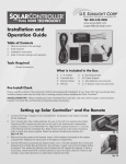
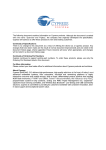
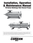
™ Tel: 866-446-0966 Installation and Operation Guide Table of Contents 1. 2. 3. 4. What is included in this package Tools required Installation instructions Solar Controller settings and operation www.ussunlight.com [email protected] A B C E D F Tools Required - Philips Screwdriver What is Included in the Box A 2 - 8’ Cables B Controller Box C Remote Holder DRemote E F G H 6 - Mounting Screws AC Power Adapter 2 - AAA batteries (not pictured) 2 - 6” long tie wraps (not pictured) Pre-Install Check Please read the entirety of the instructions before proceeding with installation. If your Solar Attic Fan has already been installed, please make sure the Solar Fan is working properly before installing the Solar Controller. INSTALLATION TIPS - Before installing the Solar Controller Box in the attic, test and confirm proper communications between Controller Box and Remote by following setup procedures. Setting up Solar Controller and the Remote 1. Connect AC Power Adapter to the Controller Box. Temperature and relative humidity will be displayed. 2. The Controller Box has 2 slide switches, the one on the left is for selecting the Radio Frequency (RF) channel and the one on the right is for selecting the temperature readout in Celsius (°C) or Fahrenheit (°F). Align the RF channel (choice of 1,2 and 3) of the Remote with the Controller Box. Both of them must be on the same channel in order to send and receive signals. Select the desired temperature readout unit. (fig 1a & 1b) fig. 1a 3. Remove the back panel of the Remote. Insert 2 AAA batteries (included) in the battery compartment. Replace the back panel of the battery compartment. 4. Test the Remote by pressing the Status button once. This will establish the connection between the Controller Box and Remote. You will hear a “beep” every time the Status button is pressed. This verifies the Remote and Controller Box RF signals are aligned. If there is not a beep, check that the RF channel selector is set to the same channel. If there is still no beep, move both devices to an alternative channel and retry. fig. 1b Remote Diagram Attic Temperature House Power Attic humidity Fan Mode Battery Compartment Solar Power Thermo Switch Status Thermo Switch Channel Switch Installing Solar Controller If your Solar Controller came bundled with an attic fan, install the fan first following the instructions included for that model of fan. When the installation of the fan is complete, install Solar Controller. Note that Solar Controller is designed to work with U.S. Sunlight Solar Attic ventilation products. DO NOT ATTEMPT to connect Solar Controller to other solar fans. Solar Controller can be installed with or without the use of house electricity: Standard Installation When implementing the standard installation, Solar Controller will run only on power generated by the solar panel and will provide these functions: 1. Reads attic temperature and relative humidity and displays them on the Controller Box and Remote 2. Monitors fan and solar panel working conditions 3. Allows user to enable or disable Thermo Switch on the Remote (Note: These functions will be active only when the sun is available to generate electricity from the solar panel) Installation with use of House Electricity Installing Solar Controller with the AC Power Adapter will provide these additional benefits: 4. Extends fan operation into the evening hours 5. Allows fan to operate when no sun is available 6. Intelligently limits the amount of house electricity to be used for adequate ventilation Copyright 2011 US Sunlight Corp, Inc. SC10 C01 ver 4 Standard Installation 1. Bring the complete Solar Controller Kit, including the Remote and Controller Box, to the attic. 2. Check and make sure the Thermo Switch on the back of the Remote is set to the OFF position 3. Install the Controller Box on a nearby rafter close to the underside of the roof with the provided mounting screws. (fig 2a & 2b) The Controller Box has vents on either side of the housing that allow the temperature and humidity sensors to work, so it is important to locate the Controller Box with at least 1 inch of space between it and the underside of the roof. (fig 3 & 4) For best results, locate the Controller Box near the fan opening as fig. 2a shown. Mounting within 2 to 3 feet of the motor is recommended. (fig 5) fig. 2b fig. 3 fig. 4 fig. 5 4. Unplug the 2 wire leads (red and black) from the motor. (fig 6) If your fan came with a thermal switch, unplug the wire coming in from the solar panel to the switch. (fig 7) The Controller Box will be replacing the function of this switch. You will not need the thermal switch and it can be discarded. fig. 6 fig. 7 5. Take one 8’ cable (included) and plug the female leads into the motor (red to red and black to black) (fig 8) and connect the male leads to the fan connectors on the Controller Box. (fig 9) Note: It is important to connect the Controller Box to the motor BEFORE connecting to the solar panel. fig. 8 fig. 9 6. Take the other 8’ cable and connect the female leads to the solar connectors on the Controller Box (red to red and black to black) and connect the male leads into the female leads coming from the solar panel. (fig 10) fig. 10 WARNING: Fan will begin running as soon as sun hits the solar panel - keep fingers clear of the fan blades. 7. The cable connectors have been designed to prevent incorrect connection. You will need to confirm the red wires are connected to the red wires and the black wires to the black wires, as shown. (fig 11) 8. Provided there is sunlight to the solar panel, the LCD display is now activated and will read the current attic temperature and relative humidity. When the Solar Controller logic detects the fan in operation, the fan and solar LEDs will light up accordingly. This will take approximately 30 seconds. 9. Press the Status button on the Remote to activate Solar Controller. Fan should be running now if solar power is available. Press the Status button again to update the fan’s operation status. (fig 12) 10. Use the included tie wraps and 1/4” or 1/2” coaxial staples, available from your local hardware store or builders’ supply, to secure the wiring harness to the rafter. (fig 13a & 13b) fig. 11 fig. 12 fig. 13a fig. 13b Solar Controller is now installed and running with power generated by the solar panel. Installation with Use of Optional House Electricity To utilize the house electricity option with Solar Controller, connect the Controller Box to an AC outlet with the included AC Power Adapter. You may want to consult an electrician to decide on the best method for your situation. The AC Power Adapter works on a standard 110V outlet. DO NOT USE AN EXTENSION CORD FOR THIS CONNECTION. 1. Complete steps 1~10 in the standard installation. 2. Temporarily disconnect wiring to the solar connectors at the Controller Box. 3. The AC Power Adapter comes with 4.5 ft. of cord. Verify the power source (outlet) is located within that distance. (fig 14) 4. Connect the AC Power Adapter to the House Power/DC 12V port on the Controller Box as shown. (fig 15) 5. Plug the AC Power Adapter into the power source (outlet). (fig 16) The Controller Box will display attic temperature and relative humidity in a few seconds. 6. Press the Status button on the Remote to activate Solar Controller. The fan will be running now. Press the Status button again to update the operation status. (refer back to fig 12) 7. If necessary, use 1/4” or 1/2” coaxial staples to secure the wire to the rafter. (fig 17) 8. Reconnect the wiring in step 2 to the solar connectors at the Controller Box. fig. 15 fig. 16 Solar Controller will now utilize the solar panel and house electricity to optimize fan operation. fig. 14 fig. 17 Solar Controller Remote The Remote has one Status button on the front below the LCD display, and a Thermo Switch selector on the back. Front of the Remote - Channel Setting There are 3 available RF channels. Select the same RF channel for the Controller Box and Remote. The RF channel ID must match the Controller Box and Remote in order to have information available. Front of the Remote - Status Button When the Status button is pressed, a beep will sound from the Controller Box to signify a proper connection between the Controller Box and Remote. The Remote’s LCD display will show the following information: • Attic Temperature • Attic Relative Humidity • Fan Mode - ON, OFF, INTERMITTENT or FAILURE • House Power - ON • Solar Power - ON The status will be displayed for approximately 20 seconds. Press the Status button again to refresh the information after 20 seconds. Note that it is important to make sure the RF channel is the same between the Controller Box and Remote. If there is no beep sound after pressing the Status button, no connection has been made with the Controller Box and the LCD display will go blank. Check the following if there is no display on the Remote after pressing the Status button: • Batteries have been installed. Replace if necessary • RF channel is properly aligned between the Controller Box and Remote • Solar Controller wire connections are correct • AC Power Adapter is connected to the Solar Controller for after dark operation • If the problem persists, contact U.S. Sunlight Customer Service at 1-866-446-0966 Back of the Remote - Thermo Switch selector (ON or OFF) The Thermo Switch allows the user to engage or disengage the temperature control. U.S. Sunlight recommends the Thermo Switch be set to ON in warm climates and to OFF in cold climates where sustained below freezing temperatures may occur. When Thermo Switch is set to: • ON mode - Fan will only be turned on when attic temperature reaches 80°F and power is available. Once on, fan will stop when temperature drops below 77°F • OFF mode - Fan will be turned on when power is available, regardless of attic temperature After making a change to the Thermo Switch on the Remote, 1. Click the Status button to send the command to the Solar Controller 2. Wait 5 seconds for the Solar Controller to change the fan operation 3. Click the Status button again to read the current fan operation status Humidity Control - ALWAYS ENABLED The relative humidity sensor is always enabled (the user cannot disable the sensor). The fan will be turned on when attic relative humidity reaches 75%, regardless of attic temperature. The fan will turn off when relative attic humidity drops to 65%. Power Source 1. Whenever available, solar power is the default power source. On a typical day with proper sunlight, the fan will operate until sunset. 2. If solar power is not available, the fan will not operate unless the Solar Controller is installed with the AC Power Adapter connected to house electricity. The fan will continue operation in the following pre-set mode for 6 hours: i. ON for 8 minutes and OFF for 22 minutes in a 30-minute period. This is the most effective air circulation frequency to keep the attic temperature close to the outside temperature ii. The fan will run for a maximum of 6 hours on intermittent house electricity. iii. The fan will run on solar power whenever solar power becomes available again. iv. After 6 hours of running on intermittent house electricity, the fan will be turned off for up to 12 hours, then turned back on, assuming solar power is not available during this period of time. Summary: Primary Power Source Solar Fan with Solar Controller WITHOUT AC Adapter connected Solar Fan with Solar Controller WITH AC Adapter connected Daytime - with sufficient solar power Solar power Solar power Evening after sunset No power available Intermittent house electricity for 6 hours Note that the primary power source is always SOLAR. If solar power is not available during the daytime, the primary power source will switch to house electricity (if the Controller Box is connected to house electricity) for up to 6 hours or until solar power becomes available. Refer to this summary to interpret the LCD display and the fan’s operating status: LCD Display House Power Solar Power Fan (Blank) ON ON (Blank) ON ON (Blank) OFF ON-Intermittent Operation Summary • • Solar power is available Fan is running • • • • • Solar power is available Fan is not running Attic Temperature is <80°F Thermo Switch could be ON To run fan, switch Thermo Switch to OFF then press the Status button twice • • • Solar power is not available Fan is powered by house electricity Fan is running intermittently, currently in the 8-min ON mode of the 6-hour cycle LCD Display House Power ON ON (Blank) ON Solar Power (Blank) (Blank) ON (Blank) Fan Operation Summary • • • Solar power is not available Fan is powered by house electricity Fan is running intermittently, currently in the 22-min OFF mode of the 6-hour cycle • • • • Solar power is not available Fan is powered by house electricity Fan is in the 12-hour OFF mode Fan will restart when solar power becomes available, or at the end of the 12-hour OFF mode Failure • • • House electricity is available Fan is not running Possible problems - Loose wiring - Motor Failure - Solar Controller Failure Failure • • • Solar power is available Fan is not running Possible problems - Loose wiring - Motor Failure - Solar Controller Failure Intermittent OFF Multiple Fan Setup - 3 or less fans Assign one of the three available channels to each of the Solar Controllers. A beep sound will come from the Controller Box that is communicating with the Remote. Each paired set of a Controller Box and Remote should be set to different RF channels. Therefore, each pair will have the Controller Box and Remote set to the SAME RF channel but be DIFFERENT than the other Controller Boxes and Remotes installed in the same attic. Do not assign the same RF channel to 2 or more Solar Controllers. The user can use the same Remote to control all 3 fans (if applicable) by selecting the correct RF channel. 4 or more fans Consult with U.S. Sunlight Customer Service by calling 1-866-446-0966. Additional Information Please visit our website at www.ussunlight.com for additional product information and FAQs. Or call 1-866-446-0966 and one of our Customer Service Representatives will be able to help you. W A R R A N T Y Manufacturer’s Limited Warranty U. S. Sunlight Corp. (“Manufacturer”) warrants that certain of its product components are free from defects of workmanship and/or materials for a period of time commencing on the date of original purchase and continuing as noted hereafter: (a) Solar Controller unit for a period of one (1) year (b) Solar Controller remote for a period of one (1) year. Disclaimer Except as expressly set forth herein, all Manufacturer’s products, including components thereof, are sold “AS IS” without warranty of merchantability, fitness for intended purpose, or other warranty, express or implied. In no event shall Manufacturer be liable for the loss of profits, indirect, special, incidental, consequential or other similar damages, including but not limited to any claim or demand arising out of the installation, furnishing, or functioning of a product or use by purchaser or any third party. The warranty terms and conditions detailed above do not extend to misuse, neglect, abuse, alteration, exposure to extreme weather conditions, lightning strikes, physical damage to any product, or damages caused by transportation or installation of any product. Manufacturer explicitly does not warrant any labor, shipping, or service fees incurred by purchaser for the replacement, repair, or exchange of any product or product components claimed under the above warranty terms and conditions. Warranty Claims Warranty claims shall be submitted in writing to Manufacturer at its principal place of business. Claims shall include a copy of the original purchase invoice, purchaser’s name, address, telephone number, and e-mail address, and such other particulars as are necessary to describe the claimed defect. If requested by Manufacturer, purchaser shall ship the claimed defective component(s) to Manufacturer’s principal place of business, FOB destination, freight prepaid, for evaluation. As to any product component determined by Manufacturer to contain a defect covered by its warranty, Manufacturer reserves the right, at its discretion, to repair or replace the defective component, or rebate a portion of the purchase price prorated based on the balance of the warranty term. General This limited warranty contains all of the terms and conditions of Manufacturer’s warranty of the purchased product and its components. No representation, arrangement, or agreement not appearing herein shall be binding on Manufacturer. This limited warranty is issued in and shall be governed by the laws of the State of California. C U T H ER E R E G I S T R A T I O N W E WOU LD LOV E TO HE AR F RO M YO U! To register please visit our website: www.ussunlight.com or simply fill out this form and mail to: 923 Tahoe Blvd. Suite 110 | Incline Village, Nevada 89451 Name ________________________________________________________Phone________________________________________ Address ___________________________________________________________________________________________________ City __________________________________________________________ State ______________ Zip _____________________ Email _____________________________________________________ Would you like to be included in our newsletter? Y or N Product Name __________________________________________ Date of Purchase ___________________________________ Purchased From ______________________ Name of Installer _____________________________________________ (self Phone # of Installer ___________________ How satisfied are you with the install? Not Satisfied Somewhat ) Very Comments ____________________________________________________________________________________________