1
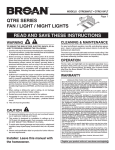
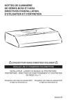
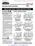
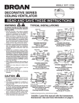
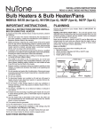
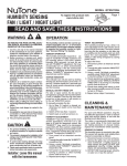
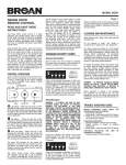
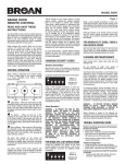
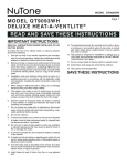
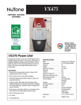
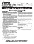
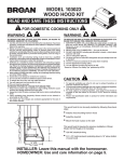
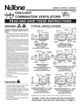
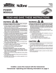
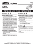
GABLE-MOUNT POWERED ATTIC VENTILATOR MODEL 353 MODEL 35316 READ AND SAVE THESE INSTRUCTIONS WARNING TO REDUCE THE RISK OF FIRE, ELECTRIC SHOCK, OR INJURY TO PERSONS, OBSERVE THE FOLLOWING: 1. Use this unit only in the manner intended by the manufacturer. If you have questions, contact the manufacturer at the address or telephone number listed in the warranty. 2. Before servicing or cleaning unit, switch power off at service panel and lock the service disconnecting means to prevent power from being switched on accidentally. When the service disconnecting means cannot be locked, securely fasten a prominent warning device, such as a tag, to the service panel. 3. Installation work and electrical wiring must be done by a qualified person(s) in accordance with all applicable codes and standards, including fire-rated construction codes and standards. 4. Sufficient air is needed for proper combustion and exhausting of gases through the flue (chimney) of fuel burning equipment to prevent backdrafting. Follow the heating equipment manufacturer's guidelines and safety standards such as those published by the National Fire Protection Association (NFPA), and the American Society for Heating, Refrigeration and Air Conditioning Engineers (ASHRAE), and the local code authorities. 5. When cutting or drilling into wall or ceiling, do not damage electrical wiring and other hidden utilities. 6. The wiring must be permanent. DO NOT USE AN EXTENSION CORD! Use 14 GA. MINIMUM copper wire. Although the Powered Attic Ventilator may be wired directly to power, we advise that some type of shut off switch be installed in the line. Please see the section on electrical wiring for suggested wiring diagrams and instructions. 7. This unit must be grounded. CAUTION 1. For general ventilating use only. Do not use to exhaust hazardous or explosive materials or vapors. 2. To avoid motor bearing damage and noisy and/or unbalanced impellers, keep drywall spray, construction dust, etc. off power unit. TOOLS & MATERIALS REQUIRED Screwdrivers (Slotted & Phillips) Hammer Ruler Pencil Electrical supplies (to comply with codes) Nails PREPARE THE VENTILATOR 1. Unpack the ventilator and find: 1 - power unit with wiring box 4 - angle brackets 8 - sheet metal screws CAUTION 3. This unit has an unguarded impeller. Do not use in locations readily accessible to people or animals. 4. Fan is equipped with a thermostat which may start fan automatically. To reduce risk of injury or electric shock while servicing and cleaning unit, switch power off at service panel and lock service panel to prevent power from being switched on accidentally. When the service disconnecting means cannot be locked, securely fasten a prominent warning device, such as a tag, to the service panel. 5. Home Ventilating Institute (HVI) recommends one square foot of open air inlet per 300 cfm of fan capacity. The best location for these air intake vents are under the eaves with direct access to the attic. Vents for attic side wall installations should be placed at the end of the house opposite the installed ventilator. Failure to provide these intakes could cause natural-draft gas appliances to backdraft. 6. Your attic installation will create a screened opening into your attic space. During a heavy rainstorm there could be a light spray of rain into this attic space. This is a normal condition with all attic ventilators and will not cause any damage to the structure.We recommend that you do not store any valuable articles directly under the fan opening in the gable. During extreme rain and wind storms you may want to turn on your attic ventilator to prevent excess mositure accumulaltion in your attic. 7. Records show, under ideal conditions, exposed galvanized steel can remain rust free up to 100 years. For best protection, the exposed portion of the roof sheet should be painted, especially in areas of unusually high industrial air pollution. Follow paint manufacturer’s instructions for good adhesion. 8. This ventilator is intended for Gable installation. The Broan Models 350, 355, 356 & 358 Roof Mount Ventilators are available for roof mount applications. 9. Please read specification label on product for further information and requirements. 2. Fasten the four (4) angle mounting brackets to the housing using the eight (8) sheet metal screws provided. Position the bracket flush with the edge of the housing band. A close fit between ventilator and louver will minimize air recirculation. INSTALL THE VENTILATOR 1. The ventilator is designed to mount behind existing louvers. Find the type of louver you have in the examples below. If no louver exists, one must be installed. Louver should be mounted in the center of the upper portion of the gable as high as possible. For maximum efficiency, the area of the louver should be greater than the outlet area of the ventilator. The ventilator can also be mounted off-center in an odd shaped louver. There is some loss in fan output because the louver blocks some of the air flow. Metal louvers have more open area than wood louvers and usually allow more air flow. When installing the ventilator behind louvers, you should seal off any louver area not covered by the ventilator housing band to prevent air leakage and recirculation. We suggest you mount the ventilator on a piece of plywood for best sealing. Allow at least one square foot of air intake area for every 300 CFM of ventilator capacity. CAUTION! When installing louvers or shutters, do not remove any existing structural members without providing alternate support members. On large triangular louvers, mount to the frame or nail boards to the frame to provide a mounting surface for the ventilator. For the most effective installation, enclose the louver area not covered by the fan, with plywood or similar material. The ventilator can be mounted flush to a rectangular type louver by fastening through the mounting brackets to the frame of the louver. On a wide louver the brackets can first be fastened to the backside of two boards of the appropriate length and these boards can then be fastened to the frame. Louvers that are smaller than the ventilator outlet will restrict air delivery. When this condition exists, a chamber should be built to properly direct the air through the louvers. A typical example of the suggested construction is shown. With a narrow louver mounted between studs on 16” centers, two of the brackets can first be mounted to the backside of boards and the boards and other brackets nailed to the studs. An automatic shutter, Model 433, may also be installed to provide the necessary outlet for the fan. Installation instructions are provided with the Model 433 shutter. 2 WIRE THE VENTILATOR BLACK BLACK TO MOTOR 1. Remove the thermostat wiring box cover plate. Bring the power cable at least 6” into the thermostat wiring box. Fasten to box with appropriate connector. GROUND TO SWITCH BOX HUMIDISTAT WHITE BLACK VENTILATOR WIRING BOX BLACK THERMOSTAT WHT THERMOSTAT BY-PASS SWITCH WHT MOTOR RED GRD TO HUMIDISTAT BLK GROUND TO SWITCH BOX GRD GROUND TO SWITCH BOX RED BLACK MOTOR BLACK TO MOTOR WHITE THERMOSTAT RED WHITE GROUND TO SWITCH BOX VENTILATOR WIRING BOX WHITE BLK WHITE THERMOSTAT BY-PASS SWITCH (SHOULD NORMALLY BE IN “OFF” POSITION) WHT BLACK GRD 120 VOLTS LINE IN MASTER ON-OFF SWITCH BLK BLACK MASTER ON-OFF SWITCH This diagram shows how to wire a humidistat. WHT 120 VOLTS LINE IN BLK MASTER ON-OFF SWITCH GRD WHITE 3. Replace the metal cover plate over the thermostat wiring box and fasten securely. MASTER ON-OFF SWITCH 2. For standard installation, connect the two leads in the thermostat wiring box to the two power leads. Attach ground wire from the power cable to the green screw in the box. 4. The thermostat setting determines the temperature at which the ventilator turns “on”. The ventilator automatically turns off when the attic temperature is 10OF lower than the thermostat. If you want the ventilator to operate at a different temperature, insert a screwdriver into the slot and turn the indicator to the desired temperature. BLACK RED The ventilator will now turn “ON” at this temperature and “OFF” 10OF lower. BLACK TO MOTOR THERMOSTAT WHITE 70OF MOTOR BLACK GROUND TO SWITCH BOX 90OF VENTILATOR WIRING BOX FAN ON GROUND TO SWITCH BOX 130OF WHT RED WHITE 110OF GRD THERMOSTAT BY-PASS SWITCH 100OF TEMPERATURE BLK RED 80OF 120OF Indicator shown rotated fully counterclockwise for a setting of 70OF. 120 VOLTS LINE IN THERMOSTAT BY-PASS SWITCH (SHOULD NORMALLY BE IN “OFF” POSITION) WHT MASTER ON-OFF SWITCH GRD WHITE BLK BLACK MASTER ON-OFF SWITCH This diagram shows how to by-pass the thermostat to turn the ventilator on or off manually. 3 SERVICE PARTS Models 353 & 35316 KEY PART NO. NUMBER DESCRIPTION 1 97006971 Fan Blade w/Set Screw 2 97009316 Motor-353 97015764 Motor with Capacitor-35316 3 98005039 Housing Mounting Brackets (4 Required) 4 98006879 Housing Band Assembly 5 93150458 #10B-16 x 3/8 Sheet Metal Screw* (8 Required) 6 98008298 Motor Mount Band (3 Required) 7 99170254 Screw, 5/16-18 x 3/4 Hex Head Machine Screw* (3 Required) 8 99260465 Nut, 5/16-18 Hex* (3 Required) 9 99200202 Screw, 1/4 -20 x 1/2 Hex Head* (3 Required) 10 99260477 Whiz Locknut, 1/4-20 Hex* (3 Required) 11 99170245 #8B-18 x 3/8 Sheet Metal Screw* (3 Req.) 12 98009757 Wiring Box 13 99150471 Green Ground Screw #10-32 x 1/2 Hex Washer Head* 14 99030144 AdjustableThermostat 15 97005329 Lead Wire Assembly 16 98006877 Wiring Box Cover 17 990717246 Label-35316 99076370 Label-353 **18 99250948 Washer* (3 Required) 1 3 3 2 4 *Standard Hardware. May be purchased locally. **May be removed when serviced. 3 ONE YEAR LIMITED WARRANTY Broan-NuTone warrants to the original consumer purchaser of its products that such products will be free from defects in materials or workmanship for a period of one year from the date of original purchase. THERE ARE NO OTHER WARRANTIES, EXPRESS OR IMPLIED, INCLUDING, BUT NOT LIMITED TO, IMPLIED WARRANTIES OF MERCHANTABILITY OR FITNESS FOR A PARTICULAR PURPOSE. During this one-year period, Broan-NuTone will, at its option, repair or replace, without charge, any product or part which is found to be defective under normal use and service. THIS WARRANTY DOES NOT EXTEND TO FLUORESCENT LAMP STARTERS AND TUBES. This warranty does not cover (a) normal maintenance and service or (b) any products or parts which have been subject to misuse, negligence, accident, improper maintenance or repair (other than by Broan-NuTone), faulty installation or installation contrary to recommended installation instructions. The duration of any implied warranty is limited to the one-year period as specified for the express warranty. Some states do not allow limitation on how long an implied warranty lasts, so the above limitation may not apply to you. BROAN-NUTONE’S OBLIGATION TO REPAIR OR REPLACE, AT BROAN-NUTONE’S OPTION, SHALL BE THE PURCHASER’S SOLE AND EXCLUSIVE REMEDY UNDER THIS WARRANTY. BROANNUTONE SHALL NOT BE LIABLE FOR INCIDENTAL, CONSEQUENTIAL OR SPECIAL DAMAGES ARISING OUT OF OR IN CONNECTION WITH PRODUCT USE OR PERFORMANCE. Some states do not allow the exclusion or limitation of incidental or consequential damages, so the above limitation or exclusion may not apply to you. This warranty gives you specific legal rights, and you may also have other rights, which vary from state to state. This warranty supersedes all prior warranties. To qualify for warranty service, you must (a) notify Broan-NuTone at the address or telephone number below, (b) give the model number and part identification and (c) describe the nature of any defect in the product or part. At the time of requesting warranty service, you must present evidence of the original purchase date. Broan-NuTone LLC 926 West State Street, Hartford, WI 53027 (1-800-637-1453) 6 7 18 3 8 5 10 12 11 13 9 14 15 16 Replacement parts can now be ordered on our website. Please visit us at www.Broan.com 11 17 Broan-NuTone LLC, 926 West State Street, Hartford, WI 53027 (1-800-637-1453) 99042936D