1
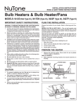
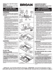
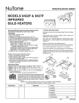
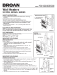
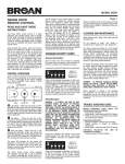
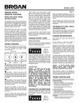
INSTALLATION INSTRUCTIONS
READ & SAVE THESE INSTRUCTIONS!
Bulb Heaters & Bulb Heater/Fans
MODELS: 9412D (Not Type IC), 9417DN (Type IC), 9422P (Type IC), 9427P (Type IC)
IMPORTANT INSTRUCTIONS
PLANNING
READ ALL INSTRUCTIONS BEFORE INSTALLING OR USING THIS HEATER.
Choose the location for your heater. Refer to IMPORTANT INSTRUCTIONS.
MODELS 9417DN & 9427P ONLY – The unit will operate most
efficiently when located where the shortest possible duct run and
minimum number of elbows will be needed. Units are designed
for use with standard 4” round duct.
Note that two-bulb units (9422P & 9427P) can be fitted with one
infrared bulb (for heat) and one reflector bulb (for light). Dual or
multi-controls can be used for separate control of bulbs and/or
exhaust fan. Purchase controls separately.
Refer to FIGURE 1
Follow these basic steps when installing this unit:
1. Nail unit to joists.
2. Attach ductwork (Models 9417DN or 9427P only).
3. Connect power cable.
4. Fasten grille to housing.
To reduce the risk of fire, electric shock, or injury to persons, observe
the following:
1. Use this unit only in the manner intended by the manufacturer. If
you have questions, contact the manufacturer at the address or
telephone number listed in the warranty.
2. Before servicing or cleaning unit, switch power off at service panel
and lock the service disconnecting means to prevent power from
being switched on accidentally. When the service disconnecting
means cannot be locked, securely fasten a prominent warning
device, such as a tag, to the service panel.
3. Installation work and electrical wiring must be done by a qualified
person(s) in accordance with all applicable codes and standards,
including fire-rated construction codes and standards.
4. When cutting or drilling into wall or ceiling, do not damage electrical wiring and other hidden utilities.
5. This heater is hot when in use. To avoid burns, do not let bare
skin touch hot surfaces. Keep combustible materials, such as furniture, pillows, bedding, papers, clothes, etc. and curtains at least
3 feet (0.9 m) from the front of the heater.
6. Extreme caution is necessary when any heater is used by or near
children or invalids and whenever the heater is left operating and
unattended.
7. Do not operate any heater after it malfunctions. Disconnect power
at service panel and have heater inspected by a reputable electrician before reusing.
8. Do not use outdoors.
9. To disconnect heater, turn controls to off, and turn off power to
heater circuit at main disconnect panel (or operate internal disconnect switch, if provided).
10.Do not insert or allow foreign objects to enter any ventilation or
exhaust opening, as this may cause an electric shock or fire, or
damage the heater.
11.To prevent a possible fire, do not block air intakes or exhaust in
any manner.
12.A heater has hot and arcing or sparking parts inside. Do not use it
in areas where gasoline, paint, or flammable vapors or liquids are
used or stored.
13.Use this heater only as described in this manual. Any other use
not recommended by the manufacturer may cause fire, electric
shock, or injury to persons.
14. This product must be grounded.
15.Do not install heater in a tub or shower enclosure.
16.This product is designed for installation in flat ceilings only. DO
NOT MOUNT THIS PRODUCT IN A WALL.
17. Install heater in flat ceiling only - at least 6 inches from any wall.
18.Do not connect heater to dimmer switch or speed control.
DAMPER/DUCT
CONNECTOR
POWER CABLE
HOUSING
MOUNTING
BRACKET
CEILING
JOIST
CEILING MATERIAL
SAVE THESE INSTRUCTIONS
1
BULB(S)
GRILLE
FIGURE 1
PREPARATION
1. Remove the unit from carton. Save carton for use as plaster
shield in rough-in installations.
Refer to FIGURE 2
2. Slide adjustable mounting brackets into bracket channels on
housing.
FIGURE 2
2
INSTALLATION
WARNING: To reduce the risk of fire, do not store or use
gasoline or other flammable vapors and liquids in the vicinity
of the heater.
CAUTION: High temperature, risk of fire, keep electrical cords,
drapery, furnishings, and other combustibles at least 3 feet (0.9
m) from the front of the heater and away from the side and rear.
Refer to FIGURE 3
1. Position unit between joists and extend mounting brackets.
2. Nail brackets firmly to joists. Bottom of brackets should be positioned flush with joist bottom.
Refer to FIGURE 4
3. Brackets are factory-set for ½” thick ceiling material. For thicker
ceilings, loosen 4 vertical adjusting screws and lower housing
to appropriate thickness on gauges. Tighten vertical adjusting
screws firmly.
FIGURE 3
DAMPER/DUCT
CONNECTOR
ATTACH DUCTWORK
(MODELS 9417DN & 9427P ONLY)
Refer to FIGURE 4
1. Snap the damper/duct connector onto housing. Make sure that
tabs on the connector lock in housing slots and that gravity
closes damper.
2. Attach 4” round duct to damper/duct connector and run ductwork
to the outside through a roof or wall cap. Check damper to make
sure it opens freely. Tape all joints to make them secure and air
tight.
VERTICAL ADJUSTING
SCREWS
FIGURE 4
3
WIRE THE HEATER
4” ROUND
DUCT
Refer to FIGURE 5
1. Remove wiring box from side of housing. Remove knockout(s)
and connect power cable(s) to wiring box using proper U.L. approved connector.
Refer to FIGURE 6 (on page 3)
2. Wire unit as indicated in appropriate diagram. Push all wiring
into wiring box and replace wiring box onto housing.
FINAL ASSEMBLY
WIRING BOX
Refer to FIGURE 7
1. Protect motor, bulb sockets and wiring from construction dust,
drywall spray, paint, etc. by using the plaster shield. Cut it from
the carton and follow directions printed on it.
2. Finish all ceiling work as necessary.
3. Remove plaster shield and check if bottom of housing is flush
with finished ceiling. If not, loosen vertical adjusting screws,
reposition housing, and retighten screws.
Refer to FIGURE 8
4. Attach grille by hooking springs onto clips on side of housing.
5. Install BR40 or R40-size 250W infrared bulb(s). Center grille
around bulb(s).
FIGURE 5
FIGURE 7
FIGURE 8
4
OPERATION
Before using heater, make sure heater has been properly installed
according to installation steps beginning with the "PLANNING"
section on page 1.
MODELS 9417DN & 9427P OPERATION NOTE: These units are
designed with a thermostat which senses excess heat and may start
the blower automatically. This is normal and is no cause for concern.
5
MAINTENANCE
The following maintenance and cleaning tasks can be performed
by the user. All other servicing must be performed by an authorized
technician If you have any questions, please consult with our customer service department at: 800-558-1711.
LUBRICATION
The heater is permanently lubricated and never needs oiling or
disassembly.
CLEANING
Clean heater once a month as follows:
1. Turn off power at service panel.
2. Make sure bulbs are cool.
3. Use a soft brush attachment to gently vacuum grille openings or
wipe grille clean with a soft cloth.
4. Restore power.
CAUTION: METAL AND ELECTRICAL PARTS SHOULD NEVER
BE IMMERSED IN WATER.
WHITE to
WHITE / GRAY
WHITE to WHITE
WHITE to
WHITE / GRAY
RED TO RED
BLACK to
RED & BLUE
BLACK to
BLACK
GROUND
GROUND
WHITE to
WHITE
BLACK
WHITE
to WHITE
GROUND
GROUND
SWITCH OR TIMER
GROUND
BLACK
BLACK
BLACK
DUAL CONTROL
120 VAC LINE IN
120 VAC LINE IN
120 VAC LINE IN
MODEL 9417DN
Lamp & Vent operate together
WHITE to
WHITE / GRAY
RED to RED
GROUND
BLACK
VENT
MODEL 9412D
WHITE to
WHITE
RED
HEAT
BLACK
SWITCH OR TIMER
BLACK TO BLUE
WHITE to
WHITE / GRAY
MODEL 9417DN
Lamp & Vent operate separately
BLACK to BLACK,
& YELLOW
3 WHITE / GRAY WIRES
BLACK to
BLACK
& RED
RED to RED
& BLUE
BLACK to BLACK
GROUND
GROUND
WHITE to
WHITE
BLACK
WHITE to
WHITE
WHITE to
WHITE
GROUND
BLACK
LIGHT
LIGHT
SWITCH OR TIMER
BLACK
GROUND
HEAT
BLACK
GROUND
RED
BLACK
DUAL CONTROL
RED
VENT & HEAT
120 VAC LINE IN
120 VAC LINE IN
MODEL 9422P
Lamps operate together
120 VAC LINE IN
MODEL 9422P
Lamps operate separately
MODEL 9427P
Vent & Heat operate together –
Light separately
RED to RED
BLACK to
BLACK, & BLUE
BLACK to
BLUE
GROUND
DUAL CONTROL
WHITE to WHITE
BLACK to BLACK
RED to BLUE
BLACK to YELLOW
3 WHITE / GRAY WIRES
RED to RED,
BLACK &
YELLOW
3 WHITE / GRAY WIRES
RED to RED
& YELLOW
WHITE to WHITE / GRAY
WHITE to
WHITE
GROUND
WHITE to
WHITE
GROUND
3 WHITE
WIRES
GROUND
BLACK
LIGHT
& VENT
VENT
BLACK
LIGHT
BLACK
HEAT & LIGHT
HEAT
VENT
HEAT
GROUND
DUAL CONTROL
GROUND
DUAL CONTROL
120 VAC LINE IN
120 VAC LINE IN
MODEL 9427P
Lamps operate together –
Vent separately
MODEL 9427P
Light & Vent operate together –
Heat separately
7
GROUND
RED
RED
RED
3-FUNCTION CONTROL
3 BLACK WIRES
120 VAC LINE IN
MODEL 9427P
Light, Vent & Heat operate separately
FIGURE 6
PARTS LIST
REF.
9412D-R019417DN-R019422P-R01 9427P-R01
PART NO.
PART NO.
PART NO.
PART NO.
DESCRIPTION
1
97010319
97010319
97010320
97010320 Grille Assembly (Includes Ref. No. 2)
2
06170-00
06170-00
06170-00
06170-00 Grille Spring (2 Req.)
3
- - - -
97010254
97009724
97010254 Motor
4
- - - -
98007352
98007426
98007352 Motor Mounting Bracket
5 99770034997700349977003499770034
Bulb Holder
6
- - - -
- - - -
99770037
99770037 Bulb Holder
7
- - - -
99260423
99260423
99260423 Nut, #8-32 (2 Req.)*
8
- - - -
99160360
99160360
99160360 Screw, #8-32 x 1/2 (2 Req.)*
9
99150545
99150545
99150545
99150545 Sheet Metal Screw #8-18 x 3/8 (5 Req.) (7 Req. – 9412D-R01)*
10
99150546
99150546
99150546
99150546 Ground Screw #8-18 x 3/8
11
- - - -
97010255
- - - -
97010255 Blower Wheel
12
- - - -
- - - -
97009762
- - - -
Fan Blade
13
97009475
97009476
97009477
97009478 Housing (Includes Ref. Nos. 9 & 23)
14
- - - -
97009595
- - - -
97009595 Damper/Duct Connector
15
25067-00
20050-09
20050-09
20050-09 Wiring Box Cover
16
99400026
99400026
99400026
99400026 Bushing (2 Req. – 9422P-R01 & 9427P-R01)
17 99270830992708309927083099270830
Wire Clip
19
- - - -
99270835
99270835
99270835 Receptacle
20
- - - -
99270832
- - - -
99270832 Thermostat (Fan)
21
98003036
98003036
98003036
98003036 Mounting Bracket (4 Req.)
22
98007763
98007763
98007763
98007763 Bracket Channel (2 Req.)
23 25064-0025064-0025064-0025064-00
Wiring Box
24
99150564
99150564
99150564
99150564 Screw, #8-18 x ½*
25
- - - -
79270237
79270237
79270237 Thermostat (Lamps)
**
- - - -
- - - -
99270668
99270668 Crimp Connector (2 Req. – 9422P-R01) (3 Req. – 9427P-R01)
MODELS 9412D-R01 & 9417DN-R01
MODELS 9422P-R01 & 9427P-R01
17
17
25
25
3
WARRANTY
MODEL 9422P-R01 ONLY
BROAN-NUTONE ONE YEAR LIMITED WARRANTY
Broan-NuTone warrants to the original consumer purchaser of its products that such products will be free from defects in materials or workmanship for a period of one year from the date of original
purchase. THERE ARE NO OTHER WARRANTIES, EXPRESS OR IMPLIED, INCLUDING, BUT NOT LIMITED TO, IMPLIED WARRANTIES OF MERCHANTABILITY OR FITNESS FOR A PARTICULAR
PURPOSE.
During this one-year period, Broan-NuTone will, at its option, repair or replace, without charge, any product or part which is found to be defective under normal use and service.
THIS WARRANTY DOES NOT EXTEND TO FLUORESCENT LAMP STARTERS, TUBES, HALOGEN AND INCANDESCENT BULBS, FUSES, FILTERS, DUCTS, ROOF CAPS, WALL CAPS AND OTHER ACCESSORIES FOR DUCTING. This warranty does not cover (a) normal maintenance and service or (b) any products or parts which have been subject to misuse, negligence, accident, improper maintenance
or repair (other than by Broan-NuTone), faulty installation or installation contrary to recommended installation instructions.
The duration of any implied warranty is limited to the one-year period as specified for the express warranty. Some states do not allow limitation on how long an implied warranty lasts, so the above
limitation may not apply to you.
BROAN-NUTONE’S OBLIGATION TO REPAIR OR REPLACE, AT BROAN-NUTONE’S OPTION, SHALL BE THE PURCHASER’S SOLE AND EXCLUSIVE REMEDY UNDER THIS WARRANTY. BROANNUTONE SHALL NOT BE LIABLE FOR INCIDENTAL, CONSEQUENTIAL OR SPECIAL DAMAGES ARISING OUT OF OR IN CONNECTION WITH PRODUCT USE OR PERFORMANCE. Some states do not
allow the exclusion or limitation of incidental or consequential damages, so the above limitation or exclusion may not apply to you.
This warranty gives you specific legal rights, and you may also have other rights, which vary from state to state. This warranty supersedes all prior warranties.
To qualify for warranty service, you must (a) notify Broan-NuTone at the address or telephone number below, (b) give the model number and part identification and (c) describe the nature of any defect
in the product or part. At the time of requesting warranty service, you must present evidence of the original purchase date.
Broan-NuTone LLC, 926 W. State Street, Hartford, Wisconsin 53027 www.nutone.com 888-336-3948
8
99045029A
INSTRUCCIONES de INSTALACIÓN
LEA Y CONSERVE ESTAS INSTRUCCIONES!
Calentador de Bombilla y
Calentador de Bombilla/Ventiladores
MODELOS: 9412D (No el Tipo IC), 9417DN (Tipo IC), 9422P (Tipo IC), 9427P (Tipo IC)
INSTRUCCIONES IMPORTANTES
PLANIFICACION
LEA TODAS LAS INSTRUCCIONES ANTES DE INSTALAR O USAR ESTE
CALENTADOR.
Escoja un lugar para su calentador. Lea las instrucciones de “INSTRUCCIONS IMPORTANTE” que aparecen arriba.
MODELOS 9417DN & 9427P SOLAMENTE – La unidad funcionará en forma más
eficiente si se ubica en un lugar donde se minimice el tendido de conductos y el
número de codos. Las unidades han sido diseñadas para uso con conducto redondo
estándar de 10 cm.
Note que las unidades de dos bombillas (9422P & 9427P) pueden montarse con una
bombilla infrarroja (para la calefacción) y una bombilla reflectora (para la luz). Se
pueden usar controles dobles o múltiples para un control separado de las bombillas
y/o ventilador extractor de aire. Los controles se compran por separado.
Refiera a la FIGURA 1
Al instalar esta unidad, siga los siguientes pasos básicos:
1. Clave la unidad a las vigas.
2. Fije los conductos (modelos 9417DN o 9427P solamente).
3. Conecte el cable de potencia.
4. Fije la rejilla a la caja.
Para reducir el riesgo de incendios, descargas eléctricas o lesiones personales, observe
las siguientes precauciones:
1. Use la unidad solo de la manera indicada por el fabricante. Si tiene preguntas,
comuníquese con el fabricante a la dirección o al número telefónico que se incluye
en la garantía.
2. Antes de dar servicio a la unidad o de limpiarla, interrumpa el suministro eléctrico
en el panel de servicio y bloquee los medios de desconexión del servicio para evitar
que la electricidad se reanude accidentalmente. Cuando no sea posible bloquear
los medios de desconexión del servicio, fije firmemente una señal de advertencia
(como una etiqueta) en un lugar visible del panel de servicio.
3. El trabajo de instalación y el cableado eléctrico deben estar a cargo de personal
capacitado, de acuerdo con todos los códigos y normas correspondientes,
incluidos los códigos y normas de construcción específicos sobre protección
contra incendios.
4. Al cortar o perforar a través de la pared o del cielo raso, tenga cuidado de no dañar
el cableado eléctrico ni otros servicios ocultos.
5. Este calentador se calienta cuando se usa. Para evitar quemaduras, no deje que la
piel desnuda toque las superficies calientes. Mantenga materiales combustibles
como muebles, almohadas, ropa de cama, papeles, ropa, etc., así como las
cortinas, por lo menos a 3 pies (0.9 m) de la parte delantera del calentador.
6. Es necesario tener extremo cuidado cuando se use un calentador cerca de niños o
personas inválidas, y siempre que el calentador se deje funcionando y sin atención.
7. No haga funcionar ningún calentador después de que presente una falla.
Desconecte la energía eléctrica en el panel de servicio y pida que un electricista
acreditado inspeccione el calentador antes de volverlo a usar.
8. No lo use en exteriores.
9. Para desconectar el calentador, mueva los controles a la posición de apagado y
desconecte la energía eléctrica al circuito del calentador en el panel de desconexión
principal (o active el interruptor de desconexión interna, si existe).
10.No inserte ni permita que objetos extraños entren en la abertura de ventilación
o de escape, pues esto puede ocasionar una descarga eléctrica, un incendio o
daños al calentador.
11. Para prevenir un posible incendio, no bloquee la entrada o salida del aire de ninguna
manera.
12. El calentador tiene piezas calientes y que pueden generar arcos eléctricos o chispas
en el interior. No lo use en áreas donde se use o almacene gasolina, pintura o
vapores o líquidos flamables.
13. Use este calentador solamente como se describe en este manual. Cualquier otro
uso no recomendado por el fabricante puede ocasionar un incendio, una descarga
eléctrica o lesiones a personas.
14. Este producto debe ser conectado a tierra.
15. No instale esta unidad sobre una bañera o ducha.
16. Este producto se diseña para la instalación en techos hasta una echada de 12/12.
Conector de conductor debe señalar hacia arriba. NO MONTE ESTE PRODUCTO
EN UNA TECHO.
17.Instálelo únicamente en techos, a distancias mínimas de 6 pulg. (15 cm) de
cualquier pared.
18. No conecte el calentador a un variador de luz o control de velocidad.
AMORTIGUADOR/ACOPLE DE
CONDUCTO
CABLE DE POTENCIA
CASA
SOPORTE DE
MONTAJE
VIGA DEL
CIELO
RASO
MATERIAL DEL
CIELO RASO
GUARDE ESTAS INSTRUCCIONES
9
BOMBILLA
REJILLA
FIGURA 1
PREPARACION
1. Saque la unidad de la caja de cartón. Guarde la caja de cartón para su uso como
escudo de yeso al principio de una instalación.
Refiera a la FIGURA 2
2. Meta los soportes de montaje ajustables en los canales de soporte en la caja.
FIGURA 2
10
INSTALACION
ADVERTENCIA: Para reducir el riesgo de incendio, no almacene ni use gasolina u
otros vapores y líquidos flamables en las cercanías del calentador.
PRECAUCIÓN: Temperatura alta, el riesgo de incendio, mantenga los cables
eléctricos, cortinas, muebles y otros materiales combustibles por lo menos 3 pies
(0,9 m) del frente del calentador y lejos de la cara y la parte trasera.
Refiera a la FIGURA 3
1. Coloque la unidad entre las vigas y extienda los soportes de montaje.
2. Clave firmemente los soportes en las vigas. Las partes de abajo de los soportes
deben colocarse a nivel con la parte de abajo de la viga.
Refiera a la FIGURA 4
3. Los soportes se fijan en fábrica para material de cielo raso de un grosor de 1,3
cm. Para cielo raso más gruesos, afloje 4 tornillos de ajuste vertical y baje la caja
al grosor apropiado según los calibradores. Atornille firmemente los tornillos de
ajuste vertical.
FIGURA 3
ACOPLE DE
AMORTIGUADOR/
CONDUCTO
FIJE LOS CONDUCTOS
(MODELOS 9417DN & 9427P SOLAMENTE)
Refiera a la FIGURA 4
1. Enganche el acople de amortiguador/conducto en la caja. Compruebe que las
orejetas en el acople se enganchen en las ranuras de la caja y que el amortiguador
cierre por gravedad.
2. Fije el conducto redondo de 10 cm al acople del amortiguador/conducto y saque
el tendido de los conductos al exterior a través de una cubierta de cielo raso o
pared. Verifique que el amortiguador se abra libremente. Ponga cinta alrededor
de todas las uniones para que queden seguras y herméticas.
TORNILLOS DE
AJUSTE VERTICAL
FIGURA 4
CABLEADO DEL CALENTADOR
CONDUCTO
REDONDO
DE 10 cm
El trabajo de instalación y el cableado eléctrico deben estar a cargo de personal
capacitado, de acuerdo con todos los códigos y normas correspondientes, incluidos los códigos y normas de construcción específicos sobre protección contra
incendios.
Refiera a la FIGURA 5
1. Quite la caja de conexiones del costado de la caja. Saque un disco(s) removible y
conecte cable(s) de potencia a la caja de conexiones usando el conector correcto
aprobado por U.L.
Refiera a la FIGURA 6 (en página 7)
2. Haga el cableado de la unidad tal como se indica en el diagrama correspondiente.
Ponga todas las conexiones en la caja de conexiones y vuelva a colocar ésta en
su lugar.
CAJA DE CONEXIONES
FIGURA 5
ENSAMBLADO FINAL
Refiera a la FIGURA 7
1. Proteja el motor, enchufe de la bombilla y cableado contra el polvo de la construcción, rocíos de yeso, pintura, etc., usando el escudo de yeso. Córtelo de la caja
de cartón y siga las instrucciones que aparecen impresas en la misma.
2. Termine el trabajo de cielo raso ségun se necesite.
3. Quite el escudo de yeso y verifique si la parte inferior de la caja está a nivel con el
cielo raso terminado. De lo contrario, afloje los tornillos de ajuste vertical, cambie
la posición de la caja y vuelva a apretar los tornillos.
Refiera a la FIGURA 8
4. Fije la rejilla enganchando los resortes a los sujetadores al costado de la caja.
5. Instale bombilla(s) infrarrojas 250W de tamaño BR40 o R40. Centre la rejilla
alrededor de la(s) bombilla(s).
FIGURA 7
FIGURA 8
12
OPERACIÓN
Antes de usar el calentador, asegúrese de que esté instalado adecuadamente, de
acuerdo con los pasos de instalación indicados en “PLANIFICACION” en la página 5.
INSTRUCCIONES SOBRE EL FUNCIONAMIENTO DEL MODELOS 9417DN y 9427P:
Estas unidads ha sido diseñada con un termostato que detecta los excesos de calor y
puede encender el soplador automáticamente. Esto es normal y no debe ser motivo
de preocupación.
13
MANTENIMIENTO
El usuario puede realizar las siguientes tareas de mantenimiento y limpieza. Todos los
demás servicios los debe realizar un técnico autorizado. Si tiene preguntas, consulte a
nuestro departamento de servicio al cliente llamando al: 800-558- 1711.
LUBRICACIÓN
El calentador está permanentemente lubricado y nunca necesitará ponerle aceite ni
desarmarlo.
LIMPIEZA
Limpie el calentador una vez al mes tal como sigue:
1. Apague la energía eléctrica en el panel de servicio.
2. Asegúrese de que el elemento de calefacción esté frío.
3. Use un aditamento de cepillo suave para aspirar suavemente aberturas de la rejilla
o limpie la rejilla con un paño suave.
4. Restaure la energía eléctrica.
CUIDADO: LAS PIEZAS METALICAS Y ELECTRICAS NUNCA SE DEBEN SUMERGIR
EN AGUA.
14
BLANCO a
BLANCO / GRIS
BLANCO a BLANCO
ROJO A ROJO
BLANCO a
BLANCO / GRIS
NEGRO a
ROJO y AZUL
NEGRO a
NEGRO
TIERRA
TIERRA
BLANCO a
BLANCO
NEGRO
NEGRO
CONMUTADOR O
TEMPORIZADOR
TIERRA
NEGRO A AZUL
BLANCO
to BLANCO
TIERRA
ROJO
CALIFACCION
INTERRUPTOR O
TEMPORIZADOR
TIERRA
TIERRA
NEGRO
EXTRACCION
NEGRO
NEGRO
LINEA DE ENTRADA 120 VCA
NEGRO
CONTROL DE DOS
FUNCCIONES
LINEA DE ENTRADA 120 VCA
MODELO 9412D
LINEA DE ENTRADA 120 VCA
MODELO 9417DN
La lámpara y el ventilador
funcionan a la vez
ROJO a ROJO
BLANCO a
BLANCO / GRIS
BLANCO a
BLANCO
MODELO 9417DN
La lámpara y el ventilador
funcionan por separado
BLANCO a
BLANCO / GRIS
NEGRO a
NEGRO
y ROJO
NEGRO a
NEGRO
y AMARILLO
3 ALAMBRES
BLANCO / GRIS
ROJO a ROJO
y AZUL
TIERRA
NEGRO a NEGRO
BLANCO a
BLANCO
TIERRA
BLANCO a
BLANCO
BLANCO a
BLANCO
TIERRA
NEGRO
NEGRO
LUZ
LUZ
NEGRO
INTERRUPTOR O
TEMPORIZADOR
TIERRA
ROJO
CALIFACCION
NEGRO
TIERRA
CONTROL DE DOS
FUNCCIONES
LINEA DE ENTRADA 120 VCA
ROJO
VENTILADOR y
CALEFACCION
NEGRO
TIERRA
CONTROLE DE 2 FUNCCIONES
LINEA DE ENTRADA 120 VCA
LINEA DE ENTRADA 120 VCA
MODELO 9422P
Las lámparas funcionan a la vez
MODELO 9422P
Las lámparas funcionan por separado
NEGRO a
AZUL
NEGRO a
NEGRO y AZUL
MODELO 9427P
El ventilador y calentador funcionan
a la vez – la luz por separado
ROJO a ROJO
BLANCO a BLANCO
NEGRO a NEGRO
ROJO a AZUL
3 ALAMBRES
BLANCO / GRIS
ROJO a ROJO,
NEGRO y
AMARILLO
3 ALAMBRES
BLANCO / GRIS
ROJO a ROJO
y AMARILLO
BLANCO a BLANCO / GRIS
BLANCO a
BLANCO
TIERRA
BLANCO a
BLANCO
TIERRA
NEGRO
3 ALAMBRES
BLANCOS
TIERRA
NEGRO
LUZ
LUZ y
EXTRACCION
VENTILADOR
NEGRO a AMARILLO
CALEFACCION
NEGRO
TIERRA
ROJO
CALEFACCION
y LUZ
ROJO
CONTROLE DE 2 FUNCCIONES
ROJO
EXTRACCION
CALEFACCION
TIERRA
CONTROLE DE 2 FUNCCIONES
LINEA DE ENTRADA 120 VCA
MODELO 9427P
Las lámparas funcionan a la vez –
El ventilador por separado
TIERRA
LINEA DE ENTRADA 120 VCA
MODELO 9427P
La luz y el ventilador funcionan a la vez
– calentador por separado
15
CONTROLE DE
3 FUNCCIONES
3 ALAMBRES NEGROS
LINEA DE ENTRADA 120 VCA
MODELO 9427P
La luz, ventilador y calentador
funcionan por separado
FIGURA 6
LISTA DE PIEZAS
9412D-R019417DN-R019422P-R01 9427P-R01
REF. NO. DE PIEZAS NO. DE PIEZAS NO. DE PIEZAS NO. DE PIEZASDESCRIPCION
1
97010319
97010319
97010320
97010320 Equipo de la rejilla (incluye No. 2)
2
06170-00
06170-00
06170-00
06170-00 Resorte de la rejilla (se requieren 2)
3
- - - -
97010254
97009724
97010254 Motor
4
- - - -
98007352
98007426
98007352 Soporte del montaje del motor
5 99770034997700349977003499770034
Portabombilla
6
- - - -
- - - -
99770037
99770037 Portabombilla
7
- - - -
99260423
99260423
99260423 Tuerca, #8-32 (se requieren 2)
8
- - - -
99160360
99160360
99160360 Tornillo, #8-32 x 1/2 (se requieren 2)
9
99150545
99150545
99150545
99150545 Tornillo de chapa metálica #8-18x3/8 (se req. 5) (se req. 7 - 9412D-R01)
10
99150546
99150546
99150546
99150546 Tornillo de tierra #8-18x3/8
11
- - - -
97010255
- - - -
97010255 Rueda del soplador
12
- - - -
- - - -
97009762
- - - -
Paleta del ventilador
13
97009475
97009476
97009477
97009478 Casa (incluye No. 9 y 23)
14
- - - -
97009595
- - - -
97009595 Conector de amortiguador/conducto
15
25067-00
20050-09
20050-09
20050-09 Cubierta de caja de conexiones
16
99400026
99400026
99400026
99400026 Manguito aislador (se req. 2 – 9422P-R01 y 9427P-R01)
17 99270830992708309927083099270830
Sujetador de alambre
19
- - - -
99270835
99270835
99270835 Enchufe
20
- - - -
99270832
- - - -
99270832 Termostato (Ventilador)
21
98003036
98003036
98003036
98003036 Soporte de montaje (se requieren 4)
22
98007763
98007763
98007763
98007763 Canal de soporte (se requieren 2)
23 25064-0025064-0025064-0025064-00
Caja de conexiones
24
99150564
99150564
99150564
99150564 Tornillo, #8-18 x ½
25
- - - -
79270237
79270237
79270237 Termostato (Focos)
**
- - - -
- - - -
99270668
99270668 Conector de pliegue (se req. 2 – 9422P-R01) (se req. 3 – 9427P-R01)
MODELOS 9412D-R01 y 9417DN-R01
MODELOS 9422P-R01 y 9427P-R01
17
17
25
25
3
GARANTIA
MODELO 9422P-R01 SOLOMENTE
GARANTÍA BROAN-NUTONE LIMITADA POR UN AÑO
Broan-NuTone garantiza al consumidor comprador original de sus productos que dichos productos carecerán de defectos en materiales o en mano de obra por un período de un año a partir de la fecha original
de compra. NO EXISTEN OTRAS GARANTÍAS, EXPLICITAS O IMPLÍCITAS, INCLUYENDO, ENTRE OTRAS, GARANTÍAS IMPLÍCITAS DE COMERCIALIZACIÓN O APTITUD PARA UN PROPÓSITO PARTICULAR.
Durante el período de un año, y a su propio criterio, Broan-NuTone reparará o reemplazará, sin costo alguno, cualquier producto o pieza que se encuentre defectuosa bajo condiciones normales de servicio y
uso.
LA PRESENTE GARANTÍA NO CUBRE LOS TUBOS FLUORESCENTES NI SUS ARRANCADORES, BOMBILLAS DE HALÓGENO E INCANDESCENTES, FUSIBLES, FILTROS, CONDUCTOS, TAPONES DE TECHO
O PAREDES Y DEMÁS ACCESORIOS PARA CONDUCTOS. Esta garantía no cubre (a) mantenimiento y servicio normales o (b) cualesquiera productos o piezas que hayan sido utilizados de forma errónea,
negligente, que hayan causado un accidente, o que hayan sido reparados o mantenidos inapropiadamente (por otras compañías que no sean Broan-NuTone), instalación defectuosa, o instalación contraria a
las instrucciones de instalación recomendadas.
La duración de cualquier garantía implícita se limita a un período de un año como se especifica en la garantía expresa. Algunos estados no permiten limitaciones en cuanto al tiempo de vencimiento de una
garantía implícita, por lo que la limitación antes mencionada puede no aplicarse a usted.
LA OBLIGACIÓN DE BROAN-NUTONE DE REPARAR O REEMPLAZAR, SIGUIENDO EL CRITERIO DE BROAN-NUTONE, DEBERÁ SER EL ÚNICO Y EXCLUSIVO RECURSO LEGAL DEL COMPRADOR BAJO
ESTA GARANTÍA. BROAN-NUTONE NO SERÁ RESPONSABLE POR DAÑOS INCIDENTALES, CONSECUENTES, O POR DAÑOS ESPECIALES QUE SURJAN A RAÍZ DEL USO O DESEMPEÑO DEL PRODUCTO.
Algunos estados no permiten la exclusión o limitación de daños incidentales o consecuentes, por lo que la limitación antes mencionada puede no aplicarse a usted.
Esta garantía le proporciona derechos legales específicos, y usted puede también tener otros derechos, los cuales varían de estado a estado. Esta garantía reemplaza todas las garantías anteriores.
Para calificar para la garantía de servicio, usted debe (a) notificar a Broan-NuTone al domicilio o al número de teléfono que se menciona abajo, (b) dar el número del modelo y la identificación de la pieza, y
(c) describir la naturaleza de cualquier defecto en el producto o la pieza. En el momento de solicitar servicio cubierto por la garantía, usted debe de presentar un comprobante con la fecha original de compra.
Broan-NuTone LLC, 926 W. State Street, Hartford, Wisconsin 53027 www.nutone.com 888-336-3948
16
99045029A