1
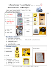
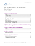
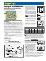
Safety+PLUS ADVANTAGE
®
COATED STAINLESS STEEL GAS CONNECTORS
INSTALLATION INSTRUCTIONS
For Residential
and Commercial
Gas Appliances
DO NOT INSTALL THIS PRODUCT UNTIL YOU HAVE READ AND UNDERSTAND
ALL INSTRUCTIONS!
The Safety+PLUS ADVANTAGE™ coated stainless steel gas connector combines two
state-of-the-art technologies to deliver a superior gas connector for your home and
family. Safety+PLUS ADVANTAGE gas connectors feature an advanced corrosion
resistant coating called ProCoat®. A proprietary polymer coating, ProCoat is specially
engineered to resist the corrosion from harsh chemicals found in household cleaning,
plumbing repair and masonry products. Approved for indoor and outdoor use, ProCoat
is formulated to resist the harsh effect of UV rays and salt.
Safety+PLUS® excess flow valves (EFV), an automatic safety valve for gas, utilize a
patented magnet-based excess flow technology. In the event of a gas line rupture or
disconnection at the appliance, the Safety+PLUS valve immediately restricts gas flow to
a non-hazardous level (a bypass flow) to avert the potential for a dangerous release of
gas into the home. Only after the gas line has been properly repaired, the bypass flow
automatically resets the valve, allowing gas flow to resume to the appliance.
• Use only on low pressure natural and LP gas piping systems. DO NOT USE on
pipelines or piping systems that transfer or move liquids, including high-pressure liquid propane.
• Use only with gas line pressures at a minimum of 4” water column (W.C.) and not greater than 14” W.C. (1/2 psig) at the stub out.
• Use only in connection with residential and commercial gas appliances, where installation is immediately downstream of the gas supply stub out and manual gas shut-off valve.
Tools Needed for Installation: • (2) 10" adjustable wrenches
• Pipe dope or gas pipe thread tape
• Leak detection solution
2. Identify the maximum (gas) input rating of the
appliance (refered to as “input rating”).
Manufacturer’s label, located near the gas inlet
of the appliance will contain this information.
(See Fig. B) Contact the appliance manufacturer
if you are unsure of the correct rating for the
appliance.
3. Using Chart 1, select the gas connector with the maximum flow capacity that is HIGHER than the input rating of the appliance. However, select the gas connector with the maximum flow capacity that is CLOSEST TO the input rating of the
appliance. (Figure C)
WARNING: The maximum gas input rating of the
appliance must be within the flow capacity range of the connector. If the Safety+PLUS gas
connector is not properly sized to the application, the Safety+PLUS connector may not activate in
the event of a gas line rupture or disconnection.
If the Safety+PLUS gas connector is under sized
for the appliance, may activate prematurely
restricting gas flow during normal operation of
the appliance.
Fig. B
CONNECTOR
CONNECTOR
CAPACITY
CONNECTOR
CAPACITY
CAPACITY
36”
36”
36”
33,400
33,400
33,400
71,100
63,000
63,000
63,000
125,000
125,000
125,000
GAS APPLIANCE
GAS
APPLIANCE
INPUT
RATING
GAS
APPLIANCE
INPUTRATING
RATING
INPUT
62,500
62,500
62,500
Fig. C
4. Finally, select the connector with the end fittings that match the outlet of your manual gas shut-off valve and the gas inlet to the appliance. (Figure D)
Fig. D
Chart 1
Gas Connector Maximum Flow Capacity
Part #
EFV Closing
Flow Rate
ID
Color
Code
12”
18”
24”
30”
36”
48”
60”
72”
CSSL 95,000 Btu/Hr 1/4
Purple
48,000
43,800
40,000
36,400
33,400
28,300
24,900
23,100
CSSD 95,000 Btu/Hr 3/8
Green
75,000
70,000
70,000
63,000
65,000
60,500
53,200
49,100
CSSC 195,000 Btu/Hr 1/2
Gold
135,000 130,000 130,000 125,000 125,000 106,000 93,200
86,000
NOTE: All Safety+PLUS valves require minimum inlet pressure of 4” W.C. and are rated at a maximum inlet pressure of 1/2 psig. (14” W.C.). Flow rates given are for 0.6 specific gravity natural gas with an average heating value of 1000 BTU per cubic foot; therefore, 1,000 BTU/Hr is equal to 1 SCFH (standard cubic foot per hour).Chart to be used in accordance with the local plumbing codes and with reference to IAPMO/ANSI UPC 1-2003; NFPA 54/ANSI Z223.1 - National Fuel Gas Code.
INSTALLATION INSTRUCTIONS
SAFETY PRECAUTIONS:
SIZING THE CONNECTOR TO THE APPLIANCE
1. Measure the distance between the gas supply stub out and the appliance.
Add 2 – 3 inches to the measured distance for appropriate connector length for the installation. (See Fig. A)
1. Read and follow all installation instructions carefully.
When in doubt, call a licensed plumber or your local gas company.
2. DO NOT reuse the gas connector or fittings.
The connector, fittings and valve are designed for use on original installation only. Removal of
connector and additional handling may have
damaged connector making it unsafe for reuse.
3. DO NOT use this gas connector on appliances equipped with rollers or casters. (Figure E)
This connector is designed for limited movement after installation. Repeated bending, flexing or extreme vibration can cause metal fatigue. DO NOT repeatedly move appliance for cleaning once installed.
Fig. E
Fig. F
4. AVOID connector contact with foreign objects such as wall studs, electrical wiring, copper or iron pipe, paneling sheet metal, etc. Gas systems should NOT be used as electrical grounds. Dissimilar metals should be isolated from each other.
Fig. A
5. Keep cleaning solvents containing ammonia or chlorine away from uncoated gas connectors. (Figure F) DO NOT store these solutions in closets containing a water heater or furnace. Chlorine can corrode uncoated stainless steel.
6. DO NOT use connectors to make a direct connec-
tion to L.P. gas containers. (Figure G) Connection MUST be made to the regulator device only.
7. DO NOT use connectors on appliances in moving vehicles such as RV’s, trailers, etc. This does not include manufactured housing (permanent residence mobile homes).
Fig. G
WARNING: DO NOT CONNECT Safety+PLUS EXCESS FLOW VALVE DIRECTLY TO
THE APPLIANCE. The Safety+PLUS valve must be installed between the gas supply pipe and the flexible gas connector. If installed to the gas inlet of the appliance, the Safety+PLUS valve will not operate.
WARNING: DO NOT USE matches, candles, open flames or other sources of ignition during product installation. A spark or flame may ignite gas vapors causing property damage and/or personal injury including death. Extinguish all pilot lights within 50ft. before proceeding with appliance installation.
1. Turn off gas supply at the appliance before discon-
necting old appliance. The manual gas shut-off
valve, located near the appliance, is closed and gas
is shut-off when valve handle is perpendicular to
the valve body (Figure H). In absence of manual gas shut-off valve near appliance location, gas MUST be shut off at main valve, before the meter. Fig. H
NOTE: The Fuel Gas Codes require installation of a manual gas shut-off valve in the same room, within
easy reach of the appliance.
2. Clean ALL pipe threads with a wire brush and rag to ensure connections are free
of any debris such metal shavings, rust, dirt, oil or water.
WARNING: DO NOT USE matches, candles, open flames or other sources of ignition to leak test
connector or fittings. A spark or flame may ignite gas leaks potentially causing property damage
and/or personal injury including death. (Figure M)
Fig. M
CAUTION: DO rinse connector with water and towel dry after leak testing connections. Soap and test solutions may cause an uncoated connector to
corrode.
10. Wait at least 10 minutes to light pilot(s) once you have leak tested all connections and have found no leaks, to be certain that all vapors have dissipated.
WARNING: DO NOT USE motorized equipment or Fig. N
other sources of combustion to dissipate gas vapors. Motorized equipment can ignite gas vapors causing fire or explosion which may result in property damage and/or personal injury including death. (Figure N)
DANGER: Fuel gases are colorless, tasteless and in its pure state, odorless.
They are odorized (rotten egg smell) so that their presence can be detected.
LP gases are heavier than air and dissipate slower than natural or manufactured gases. LP gas, if released in quantity, will accumulate in low-lying areas such
as a basement or crawl space.
THIS SAFETY+PLUS EXCESS FLOW VALVE (included with the connector) IS NOT
DESIGNED TO ACTIVATE IF ANY OF THE FOLLOWING CONDITIONS ARE PRESENT:
3. Apply pipe thread sealant to the male pipe threads.
CAUTION: DO NOT apply pipe thread sealant or tape to flare ends of fittings or valves (Figure I). Sealant and tape will prevent this connection from sealing properly.
• There are small leaks such as pin hole leaks or lesser leaks caused by cracks
or loose connections that do not increase the gas flow above normal operating capacity of the appliance.
4. If not already installed, thread a manual gas shut-off Fig. I
valve onto gas stub out. Using one adjustable wrench to stabilize the gas stub out, wrench tighten valve with second wrench.
5. Inspect the valve before installing to be certain it has not been damaged. Thread brass Safety+PLUS valve to manual gas shut-off valve. Using one adjustable wrench to stabilize the manual gas shut-off valve, wrench tighten Safety+PLUS valve with second wrench. Tighten all connections in the same manner.
6. Thread steel gas fitting to gas inlet on appliance. Wrench tighten.
7. Thread flare nuts of gas connector onto Safety+PLUS valve and steel fitting.
Wrench tighten both connections.
• DO NOT stretch connector to make it fit. Connector should be at least 2 – 3 inches longer than the distance between the appliance and gas supply. Stretching the connector will stress the stainless steel which may cause cracks
or breaks during appliance use or if accidentally hit.
• DO NOT kink, twist or bend connector sharply – doing so will cause the connector to fail. Be careful when installing connector to avoid pinching or kinking the connector (Figure J).
Fig. L
9. Leak test all connections with a clear soap and water solution or leak detection solution; bubbles will indicate a leak in the connection. (Figure L)
If a leak is detected, turn off gas supply before further tightening connections.
INSTALLATION:
WARNING: DO NOT TURN ON APPLIANCE UNTIL ALL CONNECTIONS ARE LEAK TESTED!
Fig. J
• The gas appliance malfunctions or the user fails to shut off gas burners.
• There is foreign matter, such as pipe thread sealant, lodged in the valve.
• The manual gas shut-off valve is partially opened, or there is a pipe break
or damage that has occurred upstream of the Safety+PLUS valve excess flow valve, that prevents sufficient gas flow through the valve.
• There is an insufficient gas flow from an improperly sized gas piping system upstream of the Safety+PLUS valve.
• The gas flow through the valve is in the wrong direction. The excess flow valve responds to gas flow in one direction only (see product label). The valve must be installed so that the arrows point in the direction of gas flow.
• The Safety+PLUS valve is damaged, exposed to fire or improperly installed.
WARNING: Replace the Safety+PLUS valve if it has been damaged or exposed
to fire.
Excess Flow Valve
Gas Connector
• DO NOT allow connector to become trapped against sharp edges or corners.
• DO NOT use connector if bent tighter than
1-1/2 IN. (the diameter of a golf ball). (Figure K)
Fig. K
8. SLOWLY open the manual gas shut-off valve to allow gas to enter the system. The valve is open and gas is flowing when the valve handle isparallel to
the valve body (Figure H). NOTE: If gas enters system too quickly, the Safety+PLUS valve may activate pre-maturely. If this occurs, the Safety+PLUS valve will re-open in less than 60 seconds (you will hear a soft “click”).
©2009, 2011 BrassCraft Mfg.
BrassCraft Mfg. , 39600 Orchard Hill Place Novi, Michigan 48375-5331
TOLL-FREE: 877.272.7755 FAX: 248.305.6011 www.brasscraft.com
325.02 11/11