1
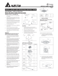
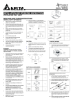
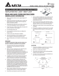
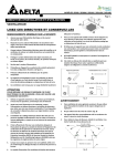
MODEL VFB25AC / VFB25AD/ VFB25ACH / VFB25ADH/ VFB25AEH / VFB25AX INSTALLATION AND OPERATING INSTRUCTIONS CEILING VENTILATION FAN READ AND SAVE THESE INSTRUCTIONS GENERAL SAFETY INFORMATION 1. Make sure that the electric service supply voltage is AC 110~220V, 50~60Hz. 2. Follow all local electrical and safety codes, as well as the Nation Electrical Code (NEC) and the Occupation Safety and Healthy Act (OSHA). 3. Always disconnect the power source before working on or near the ventilating fan, motor or junction box. 4. Protect the power cord from sharp edges, oil, grease, hot surfaces, chemicals or other objects. 5. Do not kink the power cord. 6. Do not install the unit where ducts are configured as shown in Fig. A. 7. Provide suction parts with proper ventilation. 8. This unit is UL listed for use over a bathtub or shower when installed in a GFCI protected branch circuit. 9. These ventilating fans are intended for residential usage only. Turning angle too large Duct shrink Too many elbows Elbow near the body Body Fig. A CAUTION WARNING TO REDUCE THE RISK OF FIRE, ELECTRIC SHOCK, OR INJURY TO PERSONS, OBSERVE THE FOLLOWING: 1. 2. 1. Use this unit only in the manner intended by the manufacturer. If you have any questions, contact the manufacturer. For general ventilating use only. Do not use to exhaust hazardous or explosive materials and vapors. 2. Not for use in cooking area. (Fig. B) 3. This product must be properly grounded. Before servicing or cleaning unit, switch power off at service panel and lock the service disconnecting means to prevent power from being switched on accidentally. When the service disconnecting means cannot be locked, securely fasten a prominent warning device, such as a tag, to the service panel. Cooking area 3. Installation work and electrical wiring must be done by qualified person(s) in accordance with all applicable codes and standards, including fire-rated construction. 4. Sufficient air is needed for proper combustion and exhausting of gases through the flue (chimney) of fuel burning equipment to prevent back drafting. Follow the heating equipment manufacturer’s guideline and safety standards such as those published by the National Fire Protection Association (NFPA), and the American Society for Heating Refrigeration and Air Conditioning Engineers (ASHRAE) and local code authorities. 5. When cutting or drilling into wall or ceiling, do not damage electrical wiring and other hidden utilities. 6. Ducted ventilating fan must always be vented to the outdoors. 7. Do not install this ventilating fan where air temperature may exceed 40°C (104°F). 8. If this unit is to be installed over a tub or shower, it must be marked as appropriate for the application and be connected to a GFCI (Ground Fault Circuit Interrupter) – protected branch circuit. 9. These models are UL listed for tub and shower enclosures. 10. Do not use this unit with any other solid-state control device. Solid-state controls may cause harmonic distortion, which can cause motor humming noise. Grille 1 11. Before servicing or cleaning unit, switch power off at service panel and lock the service disconnecting means to prevent power from being switched on accidentally. When the service disconnecting means cannot be locked, securely fasten a prominent warning device, such as a tag, to the service panel. Long Screw (M4x25) 6 Screw (M4x12) 3 Suspension bracketⅠ 6.1(155) 1 Suspension bracketⅡ 11.8(300) 1 Suspension bracketⅢ 14.0(355) 1 12. NEVER place a switch where it can be reached from a tub or shower. 13. Not to be installed in a ceiling thermally insulated to a value greater than R40. (This is required for installation in Canada only) Fig. B SUPPLIED ACCESSORIES Part name inches(mm) [1] Appearance Quantity MODEL VFB25AC / VFB25AD/ VFB25ACH / VFB25ADH/ VFB25AEH / VFB25AX INSTALLATIONS A.Install with wood frame Model No. Install Dim. (inches) VFB25AEH VFB25ADH VFB25ACH 9.98 ╳ 9.68 9.98 ╳ 9.68 9.98 ╳ 9.68 VFB25AD VFB25AC VFB25AX 9.98 ╳ 9.68 9.98 ╳ 9.68 9.98 ╳ 9.68 1. Body installation 1-1. Construct the wood frame (not provided) with 30mm square bar and attach it to the ceiling joist. 1-2. Attach the duct connector to the wood frame with taping screws. 1-3. Insert the body into the wood frame and connect it to the duct connector. Secure the body on wood frame with taping screws. 2-1. Insert the suspension bracketⅠ into the bracket cover of adaptor side and select one of suspension bracketⅡ and Ⅲ of the back of the fan body. 1-4. Follow step 4 to 7 of installation to complete the installation work. 2-2. Insert the fan between joists. Make sure the fan body is level and perpendicular with the joist. 2-3. Ensure the distance between ceiling and fan body for the thickness of grille. 2-4. Secure the suspension bracket to joists by using screw. 2-5. Secure the suspension bracket to fan body by using screw. 2-6. Follow step 4 to 7 of installation to complete the installation work. 3. B. Install with joist 1. Choose the installation type according to the figure as below: Spacing A on Center Joints 2. Insert Suspension Bracket 12 inches Refer to Fig. C-01, D-01, E-01 16, 19.2 and 24 inches Refer to Fig. C-02, D-02, E-02 TypeⅠ-12 inches between joists [2] TypeⅡ-16, 19.2 and 24 inches between joists MODEL VFB25AC / VFB25AD/ VFB25ACH / VFB25ADH/ VFB25AEH / VFB25AX 5-5. 14 AWG (2.1 mm2) is the smallest conductor that shall be used for branch-circuit wiring. 6. Test run and grille attachment 6-1. When the power on, check for abnormal vibration or sound. 6-2. Insert the mounting springs into the slots and mount the grille to the body. 3-1. Insert the suspension bracketⅠ into the bracket cover of adaptor side and insert the suspension bracketⅡ and Ⅲ into the back of the fan body. 3-2. Insert the fan between joists. Make sure the fan body is level and perpendicular with the joist. 3-3. Ensure the distance between ceiling and fan body for the thickness of grille. 3-4. Secure the suspension bracket to joists by using screw. 3-5. Secure the suspension bracket to fan body by using screw. 3-6. Follow step 4 to 7 of installation to complete the installation work. 4. Duct connection 7. Operation Humidity Models: VFB25ACH, VFB25ADH, VFB25AEH Manual operation for humidity control mode & full speed mode. Power on the fan once and fan is in humidity mode. Fan blades will spin or not spin depending on level of humidity in the environment. 7-1 Humidity sensor mode: 4-1. Insert the duct into the duct connector and tape all ductworks connection to make them secure and air tight. Blue LED indicator lights show humidity sensor mode Humidity control automatically turns fan ON when humidity above 60%RH Airflow increase with humidity linearly as below picture. Saves energy because unit runs only when humidity level is high 4-2. Install the duct with a gradient 1°~2° to the outside. 5. Connect wiring 5-1. Follow all local electrical and safety codes. 5-2. NEVER place a switch where can be reached from a tub or shower. 5-3. Connect wires as shown in wiring diagrams. 7-2. Full speed mode: Amber LED indicator lights show full speed mode Cycling switch to run full speed mode when you need. 5-4. Using wire nuts, connect house power cable to ventilating fan wires. Single Models: VFB25AD, VFB25AC 7-3. Single speed control mode: Turn on the power switch to operate ON or OFF. Dual Speed Model: VFB25AX 7-4. Low speed control mode: Turn on the power switch to operate low speed mode, and LED is green. 7-5. High speed control mode: Cycling ON/OFF switch to operate high speed mode, and LED is amber. [3] MODEL VFB25AC / VFB25AD/ VFB25ACH / VFB25ADH/ VFB25AEH / VFB25AX MAINTENANCE WARNING WARRANTY DELTA ELECTRONICS THREE YEAR LIMITED WARRANTY Delta Electronics Inc.(“Delta Electronics”) warrants to the original consumer purchaser in the USA that the Breez ventilation fan products will be free from defects in material or workmanship. This warranty is limited to three (3) years from the original date of purchase. Limitations and Exclusions 1. During the warranty period, a replacement for any defective product will be supplied free of charge for installation by the consumer. The warranty provided herein does not cover charges for labor or other costs incurred in the troubleshooting, repair, removal, and installation service. 2. All returns of defective parts or products must include the product model number, and must be made through an authorized Delta Electronics distributor. Authorized returns must be shipped prepaid. Repaired or replacement products will be shipped by Delta Electronics F.O.B. shipping point. 3. Delta Electronics shall not be liable for any indirect, incidental, consequential, punitive, or special damages arising out of or in connection with products use or performance, regardless of the form of action whether in contract, tort (including negligence), strict product liability or otherwise. 4. This warranty does not extend to fluorescent lamp starters and tubes. 5. The warranty does not cover if user does not comply with manufacture’s installation manual. 6. To qualify for warranty service, you must notify Delta Electronics at the address or telephone number below. 7. Delta Electronics shall have no liability to the original owner-user with respect to any defect caused by abuse, misuse, neglect, improper transportation or storage, improper testing, improper installation, improper operation, improper use, improper maintenance, improper repair, improper alteration, improper modification, tampering or accident of products or parts thereof, or unusual deterioration or degradation of products or parts thereof due to a physical environment beyond the requirements of products’ specifications. Disconnect power source before working on unit. Routine maintenance must be done every year. CAUTION: 1. Never use gasoline, benzene, thinner or any other such chemicals for cleaning the ventilating fan. 2. Do not allow water to enter motor. 3. Do not soak resin parts in water over 60°C. CLEANING 1. Pull down the spring to remove grille. 2. Wash and clean grille. (Use non-abrasive kitchen detergent, wipe dry with new cloth.) 3. Remove dust and dirt from ventilating fan using a vacuum cleaner. 4. Using a cloth dampened with kitchen detergent, remove any dirt from ventilating fan. Wipe dry with new cloth. 5. Replace grille. DIMENSIONS Address: 4405 Cushing Parkway, Fremont, CA 94538 US Toll Free Number: 1-888-979-9889 SPECIFICATIONS Model No. Voltage (V) Frequency (Hz) Power (W) Air Flow @ 0.1SP (CFM) Weight (lb.) VFB25AEH 110-220 50-60 24.0 130 7.52 VFB25ADH 110-220 50-60 16.4 110 7.52 VFB25ACH 110-220 50-60 9.0 80 7.52 VFB25AD 110-220 50-60 16.4 110 7.52 VFB25AC 110-220 50-60 9.0 80 7.52 VFB25AX 110-220 50-60 24.0 Note Humidity Sensor* Humidity Sensor* Humidity Sensor* 110 7.52 Dual Speed 80 Note: Design and specifications subject to change without notice. [4] Rev. 032012