1
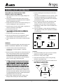
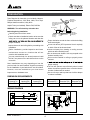
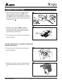
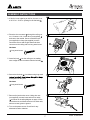
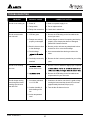
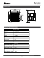
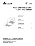
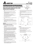
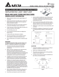
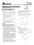
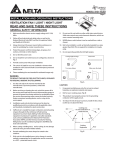
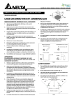
ITEM #809721
HUMIDITY SENSING
BATH FAN
MODEL VFB080D4H1
TABLE OF CONTENTS
Package Contents
2
General Safety Information
3
Preparation and Wiring Diagrams
4
Assembly Instructions - New Construction
5
Assembly Instructions - Existing Construction
6
Grille Installation
8
Humidity Sensing Fan Operation
8
Care and Maintenance
9
Troubleshooting
10
Dimensions
11
11
Warranty
12
READ AND SAVE THESE INSTRUCTIONS
Address: 4405 Cushing Parkway, Fremont, CA 94538
US Toll Free Number: 1-888-979-9889
Scan here for product video
PACKAGE CONTENTS
1
PART
DESCRIPTION
QTY
1
Fan Body
1
2
Grille
1
3
Suspension Bracket I
1
4
Suspension Bracket II
1
5
Suspension Bracket III
1
6
Duct Connector
1
HARDWARE CONTENTS
(Images are to scale)
2
X4
A
Long Wood Screw (
3
B
4 x 25)
X3
Short Machine Screw (M4 x 12)
4
5
6
Model: VFB080D4H1
2
GENERAL SAFETY INFORMATION
READ AND SAVE THESE INSTRUCTIONS
GENERAL SAFETY INFORMATION
6. Ducted ventilating fans must always be vented to the
outdoors.
1. Make sure that the electric service supply voltage is AC
120V, 60Hz.
7. If this unit is to be installed over a tub or shower, it must
be marked as appropriate for the application and be
connected to a GFCI (Ground Fault Circuit lnterrupter) –
protected branch circuit.
2. Follow all local electrical and safety codes, as well as
the National Electrical Code (NEC) and the Occupational
Safety and Health Act (OSH Act).
8. Do not use this unit with any other solid-state control
device. Solid-state controls may cause harmonic
distortion, which can cause a motor humming noise.
3. Always disconnect the power source before working on or
near the ventilating fan, motor or junction box.
9. NEVER place a switch where it can be reached from a
tub or shower.
4. Protect the power cord from sharp edges, oil, grease, hot
surfaces, chemicals or other objects.
10. Not to be installed in a ceiling thermally insulated to a
value greater than R40. (This is required for installation
in Canada only).
5. Do not kink the power cord.
6.
shown in Fig.A.
Turning angle too large
7. Provide suction parts with proper ventilation.
Duct shrink
8. This unit is UL Listed for use over a bathtub or shower
when installed in a GFCI protected branch circuit.
9. These ventilating fans are intended for residential usage
only.
Too m an y elbow s
Elbow near the body
Turning angle too large
Duct shrink
Body
WARNING
TO REDUCE THE RISK OF FIRE, ELECTRIC SHOCK, OR
INJURY TO PERSONS, OBSERVE THE FOLLOWING:
Minimum 18 in.
Too m an y elbow s
1. Use this unit only in the manner intended by the
manufacturer. If you have questions, contact the
manufacturer.
Elbow near the body
Fig. A
Body
CAUTION
2. Before servicing or cleaning the unit, switch the power off
at the service panel and lock the service disconnecting
means to prevent the power from being switched on
accidentally. When the service disconnecting means
cannot be locked, securely fasten a prominent warning
device, such as a tag, to the service panel.
1. For general ventilating use only. Do not use to exhaust
Minimum 18 in.
hazardous or explosive materials and vapors.
2. Not for use in cooking areas. (Fig.B)
3. This product must properly
connect
Cooking
area to the grounding
Do not circuit.
install above or
conductor of the supply
inside this area
3. Installation work and electrical wiring must be done by
4. To reduce the risk of injury to persons, install the fan at
45 °
4.
burning equipment to prevent backdrafting. Follow the
heating equipment manufacturer’s guideline and safety
standards such as those published by the National Fire
Protection Association (NFPA), and the American Society
for Heating Refrigeration and Air Conditioning Engineers
(ASHRAE) and local code authorities.
45 °
Cooking area
Do not install above or
inside this area
Cooking
Equipment
Cooking
Equipment
5. When cutting or drilling into the wall or ceiling, do not
damage electrical wiring and other hidden utilities.
45°
45°
floor
floor
Fig. B
3
Model: VFB080D4H1
PREPARATION
Tools Required for Assembly (not included): Hammer,
Flathead Screwdriver, Wire Nuts, Nails, Duct Tape,
Phillips Head Screwdriver, Utility Knife
Roof cap
(with built-in
damper)
Short piece of flexible
duct helps alignment
and absorbs
sound
Helpful Tools (not included): Electric Drill, Drill Bits
Fan housing
WARNING: Turn off electricity at breaker box
before beginning installation.
or
Carefully remove unit from carton.
Seal gap
around
housing
Check area above installation location to be sure that
wiring can run to the planned location and that duct
Caulk termination
to duct
Wall cap
(with built-in
damper)
Proper insulation around the fan to minimize building
heat loss and gain.
Locate unit above (GFCI-protected circuit required)
or within 5 feet of the shower head.
Locate unit away from heating or cooling sources
which can affect humidity levels.
Do not locate near window. Unit may respond to the
outdoor humidity level.
Unit must be installed in ceiling to properly sense
moisture.
proper ventilation.
Inspect duct work and wiring before proceeding with
installation.
Before installation, provide inspection and future
maintenance access at a location that will not
interfere with installation work.
You may need the help of a second person to install
this fan: one person on the attic side and one on the
room side.
Note: Installations may vary depending on how the
previous bath fan was installed. Supplies necessary
for the installation of your bath fan are not all included.
However, most are available at your local home
improvement or hardware store.
proper sensing.
The fan will operate most efficiently when located
where the shortest possible duct run and minimum
number of elbows will be needed.
Use a roof cap or wall cap that has a built-in damper
to reduce backdrafts.
DIMENSION REQUIREMENTS
Ceiling
Opening (L)
Ceiling
Opening (W)
Ceiling
Opening (H)
Housing
Dimension (L)
Housing
Dimension (W)
Housing
Dimension (H)
10.25 in.
10.25 in.
8.5 in.
9.68 in.
9.68 in.
7.98 in.
WIRING DIAGRAM
BLACK
WHITE
SWITCH BOX
JUNCTION BOX
BLACK
OFF
ON
WHITE
GREEN
POWER SWITCH
L
ON/OFF SWITCH
(purchase separately)
SWITCH BOX
N
GRD
WIRING
PLATE
POWER
SWITCH
120 VAC
LINE IN
Model: VFB080D4H1
GROUND
(bare)
4
ASSEMBLY INSTRUCTIONS
NEW CONSTRUCTION – ATTACHING TO THE JOIST
BEFORE INSTALLATION
Turn off power source. Review all safety precautions.
1
1. If spacing between joists is 12 in. apart, use four
long wood screws (provided) to attach the fan body
1 to ceiling joists.
3
3
1
1
Hardware
A
4
4
5
5
Long wood screw
A
2
2. For joist spacing 16 in. - 24in., insert suspension
bracket I 3 into the bracket cover on the duct
connector side. Then, attach suspension bracket II
4 and bracket III 5 to the back of the fan body 1 .
3
1
4
5
3
3. Secure the fan body 1 to the joist with suspension
brackets 3 , 4 , 5 using long wood screws.
1
1
Hardware
A
4
4
Long wood screw
A 5
A 5
4
4. Secure the suspension brackets 4 , 5 to the fan
body 1 using a short machine screw.
1
1
Hardware
B
4
4
1
Short machine screw
4
5
5
Short
machineShort
screw
machine screw
A
5
5
1
Model: VFB080D4H1
ASSEMBLY INSTRUCTIONS
5. Remove the fan junction box cover a . Using wire
nuts (not supplied), connect house wires to fan
wires b as shown in the wiring diagram on page 4.
Wire connections are as follows: black to live switch
wire, white to neutral, green to ground. Reattach fan
junction box cover c .
5
b
a
b
a
c
c
6
6. Connect a 4 in. circular duct a (not supplied)
and vent to the outside. Secure it with duct tape
(not supplied) or clamp (not supplied) to make the
connection secure and air tight.
a
a
7. Turn on power source. Check fan for any abnormal
sound or vibration.
EXISTING CONSTRUCTION – ACCESSIBLE FROM ABOVE
BEFORE INSTALLATION
1
Turn off power source. Review all safety precautions.
1. Remove existing fan.
2
2. Measure the opening to ensure it is large enough to
accommodate the new fan body (10.25 in. x 10.25
in.).
Model: VFB080D4H1
6
ASSEMBLY INSTRUCTIONS
3
3. If this fan is not replacing an old fan, be sure to cut
a 10.25 in. x 10.25 in. opening for the fan body 1 .
.4"in.
5
10.29
10
n.
.4i"
.295
4. Place the duct connector 6 through the ceiling cut
out. Connect a 4 in. circular duct (not supplied) a
and vent to the outside. Secure it with duct tape
(not supplied) or clamp (not supplied) to make
connection secure and air tight. Attach the duct
connector to the ceiling with one long wood screw.
4
a
A
6
Hardware
A
Long wood screw
5
1
5. Insert fan body 1 into the ceiling cut out making
sure to align the duct connector with the fan body 1 .
6. Secure the fan body 1 from below using long wood
6
and drywall into the joists.
1
Hardware
A
A
Long wood screw
7
7. Remove fan junction box cover. Using wire nuts
(not supplied), connect house wires to fan wires
a as shown in the wiring diagram on page 4. Wire
connections are as follows: black to live switch wire,
white to neutral, green to ground.
a
8. Turn on the power source. Check fan for any
abnormal sound or vibration.
7
Model: VFB080D4H1
GRILLE INSTALLATION
Attach grille 1 by pinching mounting springs a and
insert into the narrow rectangular slots in fan body 1 .
a
1
2
HUMIDITY SENSING FAN OPERATION
1
1. Humidity Sensing Mode: Flip wall switch to “ON”
position. The LED indicator light in the fan will be
BLUE. The fan will automatically start when the
humidity level in the room is above 60%.
If humidity level is below 60%, the fan will stop
automatically.
2
Blue LED Light
Blue LED Light
2. Full Speed Mode: Cycle wall on/off switch. LED
indicator light in fan will be AMBER.
Amber LED Light
Amber LED Light
3
3. Fan Off: Move wall on/off switch to “OFF” position.
Model: VFB080D4H1
8
CARE AND MAINTENANCE
See safety information before proceeding. Routine maintenance should be done at least once a year.
• Never use solvents, thinner or harsh chemicals when cleaning the fan.
• Do not allow water to enter the motor.
1
• Do not immerse metal parts in water.
• Do not immerse resin parts in water over 140º Fahrenheit.
Turn off power source. Review all safety precautions.
1. To remove grille 2 , squeeze springs and pull down.
2
2
2. Wash and clean the grille 2 in a sink and dry with a
cloth.
2
3. Remove dust and dirt from the fan body 1 with a vacuum
cleaner.
3
Vacuum
cleaner
1
4. Dampen cloth with dust detergent and wipe the fan body
1 . Then wipe dry with a clean cloth.
4
1
5
5. Replace grille 2 back onto fan body 1 .
6. Turn on power source to operate fan again.
2
9
Model: VFB080D4H1
TROUBLESHOOTING
PROBLEM
The fan is not turning on
The fan seems louder
than it should
POSSIBLE CAUSE
CORRECTIVE ACTION
1. Power off
1. Make sure power supply is on.
2. Faulty switch
2. Test or replace switch.
3. Faulty wire connection
3. Check wire in switch box.
1. CFM too great
1. Be sure the CFM rating on the fan matches the
size of your room.
2. Damper not working
properly or damaged
2. Check damper to ensure it is opening and closing
properly. If the damper has become damaged,
please call Customer Service.
3. Bend in duct too close
to fan discharge
3. Be sure you do not have any sharp bends in duct
closer than 18 in. to the fan discharge.
4. Fan discharge
4. Use recommended size ducting to reduce fan
noise.
duct
The fan is not clearing
the room
The fan keeps running
even though the house
humidity level is lower
than 60% RH
5. Fan body not securely
attached
5. Be sure the fan is securely attached to your ceiling
joists.
1.
1. Be sure a door or window is slightly ajar or opened
airfow within room
2.
2. Be sure the CFM rating on the fan matches the
requirements for your room size.
1. Our sensor tolerance
is +/-10% RH
1. Continue to let the fan run since it is good to keep
venting the house and the electric bill is minimal
(approximately less than $10 per year).
2. Outdoor humidity is
back drafting to the
fan
2. Turn the fan off when not in use.
3. Indoor temperature
level
Model: VFB080D4H1
10
DIMENSIONS
PRODUCT SPECIFICATIONS
SPECIFICATIONS
Model No.
VFB080D4H1
80 CFM
Noise
≤ 0.3 Sones
Voltage
110-220V
Hertz
50-60Hz
Power Consumption
9.0 W
Duct diameter
4 in.
Weight
7.52 lbs.
Dimension
Ceiling opening – length
10.25 in.
Ceiling opening – width
10.25 in.
Ceiling opening – height
8.5 in.
Housing dimension – length
9.68 in.
Housing dimension – width
9.68 in.
Housing dimension – height
7.98 in.
11
Model: VFB080D4H1
WARRANTY
DELTA ELECTRONICS THREE YEAR LIMITED WARRANTY
Delta Electronics Inc. (“Delta Electronics”) warrants to the original consumer purchaser in the USA that the Breez
ventilation fan products will be free from defects in material or workmanship. This warranty is limited to three (3)
years from the original date of purchase.
Limitations and Exclusions
1. During the warranty period, a replacement for any defective product will be supplied free of charge for installation
by the consumer. The warranty provided herein does not cover charges for labor or other costs incurred in the
troubleshooting, repair, removal, and installation service.
2. All returns of defective parts or products must include the product model number, and must be made through an
authorized Delta Electronics distributor. Authorized returns must be shipped prepaid. Repaired or replacement
products will be shipped by Delta Electronics F.O.B. shipping point.
3. Delta Electronics shall not be liable for any indirect, incidental, consequential, punitive, or special damages
arising out of or in connection with products use or performance, regardless of the form of action whether in
contract, tort (including negligence), strict product liability or otherwise.
4.
5. The warranty does not cover if user does not comply with manufacturer’s installation manual.
6. To qualify for warranty service, you must notify Delta Electronics at the address or telephone number below.
7. Delta Electronics shall have no liability to the original owner-user with respect to any defect caused by abuse,
misuse, neglect, improper transportation or storage, improper testing, improper installation, improper operation,
accident of products or parts thereof, or unusual deterioration or degradation of products or parts thereof due to
Address: 4405 Cushing Parkway, Fremont, CA 94538
US Toll Free Number: 1-888-979-9889
Model: VFB080D4H1
12