1
INSTALLATION IN A
NEW CONSTRUCTION SITE
DUCT
COLLAR
FLANGES
PREPARATION
Refer to Figure 1.
1. To remove blower/power unit assembly from housing:
A. Unplug power unit.
B. Remove screw (located next to plug-in receptacle)
which holds blower/power unit mounting plate in place.
Save screw.
C. Lift mounting plate at end near the plug-in receptacle
until blower wheel clears the scroll.
D. Remove plate by pulling its tabs out of slots in housing.
Set blower/power unit aside until needed.
2. Remove one of the wiring knockout from housing.
WIRING
KNOCKOUTS
MOUNTING
TABS
MOUNTING THE HOUSING
FIGURE 2
Mounting Using Mounting Tabs
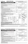
Refer to Figure 2.
1. Locate fan housing next to ceiling joist.
2. Use wood screws (not provided) to loosely attach the housing to ceiling joist through the keyhole slots in mounting tabs.
3. Adjust housing so that it will be flush with finished ceiling.
For the grille to fit properly, housing’s rim must not extend
beyond finished ceiling surface.
4. When housing is properly adjusted, tighten screws in slots.
HANGER BARS
(SOLD SEPARATELY)
Mounting Using Hanger Bars
(Hanger bars sold separately, order model HB4)
Refer to Figure 3.
1. Insert hanger bars in slots provided in housing.
2. Locate fan housing between joists so that the bottom of the
housing is even with the planned finished ceiling. Extend
the hanger bars to the joists.
3. Use screws or nails (not provided) to secure hanger bars
to ceiling joists.
FIGURE 3
INSTALLING THE DUCTWORK
1. Refer to Figure 2. Place duct collar over flanges at
discharge opening of fan. Secure collar by snapping tabs into slots in flanges.
2. Run 4” round duct from outside to fan’s discharge opening.
3. Connect duct to fan’s duct collar.
JUNCTION BOX
WIRING
All wiring must comply with local codes and unit must
be properly grounded.
1. Run 120vAC house wiring (with ground) from wall switch to fan location.
2. Pull wire through access hole and into junction box.
3. Refer to Figure 4. Use approved wire nuts to connect
house supply wires to fixture wires as follows: white to
white; black to black. Connect green or bare ground wire to green ground lead.
POWER/BLOWER UNIT INSTALLATION
1. Place power/blower unit into housing so that mounting
plate’s tabs insert into slots in housing.
2. Press other end of mounting plate down until it is firmly
seated over scroll and plug-in receptacles.
3. Secure mounting plate to housing with provided screw.
4. Insert motor plug into junction box receptacle.
GREEN
GROUND
LEAD
STANDARD WALL SWITCH
(NOT INCLUDED) OR
OPTIONAL NUTONE
SPEED CONTROL
120vAC, 60 Hz
HOUSE POWER
SWITCH
BOX
EARTH GROUND
FIGURE 4