1
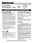
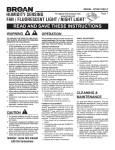
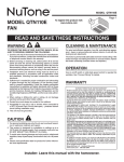
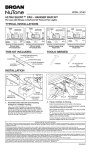
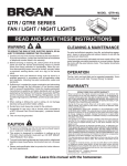
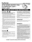
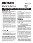
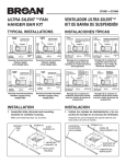
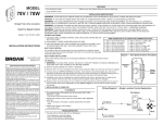
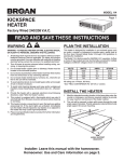
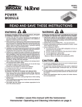
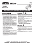
MODELS QTR050F • QTRE080 • QTRE110
QTR / QTRE SERIES
To register this product visit:
VENTILATORS
www.broan.com
Page 1
READ AND SAVE THESE INSTRUCTIONS
WARNING
TO REDUCE THE RISK OF FIRE, ELECTRIC SHOCK, OR INJURY TO PERSONS, OBSERVE THE FOLLOWING:
1. Usethisunitonlyinthemannerintendedbythemanufacturer.
Ifyouhavequestions,contactthemanufacturerattheaddress
ortelephonenumberlistedinthewarranty.
2. Beforeservicingorcleaningunit,switchpoweroffatservice
panel and lock the service disconnecting means to prevent
powerfrombeingswitchedonaccidentally.Whentheservice
disconnecting means cannot be locked, securely fasten a
prominentwarningdevice,suchasatag,totheservicepanel.
3. Installation work and electrical wiring must be done by a
qualified person(s) in accordance with all applicable codes
and standards, including fire-rated construction codes and
standards.
4. Sufficientairisneededforpropercombustionandexhausting
of gases through the flue (chimney) of fuel burning equipment to prevent backdrafting. Follow the heating equipment
manufacturer’sguidelineandsafetystandardssuchasthose
publishedbytheNationalFireProtectionAssociation(NFPA),
andtheAmericanSocietyforHeating,RefrigerationandAir
ConditioningEngineers(ASHRAE),andthelocalcodeauthorities.
5. When cutting or drilling into wall or ceiling, do not damage
electricalwiringandotherhiddenutilities.
6. Ductedfansmustalwaysbeventedtotheoutdoors.
7. Acceptableforuseoveratuborshowerwhenconnectedto
aGFCI(GroundFaultCircuitInterrupter)-protectedbranch
circuit(ceilinginstallationonly).
8. Thisunitmustbegrounded.
CAUTION
1. Forgeneralventilatinguseonly.Donotusetoexhausthazardousorexplosivematerialsandvapors.
2. This product is designed for installation in ceilings up to a
12/12pitch(45degreeangle).Ductconnectormustpointup.
DONOTMOUNTTHISPRODUCTINAWALL.
3. Toavoidmotorbearingdamageandnoisyand/orunbalanced
impellers,keepdrywallspray,constructiondust,etc.offpower
unit.
4. Pleasereadspecificationlabelonproductforfurtherinformationandrequirements.
CLEANING & MAINTENANCE
Forquietandefficientoperation,longlife,andattractiveappearance-lowerorremovegrilleandvacuuminteriorofunitwiththe
dustingbrushattachment.
Themotorispermanentlylubricatedandneverneedsoiling.Ifthe
motorbearingsaremakingexcessiveorunusualnoises,replace
theblowerassembly(includesmotorandimpeller).
OPERATION
Useanon/offswitchorspeedcontroltooperatethisventilator.See
“ConnectWiring”fordetails.Useofspeedcontrolsotherthanthe
BroanModels78Vand78Wmaycauseamotorhummingnoise.
WARRANTY
BROAN-NUTONETHREEYEARLIMITEDWARRANTY
Broan-NuTonewarrantstotheoriginalconsumerpurchaserofitsproductsthat
suchproductswillbefreefromdefectsinmaterialsorworkmanshipforaperiodofthreeyearsfromthedateoforiginalpurchase.THEREARENOOTHER
WARRANTIES,EXPRESSORIMPLIED,INCLUDING,BUTNOTLIMITEDTO,
IMPLIEDWARRANTIESOFMERCHANTABILITYORFITNESSFORAPARTICULARPURPOSE.
Duringthisthree-yearperiod,Broan-NuTonewill,atitsoption,repairorreplace,
withoutcharge,anyproductorpartwhichisfoundtobedefectiveundernormal
useandservice.
THIS WARRANTY DOES NOT EXTEND TO FLUORESCENT LAMP
STARTERS, TUBES, HALOGEN AND INCANDESCENT BULBS, FUSES,
FILTERS, DUCTS, ROOF CAPS,WALL CAPSAND OTHERACCESSORIES
FOR DUCTING. This warranty does not cover (a) normal maintenance and
service or (b) any products or parts which have been subject to misuse,
negligence, accident, improper maintenance or repair (other than by BroanNuTone),faultyinstallationorinstallationcontrarytorecommendedinstallation
instructions.
Thedurationofanyimpliedwarrantyislimitedtothethree-yearperiodasspecifiedfortheexpresswarranty.Somestatesdonotallowlimitationonhowlongan
impliedwarrantylasts,sotheabovelimitationmaynotapplytoyou.
BROAN-NUTONE’S OBLIGATION TO REPAIR OR REPLACE, AT BROANNUTONE’SOPTION,SHALLBETHEPURCHASER’SSOLEANDEXCLUSIVE
REMEDYUNDERTHISWARRANTY.BROAN-NUTONESHALLNOTBELIABLEFORINCIDENTAL,CONSEQUENTIALORSPECIALDAMAGESARISING
OUTOFORINCONNECTIONWITHPRODUCTUSEORPERFORMANCE.
Somestatesdonotallowtheexclusionorlimitationofincidentalorconsequential
damages,sotheabovelimitationorexclusionmaynotapplytoyou.
Thiswarrantygivesyouspecificlegalrights,andyoumayalsohaveotherrights,
whichvaryfromstatetostate.Thiswarrantysupersedesallpriorwarranties.
Toqualifyforwarrantyservice,youmust(a)notifyBroan-NuToneattheaddress
ortelephonenumberbelow,(b)givethemodelnumberandpartidentification
and(c)describethenatureofanydefectintheproductorpart.Atthetimeof
requestingwarrantyservice,youmustpresentevidenceoftheoriginalpurchase
date.
Broan-NuToneLLC,926W.StateStreet,Hartford,Wisconsin53027
www.broan.com800-558-1711
Installer: Leave this manual with the homeowner.
MODELS QTR050F • QTRE080 • QTRE110
TYPICAL INSTALLATIONS
Housing mounted
to I-joists.
Housing mounted
anywhere
between
I-joists
using
hanger bars.
Page 2
Housing mounted
anywhere
between trusses
using hanger
bars.
PLAN THE INSTALLATION
COOKING AREA
Do not install above or
inside this area.
45o
Housing mounted
to joists.
NOT FOR USE IN
A COOKING AREA.
45o
Cooking
Equipment
Floor
INSULATION
(Canbeplaced
aroundandover
fanhousing.)
ROOF
CAP*
Housing mounted
anywhere
between
joists
using
hanger bars.
FAN
HOUSING
Housing mounted
anywhere
between trusses
using hanger
bars.
*Purchase
4-IN.
ROUND
DUCT*
separately
4-IN.ROUND
ELBOW(S)*
WALL
CAP*
The unit will operate most quietly and efficiently when located
wheretheshortestpossibleductrunandminimumnumberof
elbowswillbeneeded.
Usearoofcaporwallcapthathasabuilt-indampertoreduce
backdrafts.
Plantosupplytheunitwithproperlinevoltageandappropriate
powercable.
MODELS QTR050F • QTRE080 • QTRE110
Page 3
INSTALL HOUSING & DUCT
1a. Mount
housing to
joist or I-joist.
Useaplierstobend
housingTABSout
to900.Holdhousing
inplacesothat
thehousingtabs
contactthebottom
ofthejoist.The
housingmounts
withfour(4)screws
ornails.Screwor
nailhousingtojoist
throughlowest
holesineach
mountingflange,
thenthrough
highestholes.
NOTE:Mountingto
I-JOIST(shown)
requiresuse
ofSPACERS
(included)between
thehighesthole
ofeachmounting
flangeandthe
I-joist.
HOLEFOROPTIONAL
SCREWMOUNTING(4)
TABS
SPACER
(useformountingtoI-Joist)
NAIL(4)
BOTTOMEDGE
OFFRAMING
ExtendHANGERBARStothewidthoftheframing.
I-JOIST
Hold ventilator in place with the hanger bar tabs wrapping
aroundtheBOTTOMEDGEOFTHEFRAMING.
NAILventilatortoframingorfastenwithscrews(notprovided)
throughHOLESnearnails.
Toensureanoise-freemount:Securehangerbarstogether
*with
SCREWS or use a pliers to crimp mounting channels
tightlyaroundhangerbars.
OR
1b. Mount housing anywhere between
trusses, joists, or I-joists using hanger
bars.
Slidinghangerbarsareprovidedtoallowforaccuratepositioningofhousinganywherebetweenframing.Theycanbe
usedonalltypesofframing(I-joist,standardjoist,andtruss
construction)andspanupto24”.
TAB
2. Attach damper/
duct connector.
Snapdamper/duct
connectorontohousing.
Makesureconnectoris
flushwithtopofhousing
anddamperflapfalls
closed.
SCREWS(4)
ST
D
3. Install 4-inch
round ductwork.
HANGER
BAR(4)
*SCREW(2)
MOUNTING
CHANNEL(2)
Attach the MOUNTING CHANNELS to the housing using the
SCREWSsupplied.MakesureTABSface“up”asshown.Use
thesetofchannelmountingholes(marked“STD”)tomountthe
housingflushwiththebottomofthedrywall.Usetheotherset
ofholes(notmarked)tomountthehousingflushwiththetopof
thedrywall.
Connect4-inchround
ductworktodamper/duct
connector.Runductwork
toaroofcaporwall
cap.Tapeallductwork
connectionstomake
themsecureandairtight.
MODELS QTR050F • QTRE080 • QTRE110
Page 4
CONNECT WIRING
INSTALL GRILLE
5. Finish ceiling.
Installceilingmaterial.Cutoutaroundhousing.
6. Attach grille
to housing.
4. Connect electrical wiring.
Squeezegrille
springsandinsert
themintoslots
oneachsideof
housing.
7. Push grille
against
ceiling.
Run120VAChousewiringtoinstallationlocation.Use
properULapprovedconnectortosecurehousewiringto
wiringplate.Connectwiresasshowninwiringdiagrams.
SERVICE PARTS
Key No.
1
2
3
4
5
6
7
8
9
10
11
Part No.
97016466
97016449
98010102
99170245
97018010
97017782
97017783
97017854
97016497
99140199
97018014
QTHB1
99420665
Description
Housing
DuctConnector-4”
WiringPlate
Screw,#8-18X.375
WirePanel/HarnessAssembly
BlowerAssembly(QTR050F)
BlowerAssembly(QTRE080)
BlowerAssembly(QTRE110)
GrilleAssembly
(includeskeyno.8)
GrilleSpring(2req’d)
Spacer(2supplied)
HangerBars(QTRE080,QTRE110)
Thumbscrew,#8-18x.375
Replacement parts
can be ordered on our
website. Please visit
us at www.broan.com
Orderservicepartsby“PartNo.”-notby“KeyNo.”
SERVICE NOTEToremoveBlowerAssembly:Unplugmotor.
Removethumbscrew(11)frommotorplateflange.Findthe
singleTABonthemotorplate(locatednexttothereceptacle).
Pushupnearmotorplatetabwhilepushingoutonsideof
housing.Orinsertastraight-bladescrewdriverintoslotin
housing(nexttotab)andtwistscrewdriver.
99044371B
MODELOS QTR050F • QTRE080 • QTRE110
este producto visite:
VENTILADORES Para registrar
www.broan.com
SERIE QTR / QTRE
Página 5
LEA Y CONSERVE ESTAS INSTRUCCIONES
ADVERTENCIA
LIMPIEZA Y MANTENIMIENTO
PARA REDUCIR EL RIESGO DE INCENDIOS, DESCARGAS
ELÉCTRICAS O LESIONES PERSONALES, OBSERVE LAS
SIGUIENTES PRECAUCIONES:
1. Uselaunidadsólodelamaneraindicadaporelfabricante.Si
tienepreguntas,comuníqueseconelfabricantealadirección
oalnúmerotelefónicoqueseincluyenenlagarantía.
2. Antesdedarservicioalaunidadodelimpiarla,interrumpael
suministroeléctricoenelpaneldeservicioybloqueelosmediosdedesconexióndelservicioparaevitarquelaelectricidad
sereanudeaccidentalmente.Cuandonoseaposiblebloquear
los medios de desconexión del servicio, fije firmemente un
dispositivodeadvertencia(porejemplo,unaetiqueta)enun
lugarprominentedelpaneldeservicio.
3. Eltrabajodeinstalaciónyelcableadoeléctricodebenserrealizadosporunaomáspersonascalificadas,ydebencumplir
contodosloscódigosynormascorrespondientes,incluidoslos
códigosynormasdeconstrucciónespecíficosdeprotección
contraincendios.
4. Se necesita suficiente aire para que se lleve a cabo una
combustión adecuada y para la descarga de los gases a
travésdeltubodehumos(chimenea)delequipoquemador
decombustible,afindeevitarlascontracorrientes.Sigalas
directricesynormasdeseguridaddelfabricantedelequipo
decalentamiento,talescomolaspublicadasporlaAsociación
NacionaldeProteccióncontraIncendios(NationalFireProtectionAssociation,NFPA),laSociedadAmericanadeIngenieros
deCalefacción,RefrigeraciónyAireAcondicionado(American
SocietyforHeating,RefrigerationandAirConditioningEngineers,ASHRAE)ylasautoridadesdeloscódigoslocales.
5. Alcortaroperforaratravésdelaparedodelcieloraso,no
dañeelcableadoeléctriconiotrosserviciosocultos.
6. Los ventiladores con conductos deben siempre conectarse
haciaelexterior.
7. Esaceptableutilizaresteproductosobreunaregaderaotina
siseconectaauncircuitosecundarioprotegidoporunGFCI
(interruptoraccionadoporpérdidadeconexiónatierra)(instalacióndeltechosolamente).
8. Estaunidaddebeconectarseatierra.
Paralograrunfuncionamientosilenciosoyeficiente,comotambiénlargavidayunaaparienciaatractiva,bajeoretirelarejilla
yaspireelinteriordelaunidadconelaccesoriodelcepillopara
sacudirpolvo.
El motor está permanentemente lubricado y nunca necesitará
aceite.Siloscojinetesdelmotorestánhaciendoruidoexcesivo
oinusual,reemplaceelmotorconelmotordeservicioexacto.El
impulsortambiéndebeserreemplazado.
PRECAUCIÓN
1. Sóloparausarloenventilacióngeneral.Nolouseparadescargarmaterialesnivaporespeligrososoexplosivos.
2. Esteproductosediseñaparalainstalaciónentechoshasta
unaechadade12/12(ángulode45grados).NOMONTEESTE
PRODUCTOENUNATECHO.
3. Paraevitardañosaloscojinetesdelmotoryrotoresruidosos
y/onoequilibrados,mantengalaunidaddeaccionamientoal
resguardoderocíodeyeso,polvodelaconstrucción,etc.
4. Lea la etiqueta de especificaciones del producto para ver
informaciónyrequisitosadicionales.
OPERACIÓN
Opere este ventilador mediante un interruptor de encendido/
apagadoocontroldevelocidad.Vealosdetallesenlasección
“Conexióneléctrica”.Elusodeloscontrolesdelavelocidadcon
excepcióndelosmodelos78Vy78WdeBroanpuedecausar
unruidodeltarareodelmotor.
GARANTÍA
GARANTIABROAN-NUTONELIMITADAPORTRESAÑOS
Broan-NuTonegarantizaalconsumidorcompradororiginaldesusproductosquedichos
productoscarecerándedefectosenmaterialesoenmanodeobraporunperíodode
tresañosapartirdelafechaoriginaldecompra.NOEXISTENOTRASGARANTIAS,
EXPLICITASOIMPLICITAS,INCLUYENDO,PERONOLIMITADASA,GARANTIASIMPLICITASDECOMERCIALIZACIONOAPTITUDPARAUNPROPOSITOPARTICULAR.
Duranteelperíododetresaños,yasupropiocriterio,Broan-NuTonerepararáoreemplazará,sincostoalgunocualquierproductoopiezaqueseencuentredefectuosa
bajocondicionesnormalesdeservicioyuso.
LA PRESENTE GARANTÍA NO CUBRE LOS TUBOS FLUORESCENTES NI
SUS ARRANCADORES, BOMBILLAS DE HALÓGENO E INCANDESCENTES,
FUSIBLES,FILTROS,CONDUCTOS,TAPONESDETECHOOPAREDESYDEMÁS
ACCESORIOS PARA CONDUCTOS. Esta garantía no cubre (a) mantenimiento y
servicionormaleso(b)cualquierproductoopiezasquehayansidoutilizadasdeforma
errónea,negligente,quehayancausadounaccidente,oquehayansidoreparadas
omantenidasinapropiadamente(porotrascompañíasquenoseanBroan-NuTone),
instalación defectuosa, o instalación contraria a las instrucciones de instalación
recomendadas.
Laduracióndecualquiergarantíaimplícitaselimitaaunperíododetresañoscomo
se especifica en la garantía expresa.Algunos estados no permiten limitaciones en
cuantoaltiempodeexpiracióndeunagarantíaimplícita,porloquelalimitaciónantes
mencionadapuedenoaplicarseausted.
LAOBLIGACIONDEBROAN-NUTONEDEREPARAROREEMPLAZAR,SIGUIENDO
ELCRITERIODEBROAN-NUTONE,DEBERASERELUNICOYEXCLUSIVORECURSOLEGALDELCOMPRADORBAJOESTAGARANTIA.BROAN-NUTONENO
SERARESPONSABLEPORDAÑOSINCIDENTALES,CONSIGUIENTES,OPOR
DAÑOSESPECIALESQUESURJANARAIZDELUSOODESEMPEÑODELPRODUCTO.Algunosestadosnopermitenlaexclusiónolimitacióndedañosincidentales
oconsiguientes,porloquelalimitaciónantesmencionadapuedenoaplicarseausted.
Estagarantíaleproporcionaderechoslegalesespecíficos,yustedpuedetambiéntener
otrosderechos,loscualesvaríandeestadoaestado.Estagarantíareemplazatodas
lasgarantíasanteriores.
Paracalificarenlagarantíadeservicio,usteddebe(a)notificaraBroan-NuToneal
domiciliooalnúmerodeteléfonoquesemencionaabajo,(b)darelnúmerodelmodelo
ylaidentificacióndelapieza,y(c)describirlanaturalezadecualquierdefectoenel
productoopieza.Enelmomentodesolicitarserviciocubiertoporlagarantía,usted
debedepresentarevidenciadelafechaoriginaldecompra.
Broan-NuToneLLC,926W.StateStreet,Hartford,Wisconsin53027
www.broan.com800-558-1711
A la persona que realiza la instalación: Deje este manual con el dueño de la casa.
MODELOS QTR050F • QTRE080 • QTRE110
Página 6
INSTALACIONES TÍPICAS
Montaje de la
cubierta en
viguetas “I”.
Montaje de
la cubierta
en cualquier
parte entre las
viguetas “I” por
medio de barras
de suspensión.
Montaje de la
cubierta en
cualquier parte
entre armaduras
por medio
de barras de
suspensión.
PLANIFICACIÓN DE LA
INSTALACIÓN
ÁREA QUE COCINA
No instale sobre o dentro
de esta área.
45o
Montaje de
cubierta en
viguetas.
NO PARA EL
USO EN UN
ÁREA QUE COCINA.
45o
Equipo
para cocinar
Piso
Montaje de
la cubierta
en cualquier
parte entre las
viguetas por
medio de barras
de suspensión.
Montaje de la
cubierta en
cualquier parte
entre armaduras
por medio
de barras de
suspensión.
AISLAMIENTO
(Puede ser colocado alrededor y
sobre de la cubierta
del ventilador.)
CUBIERTA DE
VENTILADOR
CONDUCTO
REDONDO DE
4 PULG. *
* Se compran
CODO REDONDO
por separado
DE 4 PULG. *
TAPA DE
TECHO *
TAPA
DE
PARED*
Elventiladorfuncionaráconmáseficienciaymenosruidosiseubica
enunsitiodonderequieraeltramodeconductomáscortoposibley
unmínimonúmerodecodos.
Instaleunatapadetechoodeparedquetengaunreguladordetiro
incorporadoafindereducirloscontratiros.
Alimentelaunidadconelvoltajedelíneayelcableeléctricoapropiados.
MODELOS QTR050F • QTRE080 • QTRE110
Página 7
INSTALE LA CUBIERTA Y EL
CONDUCTO
1a. Instale la
cubierta en
las viguetas o
viguetas “I”.
ORIFICIOPARAMONTAJE
CONTORNILLOOPCIONAL(4)
Conunalicate,doble
lasLENGÜETAS
delacubiertaa90°.
LENGÜETAS
Sostengalacubierta
ensulugardemanera
quelaslengüetas
delacubiertahagan
contactoconlaparte
SEPARADOR(seusapara
inferiordelavigueta.
elmontajealavigueta“I”)
Paraelmontajede
lacubiertaseutilizan
cuatro(4)tornillos
oclavos.Atornilleo
clavelacubiertaa
laviguetaatravés
delosorificios
másbajosdecada
bridademontaje,
yseguidamentea
travésdelosmás
VIGUETA“I”
altos.NOTA:Parael
montajeenlaVIGUETA “I”,talcomoseilustra,serequiere
utilizarSEPARADORES(incluidos)entreelorificiomásaltode
cadabridademontajeylavigueta“I”.
O BIEN
1b. Instale la cubierta en cualquier parte
entre las armaduras, viguetas o viguetas
“I” por medio de barras de suspensión.
Seproporcionanbarrasdesuspensióndeslizantesparafacilitar
lacolocaciónadecuadadelacubiertaencualquierparteentrela
estructura.Estasbarrasseadaptanatodaclasedeestructuras
(construccionesdeviguetas“I”,viguetasestándaryarmaduras)
yseextiendenaunmáximode61cm(24pulg.).
LENGÜETA
TORNILLOS(4)
CLAVO(4)
CANALDE
MONTAJE(2)
FijelosCANALESDEMONTAJEalacubiertaconlosTORNILLOS
incluidos.AsegúresedequelasLENGÜETASesténdecarahacia
arriba,talcomosemuestra.Utiliceeljuegodeorificiosdemontaje
del canal (marcados como “STD”) para montar la cubierta al ras
conlaparteinferiordelatablarroca.Utiliceelotrojuegodeorificios
(sinmarca)paramontarlacubiertaalrasconlapartesuperiorde
latablarroca.
BORDEINFERIORDE
LAESTRUCTURA
Abra las BARRAS DE SUSPENSIÓN hasta el ancho de la
estructura.
Sostengaelventiladorensusitioenvolviendolaslengüetasde
labarradesuspensiónalrededordelBORDEINFERIORDELA
ESTRUCTURA.
CLAVEelventiladoralaestructuraosujételocontornillos(no
incluidos)atravésdelosORIFICIOSqueestáncercadelosclavos.
Paralograrunmontajesilencioso:acopleyfijelasbarrasde
suspensiónconTORNILLOS,odobleloscanalesdemontajecon
unalicatebienjustosalrededordelasbarrasdesuspensión.
*
2. Acople el conector
del regulador
de tiro/conducto.
Conecteapresiónelconectordelreguladordetiro/
conductoenlacubierta.
Asegúresedequeelconectorestéalrasconlaparte
superiordelacubiertay
quelaaletadelregulador
caigacerrada.
ST
D
BARRADESUSPENSIÓN(4)
*TORNILLO(2)
3. Instale el
conducto
redondo de 4
pulgadas.
Conecteelconducto
redondode4pulgadasal
conectordelregulador/conducto.Extiendaelconducto
haciaunatapadetecho
otapadepared.Encinte
todaslasconexionesdelos
conductosparafijarlasy
hacerlasherméticasalaire.
MODELOS QTR050F • QTRE080 • QTRE110
Página 8
CONEXIÓN ELÉCTRICA
INSTALE LA REJILLA
5. Termine el cielo raso.
Instaleelmaterialdelcieloraso.Recortealrededordelacubierta.
6. Acople la
rejilla a la
cubierta.
4. Conecte los cables eléctricos.
Extiendaelcableadodelacasade120VCAallugardela
instalación.UtiliceunaconexiónaprobadaporULparaafianzarel
cableadodelacasaalaplacadecableado.Conecteloscables
talcomoseilustraenlosdiagramasdecableado.
Aprietelosresortesde
larejillaeinsértelos
enlasranurasquese
encuentranacadalado
delacubierta.
7. Empuje la
rejilla contra
el cielo raso.
PIEZAS DE REPUESTO
Clave n.o Pieza n.o
1
2
3
4
5
6
7
8
9
10
11
97016466
97016449
98010102
99170245
97018010
97017782
97017783
97017854
97016497
99140199
97018014
QTHB1
99420665
Descripción
Cubierta
Conectordelconducto(4pulg.)
Placadecableado
Tornillon.o8-18x0.375
Conjuntodelpaneldecableado/arnés
Conjuntodelventilador(QTR050F)
Conjuntodelventilador(QTRE080)
Conjuntodelventilador(QTRE110)
Conjuntodelarejilla
(incluyeclaven.o8)
Resortedelarejilla(serequieren2)
Separador(sesuministran2)
Juegodebarradesuspensión
(QTRE080,QTRE110)
Tornillodemariposan.o8-18x0.375
Las piezas de recambio se
pueden ahora pedir en
nuestro Web site. Visítenos
por favor en www.broan.com
Alhacerelpedidodeunapiezadeserviciosedebeespecificar
elnúmerodelapieza(noelnúmerodelaclave).
NOTA DE SERVICIOParadesmontarelconjuntodelventilador:Desenchufeelmotor.Saqueeltornillodemariposa
(11)delabridadelaplacadelmotor.LocalicelaLENGÜETA
únicadelaplacadelmotor(seencuentrajuntoalreceptáculo).
Empujehaciaarribacercadelalengüetadelaplacadelmotor
almismotiempoqueempujahaciaafueraelcostadodela
cubierta.Obien,introduzcaundestornilladordepuntarectaen
laranuradelacubierta(juntoalalengüeta)ygírelo.
99044371B