1
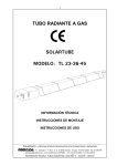
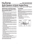
MODEL 751
Page VENTILATION FAN
WITH LIGHT
READ AND SAVE THESE INSTRUCTIONS
WARNING
Hanger Bars
TO REDUCE THE RISK OF FIRE, ELECTRIC SHOCK, OR INJURY
TO PERSONS, OBSERVE THE FOLLOWING:
1. Use this unit only in the manner intended by the manufacturer.
If you have questions, contact the manufacturer at the address
or telephone number listed in the warranty.
2. Before servicing or cleaning unit, switch power off at service panel
and lock the service disconnecting means to prevent power from
being switched on accidentally. When the service disconnecting
means cannot be locked, securely fasten a prominent warning
device, such as a tag, to the service panel.
3. Installation work and electrical wiring must be done by a qualified
person(s) in accordance with all applicable codes and standards,
including fire-rated construction codes and standards.
4. Sufficient air is needed for proper combustion and exhausting of
gases through the flue (chimney) of fuel burning equipment to prevent backdrafting. Follow the heating equipment manufacturer’s
guideline and safety standards such as those published by the
National Fire Protection Association (NFPA), and the American
Society for Heating, Refrigeration and Air Conditioning Engineers
(ASHRAE), and the local code authorities.
5. When cutting or drilling into wall or ceiling, do not damage electrical wiring and other hidden utilities.
6. Ducted fans must always be vented to the outdoors.
7. If this unit is to be installed over a tub or shower, it must be marked
as appropriate for the application and be connected to a GFCI
(Ground Fault Circuit Interrupter) - protected branch circuit.
8. Never place a switch where it can be reached from a tub or
shower.
9. To reduce the risk of electrical shock, do not use this fan with
any solid-state speed control.
10. Not for use in kitchens.
11. Do not install in a ceiling insulated to a value greater than R40.
12. This unit must be grounded.
CAUTION
Duct
Collar
Wiring
Knockouts
Housing
Slots
Tabs
FOR BEST RESULTS
When installing the Exhaust Fan/Light in a new construction site,
install housing during the rough-in construction of the building. The
blower unit, reflector and grille should be installed after the finished
ceiling is in place.
Power/Blower
Unit
Reflector
Assembly
Acorn Nut
Mounting
Springs (2)
Grille/Lens
Assembly
!
1. For general ventilating use only. Do not use to exhaust hazardous or explosive materials and vapors.
2. To avoid motor bearing damage and noisy and/or unbalanced
impellers, keep drywall spray, construction dust, etc. off power
unit.
3. Please read specification label on product for further information
and requirements.
Scroll
FIGURE 1
PLANNING DUCTWORK AND WIRING
DUCTWORK
1. Use 4” round duct.
2. Plan duct run from discharge opening of fan to the outside. For
best fan performance, make duct run as short as possible and
use minimum number of elbows.
3. Use optional Broan ducting accessories as needed.
WIRING
Plan to run 120 VAC house wiring (with ground) from power source,
through wall switch, to junction box in housing. For separate control
of fan and light use an optional Broan switch.
IMPORTANT: Use wire suitable for 90oC.
MODEL 751
Page INSTALLATION IN A
NEW CONSTRUCTION SITE
PREPARATION
1. Refer to Figure 1. Remove power unit/blower assembly from
housing.
A.Unplug power unit.
B.Remove screw (located next to plug-in receptacle) which holds
power/blower unit mounting plate in place. Save screw.
C.Lift mounting plate at end near the plug-in receptacle until blower
wheel clears the scroll.
D. Remove plate by pulling its tabs out of slots in housing. Set
power/blower unit aside until needed.
MOUNTING THE HOUSING
MOUNTNG USING MOUNTING TABS
Refer to Figure 2.
1. Locate fan housing next to ceiling joist.
2. Use wood screws (not provided) to loosely attach housing to
ceiling joist through the keyhole slots in mounting tabs.
3. Adjust housing so that it will be flush with finished ceiling. For the
grille to fit properly, the housing’s rim must not extend beyond
finished ceiling surface.
4. When housing is properly adjusted, tighten screws in slots.
MOUNTING USING HANGER BARS
Refer to Figure 3.
1. Insert hanger bars in slots provided in housing.
2. Locate fan housing between joists so that the bottom of the housing is even with the planned finished ceiling. Extend the hanger
bars to the joists.
3. Use screws or nails (not provided) to secure hanger bars to ceiling joists.
INSTALLING DUCTWORK
1. Refer to Figure 2. Place duct collar over flanges at discharge
opening of fan. Secure collar by snapping tabs into slots in
flanges.
2. Run 4” round duct from fan’s discharge opening to the outside
and terminate.
3. Connect duct to fan’s duct collar.
WIRING
All wiring must comply with local codes and unit must be
properly grounded.
1. Run 120vAC house wiring (with ground) from wall switches to
fan location.
2. Insert and secure an approved box connector into wiring entrance
hole.
3. Pull wires through box connector and into junction box. Tighten
box connector.
4. Refer to Figure 4. Connect white wires from the fan and light
receptacles to white (neutral) wire from the supply. Connect black
wire from fan receptacle (black) to wire from fan switch. Connect
blue wire from light receptacle (white) to wire from light switch.
5. Connect the green (or bare) ground wire to the green ground
lead.
B
L
U
MODEL 751
Page POWER/BLOWER UNIT INSTALLATION
1. Refer to Figure 1. Place power/blower unit into housing so that
mounting plate’s tabs insert into slots in housing.
2. Press other end of mounting plate down until it is firmly seated
over scroll and plug-in receptacles.
3. Secure mounting plate to housing with provided screw.
4. Insert motor plug into junction box receptacle.
COMPLETING INSTALLATION
1. Insert lamp plug into junction box receptacle and secure reflector
assembly to motor frame with wing nut provided.
2. Insert lamp (100 watt maximum) into the socket.
NOTE: Lamp must be purchased separately.
3. Insert the grille assembly’s mounting springs into the slots on
both sides of the housing by squeezing the springs together.
4. Press grille assembly firmly into place against the ceiling.
INSTALLATION IN EXISTING
CONSTRUCTION
PLANNING
Review “INSTALLATION IN A NEW CONSTRUCTION SITE” and
follow all instructions which apply to your installation.
LOCATION: Locate fan between ceiling joists.
WIRING AND DUCTING: Plan ducting and wiring BEFORE proceeding with installation. Refer to Figures 4 and 5 for wiring and
Figure 3 for ducting.
CAUTION: Check area above planned location to be sure that:
1. Ducting can be installed or that area is sufficient for proper venting.
2. Wiring can be run to the planned location.
3. No wiring or other obstruction might interfere with installation.
INSTALLATION
1. The fan must be mounted between ceiling joists. Decide where
you want to locate the fan, and then determine where the nearest
joists are.
2. Locate the joists. Drill a starter hole in the ceiling between the
joists.
3. To exactly locate the edge of joist, saw a line from hole to joist.
4. Refer to page 1. Remove power/blower unit from housing.
5. Use the housing pan as a template to mark cutout: place pan
centered between joist and trace around pan.
6. Make cutout along outside of marked line.
7. Refer to Figure 6. Install 2 x 4 cleats to both ceiling joists. In
some cases it may be necessary to use more than a single cleat
on one side. The distance between cleats must be at least 9 1
/8” but not more than 10”.
8. Remove side wiring knockout and insert and secure an approved
box connector into the wiring entrance hole.
9. Use pliers to bend both mounting tabs as flush as possible to
the side of the housing.
10. Install duct collar.
11. String wiring through box connector and connect 4” flexible
duct to duct collar.
12. Carefully push ductwork and wiring back into cutout. Place
housing into cutout.
13. Use wood screws to secure housing to cleats through four holes
in housing’s pan. make sure pan is flush to finished ceiling.
14. Install Power/Blower Unit and complete installation.
MODEL 751
USE AND CARE
USE AND CARE
WARNING: DISCONNECT ELECTRICAL POWER SUPPLY AND
LOCK OUT SERVICE PANEL BEFORE RELAMPING, CLEANING,
OR SERVICING THIS UNIT.
CLEANING
Page Pull grille assembly away from ceiling.
Squeeze the grille assembly’s mounting springs together, and
remove grille asembly from housing for cleaning.
RELAMPING
Clean grille and lens assembly using a mild soap and water solution.
Assemblies with wood frames should not be immersed.
Pull grille assembly away from ceiling.
Squeeze the grille assembly’s mounting springs together, and
remove grille asembly from housing to expose socket for relamping.
Replace grille assembly flat against the ceiling after cleaning.
Insert lamp (100 watt maximum) into the socket. NOTE: Lamp must
be purchased separately.
Motor Lubrication
The motor is permanently lubricated. Do not oil or disassemble
motor.
Replace grille assembly flat against the ceiling after relamping.
8
7
6
15
17
15
16
5
7
17
6
14
12
16
12
11
2
13
10
3
4
9
1
SERVICE PARTS
KEY
1
2
3
4
5
6
7
8
9
10
11
12
13
14
15
16
17
PART NO.
97017704
100599-000
32787-000
32788-000
100603-000
86000-000
85979-000
30652-000
44388-000
97017702
99111406
61753-000
57000-000
99260575
99270981
99270982
101049-000
DESCRIPTION
Power Unit Assembly
Motor
Motor Isolation Mount
Ground Clip
Blower Wheel
Reflector Assembly
Lamp Socket
Duct Adapter Assembly
Hanger Bar
Grille Assembly
Grille
Lens
Grille Spring (2 req.)
Acorn Nut
Light Receptacle
Fan Receptacle
Reflector
* Not shown assembled.
Order replacement parts by “PART NO.” - not by “KEY NO.”
WARRANTY
BROAN-NUTONE ONE YEAR LIMITED WARRANTY
Broan-NuTone warrants to the original consumer purchaser of its products that such products
will be free from defects in materials or workmanship for a period of one year from the date of
original purchase. THERE ARE NO OTHER WARRANTIES, EXPRESS OR IMPLIED, INCLUDING, BUT NOT LIMITED TO, IMPLIED WARRANTIES OF MERCHANTABILITY OR FITNESS
FOR A PARTICULAR PURPOSE.
During this one-year period, Broan-NuTone will, at its option, repair or replace, without charge,
any product or part which is found to be defective under normal use and service.
THIS WARRANTY DOES NOT EXTEND TO FLUORESCENT LAMP STARTERS AND TUBES.
This warranty does not cover (a) normal maintenance and service or (b) any products or parts
which have been subject to misuse, negligence, accident, improper maintenance or repair (other
than by Broan-NuTone), faulty installation or installation contrary to recommended installation
instructions.
The duration of any implied warranty is limited to the one-year period as specified for the express
warranty. Some states do not allow limitation on how long an implied warranty lasts, so the above
limitation may not apply to you.
BROAN-NUTONE’S OBLIGATION TO REPAIR OR REPLACE, AT BROAN-NUTONE’S OPTION,
SHALL BE THE PURCHASER’S SOLE AND EXCLUSIVE REMEDY UNDER THIS WARRANTY.
BROAN-NUTONE SHALL NOT BE LIABLE FOR INCIDENTAL, CONSEQUENTIAL OR SPECIAL
DAMAGES ARISING OUT OF OR IN CONNECTION WITH PRODUCT USE OR PERFORMANCE.
Some states do not allow the exclusion or limitation of incidental or consequential damages, so
the above limitation or exclusion may not apply to you.
This warranty gives you specific legal rights, and you may also have other rights, which vary from
state to state. This warranty supersedes all prior warranties.
To qualify for warranty service, you must (a) notify Broan-NuTone at the address or telephone
number below, (b) give the model number and part identification and (c) describe the nature of
any defect in the product or part. At the time of requesting warranty service, you must present
evidence of the original purchase date.
Broan-NuTone LLC Hartford, Wisconsin www.broan.com 800-558-1711
99043079H
MODELO
MODEL 751
Page 5
Página
VENTILADOR DE VENTILACIÓN
CON LUZ
LEA Y CONSERVE ESTAS INSTRUCCIONES
BARRAS DE
SUSPENSION
ADVERTENCIA
PARA REDUCIR EL RIESGO DE INCENDIO, CHOQUE ELECTRICO, O LESION
A PERSONAS, PROCURE LO SIGUIENTE:
1. Utilice esta unidad sólo en la manera prescrita por el fabricante. Si tiene usted
alguna pregunta, comuníquese con el fabricante a la dirección o el teléfono
indicados en la garantía.
2. Antes de efectuar algún servicio o limpieza, se debe desconectar la corriente
eléctrica en el armario de circuitos y asegurarlo con llave para evitar que la
corriente sea conectada accidentalmente.
3. Todo trabajo de instalación y cableado eléctrico debe ser realizado por personal calificado y de acuerdo con todos los códigos y normas pertinentes,
incluyendo los códigos y normas relacionados con construcción clasificada
para incendio.
4. Aire suficiente es necesario para facilitar la combustión adecuada y la salida
apropiada de gases por la chimenea de la unidad y para evitar corrientes de
aire invertidas. Siga las instrucciones y medidas de seguridad del fabricante
del equipo y de las sociedades profesionales de equipos de calentadores y
los reglamentos de seguridad locales.
5. A cortar o perforar la pared o el techo, no dañe el cableado eléctrico u otros
servicios públicos ocultos a la vista.
6. Los abanicos con ducto deberán siempre tener una salida hacia el exterior.
7. Si se va a instalar esta unidad sobre una tina o ducha, debe marcarse que es
apropiada para esta aplicación y conectarse a un GFCI (interruptor accionado
por pérdida de conexión a tierra) en un circuito de derivación protegido.
8. Nunca coloque el interruptor en un lugar en donde se pueda alcanzar desde
la tina o ducha.
9. Para reducir el riesgo de incendio o de descarga eléctrica, no utilice este
ventilador con ningún dispositivo de una control de velocidad de estado sólido
adicional.
10.No para el uso en cocinas.
11.No utilice en un techo que se aísle a un valor mayor que R-40.
12.Esta unidad se debe instalar con tierra efectiva.
PRECAUCIÓN
!
1. Solamente para uso general de ventilación. No utilice para descargar materiales
o vapores riesgosos o explosivos.
2. Para evitar daños al motor y evitar que las navajas del abanico emitan mucho
ruido o estén fuera de balance, mantenga el motor libre de pelusa, polvo,
etc.
3. Por favor lea la etiqueta con las especificaciones del equipo para otros requisitos y mayor información.
PARA OBTENER MEJORES
RESULTADOS
Cuando instale la lámpara/ventilador aspirante en una construcción nueva, instale
la caja durante la etapa de enterramiento de la instalación eléctrica de la construcción. La unidad de potencia, el reflector y la rejilla deben de instalarse después
de que el techo acabado esté en su sitio.
COLLARÍN DE
CONDUCTO
AGUJEROS
CIEGOS DEL
CABLEADO
CAJA
RANURAS
LENGÜETAS
ESPIRAL
UNIDAD DE POTENCIA/
SOPLADOR
CONJUNTO DEL
REFLECTOR
TUERCA DE BELLOTA
RESORTES DE
MONTAR
CONJUNTO DE
REJILLA/LENTE
FIGURA 1
PLANIFICACION DEL CONDUCTO Y
CABLEADO
CONDUCTO
1. Utilice un conducto redondo de 4”.
2. Planee pasar el conducto desde la abertura de descarga del ventilador al exterior.
Para conseguir el mejor rendimiento del ventilador, haga el conducto lo más
corto posible y utilice los menos codos posibles.
3. Utilice los accesorios opcionales de Broan para conductos si los necesita.
CABLEADO
Planee pasar un cableado de la casa de 120v CA (puesto a tierra) desde la fuente
de alimentación, a través de os interruptores de pared, a la caja de empalme en el
ventilador. Para el control separado del ventilador y de la luz, utilice un interruptor
opcional de Broan.
IMPORTANTE: Utilice cable apropriado para 900C.
MODELO
MODEL 751
Page 6
Página
INSTALACION EN UN LUGAR NUEVO DE
CONSTRUCCION
PREPARACION
1. Refiérase a la Figura 1. Saque el conjunto de la unidad de potencia/soplador
de la caja.
A. Desenchufe la unidad de potencia.
B. Quite el tornillo (localizado junto al receptáculo de clavija) que sostiene la placa
de montaje de la unidad de potencia/soplador en su sitio. Reserve el tornillo.
C. Levante la placa de montaje en el extremo cerca del receptáculo de clavija hasta
que la rueda del ventilador se separe de la espiral.
D. Quite la placa tirando de las lengüetas hacia afuera en la caja. Ponga la unidad
de potencia/soplador a un lado hasta que la vuelva a necesitar.
2. Quite uno de los agujeros ciegos del cableado de la caja.
MONTAJE DE LA CAJA
Montaje CON LENGUETAS
Refiérase a la Figura 2.
1. Coloque la caja del ventilador junto a la vigueta del techo.
2. Utilice tornillos de rosca para madera (no incluidos) para acoplar con flojedad la
caja a la vigueta del techo a través de las ranuras de bocallave en las lengüetas
de montaje.
3. Ajuste la caja de tal manera que esté a ras del techo acabado. Para que la rejilla
encaje bien, el borde de la caja no debe de extenderse más allá de la superficie
acabada del techo.
4. Cuando la caja esté bien ajustada, aprete los tornillos en las ranuras.
CON BARRAS DE SUSPENSION
Refiérase a la Figura 3.
1. Para viguetas de 24” utilice el manguito de extensión. Para viguetas estándar de
16” deseche el manguito de extensión.
2. Inserte las barras de suspensión a través de las lengüetas de montaje localizadas
en el borde inferior de la caja. Clave una barra a las viguetas.
3. Deslice la caja a la ubicación deseada entre las viguetas y luego clave la segunda
barra de suspensión a las viguetas.
INSTALACION DEL CONDUCTO
1. Refiérase a la Figura 2. Coloque el collarín del conducto sobre las bridas en la
abertura de descarga del ventilador. Fije el collarín encajando las lengüetas a
presión en las ranuras de las bridas.
2. Pase el conducto redondo de 4” desde la abertura de descarga del ventilador al
exterior y termine.
3. Conecte el conducto al collarín del conducto de ventilador.
TORNILLO DE
LA TIERRA
RECEPTÁCULO
VENT. (NEG)
RECEPTÁCULO
VENT. (NEG)
N
E
G
CABLEADO
Todo el cableado debe cumplir con los códigos locales y la unidad
debe estar puesta a tierra adecuadamente.
1. Pase el cableado de la casa de 120v CA desde un interruptor de pared a la
ubicación del ventilador. Vea la Figura 4.
2. Inserte y fije el conectador de caja aprobado en el agujero de entrada del cableado.
3. Tire de los cables a través del conectador de caja y dentro de la caja de empalme.
Aprete el conectador de caja.
4. Refiérase a la Figura 4. Conecte los cables blancos de los receptáculos del
ventilador y de la luz la cable blanco (neutro) de la alimentación. Conecte el
cable negro del receptáculo del ventilador (negro) con el cable del interruptor del
ventilador. Conecte el cable azul del receptáculo de la luz (blanco) con el cable
del interruptor de la luz.
5. Conecte el cable verde (desnudo) de conexión a tierra al hilo verde de conexión
a tierra.
TUERCA DE
CABLEADO
BLANCO
INTERRUPTOR
DE VENT.
120 VCA
A
Z
L
INTERRUPTOR
DE LUZ
FIGURA 3
MODELO
MODEL 751
Página
7
Page INSTALACION DE LA UNIDAD DE
POTENCIA/SOPLADOR
1. Refiérase a la Figura 1. Coloque la unidad de potencia/soplador en la caja
para que las lengüetas de la placa de montaje se inserten en las ranuras de
la caja.
2. Presione el otro extremo de la placa de montaje hasta que esté firmemente
asentada sobre los receptáculos de espiral y de clavija.
3. Fije la placa de montaje a la caja con el tornillo provisto.
4. Inserte el enchufe del motor en el receptáculo de la caja de empalme.
PARA TERMINAR LA INSTALACION
1. Inserte el enchufe de la lámpara en el receptáculo de la caja de empalme y
fije el conjunto del reflector al bastidor de motor con la tuerca de mariposa
provista.
2. Instale bombillas de 100 vatios (máximo) para la luz y 7 vatios (máximo) para
la luz de noche.
3. Aprete los muelles de montaje del conjunto de la rejilla, inserte los muelles en
las ranuras en ambos lados de la caja.
4. Presione el conjunto de la rejilla firmemente en su sitio contra el techo.
INSTALACION EN UNA CONSTRUCCION
EXISTENTE
PLANIFICACIÓN
Repase “INSTALACIÓN EN UN LUGAR NUEVO DE CONSTRUCCION” y siga
todas las instrucciones que se apliquen a su instalación.
LOCALIZACIÓN: Localice el ventilador entre las viguetas del techo.
CABLEADO Y CONDUCTO: Planee el conducto y el cableado antes de proceder
con la instalación.
PRECUACION: Compruebe el área sobre la instalación planeada para asegurarse de que:
1. El conducto se puede instalar o el área es suficiente para la ventilación adecuada.
2. El cableado se puede llevar al lugar planeado.
3. Ningún cableado ni ninguna otra obstrucción puede interferir con la instalación.
INSTALACION
1. El ventilador se puede montar entre viguetas del techo. Decida dónde quiere
colocar el ventilador y luego determine dónde están las viguetas más cercanas.
Localización de las viguetas – Golpee ligeramente el techo. Un sonido hueco
significa que no hay vigueta, un sonido sólido significa que hay una vigueta.
Para asegurarse de que ha localizado una vigueta, taladre un agujero pequeño
(1/16”) y explore dentro del techo con un cable.
2. Localice las viguetas. Taladre un agujero iniciador en el techo entre las viguetas.
3. Para localizar el borde de la vigueta con exactitud, sierre una línea desde el
agujero a la vigueta.
4. Refiérase a la Figura 1. Saque la unidad de potencia/soplador de la caja.
5. Utilice la caja del ventilador como una plantilla para carcar el recorte: coloque
la caja centrada entre las viguetas y trace una línea alrededor de la caja.
6. Haga el recorte a lo largo de la línea marcada.
7. Refiérase a la Figura 5. Instale tablillas de 2 x 4 a ambas viguetas del techo.
En algunos casos puede ser necesario utilizar más de una sola tablilla en un
lado. La distancia entre las tablillas debe ser al menos de 9-1/8 “ pero no más
de 10”.
8. Saque el agujero ciego lateral del cableado e inserte y fije un conectador de
caja aprobado dentro del agujero de entrada del cableado.
9. Utilice alicates para doblar ambas lengüetas de montaje lo más al ras posible
con el lado de la caja.
10. Instale el collarín del conducto.
11. Pase el cableado a través del conectador de la caja y conecte el conducto
flexible de 4” con el collarín del conducto.
12. Empuje con cuidado el conducto y el cableado dentro del recorte. Coloque
la caja dentro del recorte.
13. Utilice tornillos de rosca para madera para fijar la caja a las tablillas a través
de los cuatro agujeros de la caja. Asegúrese de que la caja esté a ras con
el techo acabado.
14. Instale la unidad de potencia/soplador y termine la instalación.
MODELO
MODEL 751
USO Y CUIDADO
USO Y CUIDADO
AVERTISSEMENT : DÉBRANCHEZ L’ALIMENTATION ÉLECTRIQUE ET
VERROUILLEZ LE PANNEAU D’ENTRÉE D’ÉLECTRICITÉ AVANT LE REMPLACEMENT DES LAMPES, LE NETTOYAGE OU LA RÉPARATION DE
L’APPAREIL.
LIMPIEZA
Tire de la lente separándola del conjunto de reflector/rejilla.
Aprete los muelles de montaje, y quite ensemble de rejilla por limpieza.
Limpie los ensamblajes de la parilla y lente usando un solución suave del jabón y
del agua. Las asambleas con los marcos de madera no deben ser sumergidas.
CAMBIO DE BOMBILLAS
Tire de la lente separándola del conjunto de reflector/rejilla.
Aprete los muelles de montaje, y quite la lente para exponer el portalámparas
para cambiar la bombilla.
Inserte la lámpara (100 watt máximo) en el casquillo. NOTA: La lámpara se debe
comprar por separado.
Reemplaze ensamblaje de la parilla contra el techo después de cambiar la
lámpara.
Reemplaze ensamblaje de la parilla contra el techo después de cambiar la
lámpara.
LubricaCiÓn DEL MOTOR
El motor está permanentemente lubricado. No lubrique ni desmonte el motor.
8
6
6
14
12
15
16
5
7
17
7
15
17
Page Página
8
16
12
11
2
13
10
3
4
9
1
PIEZAS DE SERVICIO
CLAVE
PIEZA
No.
No.
1
97017704
2
100599-000
3
32787-000
4
32788-000
5
100603-000
6
86000-000
7
85979-000
8
30652-000
9
44388-000
10
97017702
11
99111406
12
61753-000
13
57000-000
14
99260575
15
99270981
16
99270982
17
101049-000
DESCRIPCION
Ensamblaje de la unidad de potencia
Motor
Montaje del aislamiento
Sujetador de tierra
Pistón impulsor
Ensamblaje del réflector
Casquillo de la lámpara
Ensamblaje adaptor de conducto
Barra de la suspensión
Ensamblaje de la parilla
Parilla
Lente
Resorte de la parilla (2)
Tuerca de bellota
Receptáculo de la luz
Receptáculo del ventilator
Reflector
Pida piezas de repuesto indicando el N.º de la PIEZA, no el N.º
de la CLAVE
GARANTIA
GARANTIA BROAN-NUTONE LIMITADA POR UN AÑO
Broan-NuTone garantiza al consumidor comprador original de sus productos que dichos productos carecerán de
defectos en materiales o en mano de obra por un período de un año a partir de la fecha original de compra. NO
EXISTEN OTRAS GARANTIAS, EXPLICITAS O IMPLICITAS, INCLUYENDO, PERO NO LIMITADAS A, GARANTIAS
IMPLICITAS DE COMERCIALIZACION O APTITUD PARA UN PROPOSITO PARTICULAR.
Durante el período de un año, y a su propio criterio, Broan-NuTone reparará o reemplazará, sin costo alguno cualquier
producto o pieza que se encuentre defectuosa bajo condiciones normales de servicio y uso.
ESTA GARANTIA NO SE APLICA A TUBOS Y ARRANCADORES DE LAMPARAS
FLUORESCENTES. Esta garantía no cubre (a) mantenimiento y servicio normales o (b) cualquier producto o piezas
que hayan sido utilizadas de forma errónea, negligente, que hayan causado un accidente, o que hayan sido reparadas o mantenidas inapropiadamente (por otras compañías que no sean Broan-NuTone), instalación defectuosa, o
instalación contraria a las instrucciones de instalación recomendadas.
La duración de cualquier garantía implícita se limita a un período de un año como se especifica en la garantía expresa.
Algunos estados no permiten limitaciones en cuanto al tiempo de expiración de una garantía implícita, por lo que la
limitación antes mencionada puede no aplicarse a usted.
LA OBLIGACION DE BROAN-NUTONE DE REPARAR O REEMPLAZAR, SIGUIENDO EL CRITERIO DE BROANNUTONE, DEBERA SER EL UNICO Y EXCLUSIVO RECURSO LEGAL DEL COMPRADOR BAJO ESTA GARANTIA.
BROAN-NUTONE NO SERA RESPONSABLE POR DAÑOS INCIDENTALES, CONSIGUIENTES, O POR DAÑOS
ESPECIALES QUE SURJAN A RAIZ DEL USO O DESEMPEÑO DEL PRODUCTO. Algunos estados no permiten
la exclusión o limitación de daños incidentales o consiguientes, por lo que la limitación antes mencionada puede
no aplicarse a usted.
Esta garantía le proporciona derechos legales específicos, y usted puede también tener otros derechos, los cuales
varían de estado a estado. Esta garantía reemplaza todas las garantías anteriores.
Para calificar en la garantía de servicio, usted debe (a) notificar a Broan-NuTone al domicilio o el número de teléfono
abajo, (b) dar el número del modelo y la identificación de la pieza, y (c) describir la naturaleza de cualquier defecto en
el producto o pieza. En el momento de solicitar servicio cubierto por la garantía, usted debe de presentar evidencia
de la fecha original de compra.
Broan-NuTone LLC Hartford, Wisconsin www.broan.com 800-558-1711
99043079H