1
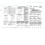
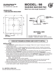
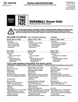
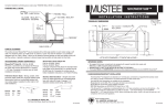
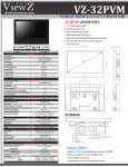
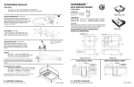
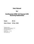
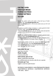
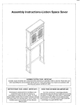
ROUGH-IN:
E.L. Mustee & Sons, Inc.
5431 West 164th St.
Brook Park, OH 44142
NOTE: DIMENSIONS SHOWN ARE FOR REFERENCE ONLY! MEASURE ACTUAL SHOWER
FLOOR BEFORE BEGINNING "ROUGH-IN"
SHOWER FLOOR
*Indicates model made with Durastone™ and PN-42.317A • DRAIN ASSEMBLY
SQUARE - RECTANGULAR MODELS
MODEL NO.
3232M
NOM SIZE
32" x 32"
(812.8) x (812.8)
3248M
32" x 48"
3248SD* (812.8) x (1219.2)
3254M
32" x 54"
(812.8) x (1371.6)
3260M
32" x 60"
(812.8) x (1524)
3434M*
34" x 34"
(863.6) x (863.6)
3442M
34" x 42"
(863.6) x (1066.8)
3448M
34" x 48"
3448SD* (863.6) x (1219.2)
3454M
34" x 54"
(863.6) x (1371.6)
3460M
34" x 60"
(863.6) x (1524)
3636M
36" x 36"
(914.4) x (914.4)
4236M
42" x 36"
(1066.8) x (914.4)
4242M
42" x 42"
(1066.8) x (1066.8)
Slip resistant STARBURST ®
floor pattern
DOUBLE THRESHOLD - CORNER MODELS
A
32"
(812.8)
48"
(1219.2)
54"
(1371.6)
60"
(1524)
34"
(863.6)
42"
(1066.8)
48"
(1219.2)
54"
(1371.6)
60"
(1524)
36"
(914.4)
36"
(914.4)
42"
(1066.8)
B
32"
(812.8)
32"
(812.8)
32"
(812.8)
32"
(812.8)
34"
(863.6)
34"
(863.6)
34"
(863.6)
34"
(863.6)
34"
(863.6)
36"
(914.4)
42"
(1066.8)
42"
(1066.8)
C
16"
(406.4)
16"
(406.4)
16"
(406.4)
16"
(406.4)
17"
(431.8)
17"
(431.8)
17"
(431.8)
17"
(431.8)
17"
(431.8)
18"
(457.2)
21"
(533.4)
21"
(533.4)
D
16"
(406.4)
24"
(609.6)
27"
(685.8)
30"
(762)
17"
(431.8)
21"
(533.4)
24"
(609.6)
27"
(685.8)
30"
(762)
18"
(457.2)
18"
(457.2)
21"
(533.4)
Email: [email protected]
Web: www.mustee.com
INSTALLATION INSTRUCTIONS
SQUARE / RECTANGULAR
NOTE: Dimensions in Parenthesis ( ) are metric equivalents in millimeters (mm)
DOUBLE THRESHOLD
(CORNER)
MODEL NO.
3434DTM*
3636DTM
NOM SIZE
34" x 34"
(863.6) x (863.6)
36" x 36"
(914.4) x (914.4)
A
34"
(863.6)
36"
(914.4)
B
34"
(863.6)
36"
(914.4)
C
17"
(431.8)
18"
(457.2)
D
17"
(431.8)
18"
(457.2)
File Numbers:
#1453 • Shower floor
#1251 • Strainer
#1635 • Drain Assembly
NOTE: Dimensions in Parenthesis ( ) are metric equivalents in millimeters (mm)
Slip resistant STARBURST ®
floor pattern
NEO-ANGLE THRESHOLD - CORNER MODELS
MODEL NO.
3636CM
3838CM
4242CM
NEO-ANGLE THRESHOLD
(CORNER)
Warnock Hersey® Listed—
CSA Test Standards:
Shower Floor — #B45.0
and #B45.5
IMPORTANT NOTES:
NOM SIZE
36" x 36"
(914.4) x (914.4)
38" x 38"
(965.2) x (965.2)
42" x 42"
(1066.8) x (1066.8)
A
36"
(914.4)
38"
(965.2)
42"
(1066.8)
B
36"
(914.4)
38"
(965.2)
42"
(1066.8)
C
12"
(304.8)
12"
(304.8)
12"
(304.8)
D
12"
(304.8)
12"
(304.8)
12"
(304.8)
E
18"
(457.2)
20"
(508)
24"
(609.6)
• We suggest that shower compartments be equipped with support handrails that comply with
ANSI-117.1-1986 Consumer Safety requirements
• DO NOT USE WITH "FREE STANDING SHOWER CABINETS, FOR "BUILT-IN" INSTALLATION ONLY
• SHOWER FLOORS ARE NOT TO BE INSTALLED IN FRONT OF DRYWALL!
• Thoroughly READ and UNDERSTAND instructions before beginning installation of your
MUSTEE Shower Floor
NOTE: Dimensions in Parenthesis ( ) are metric equivalents in millimeters (mm)
Quality Plumbing Products
E.L. MUSTEE & SONS, INC.
®
Slip resistant STARBURST ®
floor pattern
SI-190 (8•07)
4
5431 West 164th Street • Brook Park, Ohio 44142
SI-190 (8•07)
ROUGH-IN PREPARATION
IMPORTANT: "ROUGH-IN" dimensions are provided for reference only! Measure actual Shower
Floor and check local building code requirements before constructing alcove.
"SOLID SURFACE" WALL NOTE
MUSTEE '700' SERIES FIBERGLASS
SHOWERWALL INSTALLATION DETAIL
FOR INSTALLATION OF "SOLID SURFACE" WALL
PANELS – IT IS RECOMMENDED THAT THE
UNDERSIDE OF THE TILE FLANGES BE REINFORCED
AS SHOWN IN SKETCH.
NOTE: If using MUSTEE 700 Series Fiberglass Showerwalls, review instructions provided with
wall unit before framing alcove. (See detail shown below for typical installation.)
1.
Refer to "ROUGH-IN" dimensions and determine location of Shower Floor.
2.
Next, prepare SUB-FLOOR in Shower Floor area as follows:
Wood/Joist Floor:
Sub-floor must be min. 3/4" construction grade sheathing (CDX). Make sure
sub-floor is securely fastened to floor joists throughout alcove area with either
"Drywall"/Bugle Head screws (2-1/2" min.) or nails (rec. 8d Spiral Flooring Nails).
Make sure any "creaking or squeaks" have been eliminated by walking around
alcove area before proceeding.
Concrete/Cement Slab Floor:
Prepare surface in alcove area so that floor is level and sound.
3.
4.
Provide a 5" (inch) square opening in sub-floor or slab to accommodate Shower Floor drain body.
(Slab installation requires opening to be min. 2-1/4" deep). NOTE: If using a hole saw to cut floor
opening, you MUST use a 4-1/2" diameter (minimum) hole saw. Opening to be centered about
drain centerlines as specified in "ROUGH-IN" dimensions. Drain connection requires 2" (inch)
DWV pipe. Top of drain pipe must be even with top of sub-floor or slab.
SECTIONAL VIEW
Finally, we recommend that Shower Floor be installed on a bed of 30 lb. roofing felt or
equivalent to compensate for any inconsistencies in sub-floor or slab. (Gypsum cement or
panel/ floor adhesive could also be used for this purpose.)
CAULK THIS AREA
SHOWER FLOOR INSTALLATION
5.
Check Shower Floor carefully making sure it is not damaged.
6.
Set Shower Floor into place. Level Shower Floor in both directions.
NOTE: Place level along top edge of tile flanges - do not use floor area which is tapered for
water drainage!
7.
Shower w/Integral Drain Body
Apply a lubricant of some type (liquid soap works well) to the inside and outside of the Drain
Seal† prior to installation. Place Drain Seal over pipe and tamp into place using a hammer and 1/4" (inch) dia. blunt rod or dowel. (Hint: 1/4" dia. bolt approx. 6" long works well as a tamping
tool.) Make sure top of Drain Seal is even with top of 2" (inch) waste pipe and in full compliance
with local code requirements pertaining to below floor waste connectors. (see Sectional View)
8.
SUPPORT FRAMING (OPTIONAL) REF.
"SOLID SURFACE" WALL
DRAIN DETAIL PN.42.317A
† AN OPTIONAL DRAIN SEAL:
PN.- 42.320, IS AVAILABLE FOR 2" COPPER (DWV)
PN.- 42.321, IS AVAILABLE FOR 2" SOIL PIPE (SW)
SANITARY DRAIN/WASTE CONNECTIONS
FOR REPLACEMENT DRAIN ASSEMBLY - COMPLETE
ORDER PN. 42.317A
Snap Strainer‡ into place.
CAUTION:
(†) Optional DRAIN SEALS are available:
(‡) Optional STRAINERS are available:
PN.- 32.403 - 2" SOIL PIPE/CAST IRON-SERVICE WT. (NO HUB)
SANITARY DRAIN/WASTE CONNECTIONS
PN.- 32.404 - 2" COPPER-DWV, TYPE K,L or M
PN.- 34.305 - POLISHED BRASS
PN.- 34.301 - POLISHED STAINLESS STEEL
PN.- 42.323 - MOLDED ('BONE')
PN.- 42.324 - MOLDED
('BISCUIT')
2
DO NOT USE ANY PUTTY OR THREAD SEALING COMPOUND
UNDER FLANGE OR ON THREADS OF DRAIN BODY
- FAILURE AND LEAKAGE MAY RESULT!!!
DO NOT OVERTIGHTEN LOCKNUT - HAND TIGHTEN, THEN
WRENCH ADDITIONAL 3/4 TURN - MAXIMUM.
3