Transcript
installation
For Models:
Tools:
813-971, 813-973, 813-912, 813-913, 813-684, 813-459
813-579, 813-445, 559-319, 566-731, 323-936, 181-265
323-867, 332-120, 348-485, 418-609, 291-226
H125 x W120mm
Maintenance
Your new bathroom faucet is designed for
years of trouble-free performance.
• Adjustable wrench
• Hex Wrench
• Groove joint plier
• Plumber’s putty
• Pipe tape
• Phillips screwdriver
1
Safety Tips
Important points
• If you use soldering for the installation of the faucet, the
seats cartridges and washers will have to be removed
before using flame. Otherwise, warranty will be void on
these parts
• Protect your eyes with safety glasses when cutting or
soldering water supply line
• Cover your drain to avoid loosing parts
Prior to beginning installation, turn off the cold and hot water
lines and open the old faucet to release build-up pressure.
When installing your new faucet, turn the connector nuts fingertight, then use one wrench to anchor the fitting and a second
wrench to tighten the nut one additional turn. Connections that
are too tight will reduce the integrity of the system.
Wrap all threaded connections with Teflon tape available at
your local hardware or plumbing supply store. Always wrap in
a clockwise direction.
2
3A
1 888 328-2383 USA
8 a.m. to 8 p.m. EST Monday-Friday
9 a.m. to 5 p.m. EST Saturday & Sunday
PMS4495
lines: Slip coupling nut behind ball-nose of flexible supply
tube. Ball nose coupling will go partially into IPS shank
or fitting. Tighten coupling nut (DO NOT OVER TIGHTEN).
Install opposite end according to manufacturer’s instructions for both tubes.
4
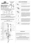
Place new faucet in position on sink. From under sink,
thread nuts onto faucet. Tighten nuts.
1
Need help?
For additional assistance or service call:
BLACK
Ball Nose Flexible Supplies: If you are using ball-nose
3B (B)
flexible supplies to connect the faucet to water supply
Shut off water supply. Remove old faucet. Clean sink surface in preparation for new faucet.
(A) Stainless Steel Braided Faucet Supply Tubes: This is
the simplest of all installations. If you are using stainless
steel braided faucet supply tubes, this faucet requires one
end of the supply tube to have a 1/2" female IPS connection. The other end of this supply tube must match
the thread on the water supply fittings or shut off valve
under your sink. Once you have identified the required
tube, carefully follow the manufacturer’s installations
instructions for each tube.
2
3
Place a ring of putty around drain opening of sink. Insert
threaded end of drain body up through drain hole and
attach flange to body with ball rod pointing to rear of
sink.
4
Thread locknut from underside of sink until rubber washer seats securely inside opening of sink. Tighten locknut.
Wipe excess putty. If model has plastic wing nut, tighten
securely. If nut brass, tighten with wrench.
559-319
566-731
Important: After installation is completed, remove aerator. Turn on water supply and allow both hot and cold
water to run for at least one minute each. While water is
running, check for leaks. Replace aerator. Tighten nuts
slightly to stop minor leaks. If problems persist, refer to
trouble shooting chart.
ADJUSTING LIFT ROD
Steps 3B-6
Handle
Adjust lift rod function by adjusting location of thumb screw along the lift rod or
by adjusting the hole in which ball rod
goes through strap.
Be sure to leave enough space between
lift rod knob and faucet spout when rod
is down.
Set screw
559-319
566-731
Aerator
5
Place one end of spring clip on end of ball rod. Insert rod
across and through hole in lift rod strap. Secure other
end.
Remove flange from pop up main body. Leave large
black washer (not included with plastic pop ups) and nut
on drain body.(For 559-319 & 556-731: Remove nut
and metal washer and black rubber washer fram flange.
Leave white rubber washer on the flange.)
813-912
813-913
6
Unscrew the nut from the pop up body and take off the
spring clip from the ball rod (please note: retain the
white packing ring on the ball rod), and place the nut in
the ball rod. lnsert the ball rod into the side hole of drain,
slide the nut on and tighten securely.
813-459
332-120
348-485
Washer
PROBLEM
Leaks underneath handle.
CAUSE
Retainer nut has come loose or Oring on cartridge is dirty or twisted.
ACTION
1. Move the handle to the off position. Unscrew the handle screw and
remove the handle (Diagram A).
2. Tighten the retainer nut by turning it clockwise (Diagram B). Move the
cartridge stem to the on position. The leak should stop draining out
from around the cartridge stem.
3. If the leak does not stop, shut off the water supply. Remove the retainer nut by turning it counter clockwise. Lift out the cartridge valve
(Diagram C). Inspect the larger Oring on the cartridge bonnet and the
smaller Oring on the cartridge stem. Remove any debris from the
Orings. If either Oring is twisted, straighten it out. If either Oring is
damaged, replace it.
4. Position the cartridge back to the faucet body (Diagram D). Make sure
the wings on the two sides of the cartridge bonnet fit into the cuts on
the two sides of the faucet body. Tightly screw the retainer nut onto
the faucet body.
5. Re-install the handle.
PROBLEM Water does not completely shut off.
CAUSE Rubber valve seat is dirty, stuck or broken.
ACTION
1. Shut off the cold water supply. If leakage stops, the problem is on the
cold side. If leakage continues, the problem is on the hot side. Shut off
the hot water supply to determine if both the cold and hot sides have a problem.
323-936/181-265
323-867
Insert bottom of lift rod into hole at top of pop-up strap.
Tighten with thumb screw.
2. Remove the handle on the problem side. Loosen the retainer nut by
turning it counter-clockwise (Diagram E). Lift out the cartridge assembly.
3. Inspect the larger O-ring on the cartridge bonnet and the smaller O-ring
on the cartridge stem. Remove any debris from the O-rings. If either Oring is twisted, straighten it out. If either O-ring is damaged, replace it.
4. Re-position the cartridge back to the faucet body. Make sure that the
wings on the two sides of the cartridge bonnet fit well into the cuts on
the two sides of the faucet body (Diagram F). Tightly screw the retainer nut onto the faucet body.
5. Re-install the handle.
PROBLEM Faucet leaks around aerator.
CAUSE Aerator incorrectly fitted.
ACTION
1. Unscrew the aerator by turning it clockwise (Diagram G). Inspect the
black rubber packing inside the aerator. The rubber packing should be
flat.
2. Screw the aerator onto the spout end and tighten.
PROBLEM Improper water pattern.
CAUSE Aerator dirty or small parts inside aerator improperly installed.
ACTION
1. Remove the aerator from the spout end by turning it clockwise.
2. Gently flush the small parts inside the aerator to clear away any debris.
3. Re-install the small parts as shown in the exploded diagram (Diagram
H). Metal screens must be flat and plastic supporter must be straight.
4. Screw the aerator onto the spout end and tighten.
A
B
C
D
E
F
G
H
Lock Nut
Coupling Nut
813-445
Steps 1-3A
Troubleshooting
Cartridge
Installation - Pop-Up drain
All installations can vary depending on how your previous faucet was installed. Necessary supplies to install
your faucet are not all included; however they are available wherever plumbing supplies are sold. When
choosing your installation supplies, make sure they are IAPMO and/or CSA approved products.
What you need to know
Installation
Installation
Keep it looking new by cleaning it periodically with a soft
cloth. Avoid abrasive cleaners, steel wool and harsh chemicals
as these will dull the finish and void your warranty.
Things You May Need
813-971 A
Installation
Preparation/Assembly
Steps 7-10
813-579
813-684
418-609
Parts diagram