1
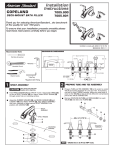
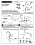
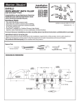
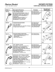
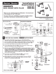
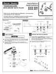
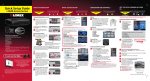
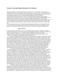
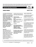
Installation
Instructions
GREEN TEA
7010.900
7010.901
DECK-MOUNT BATH FILLER
Thank you for selecting American-Standard...the benchmark
of fine quality for over 100 years.
To ensure that your installation proceeds smoothly--please
read these instructions carefully before you begin.
Certified to comply with ANSI A112.18.1M
M968595 Rev.1.3
ROUGHING-IN DIMENSIONS
Recommended Tools
ADJ. 6-1/2 TO 12
10-5/8"
Flat Blade Screwdriver
7-7/8"
(200mm)
2-1/8"
5-5/16"
*Wrench
MOUNTING
SURFACE
Adjustable Wrench
3-3/4"
1-1/4
MAX.
1-1/8 DIA.
2-9/16"
2-1/16
DIA.
2-1/16"
DIA.
3"
1-1/2 MAX.
3
8-1/16"
1-3/16 DIA.
Channel Locks
3/4-14 MALE
N.P.T. INLETS
*Hex key
2
SPOUT ASSEMBLY
CAUTION
12 MAX
1-1/16 DIA.
*Supplied with Fitting
1
(C)
(H)
Turn off hot and cold water
supplies before beginning.
Install RING WASHER (1) into SPOUT recess. Check that O-RING (2)
on end of SPOUT SHANK (3) is in place. Insert SPOUT SHANK (3)
through center hole on mounting surface.
Assemble RUBBER WASHER (4) and BRASS WASHER (5) and
LOCKNUT (6) onto SPOUT SHANK (3). Align SPOUT ASSEMBLY
and from underside of ledge secure SPOUT ASSEMBLY into
position with LOCKNUT (6).
PREPARE TUBE AND TEE ASSEMBLY
Prepare TUBE and TEE ASSEMBLY (1) to fit center to center
VALVE (2) location (between 6-1/2" and 12"). If necessary,
cut and/or bend TUBING carefully. Make sure tube bend is
close to the TEE (1) so that it will not effect the compression
joint at the VALVE CONNECTION.
Remove COUPLING NUT (3) and FERRULE (4) from each
VALVE (2) and slide onto TUBING (5).
4
3
1
5
SPOUT
ASSEMBLY
3
4
ADJ. 6-1/2 TO 12
SPOUT RECESS
3
1
2
MOUNTING
SURFACE
MOUNTING
SURFACE
2
4
5
6
NOTE
VALVE inlet is 3/4-inch NPT male.
3
VALVE ASSEMBLY
9
10
Install LOCKNUTS (1) and RUBBER WASHERS (2) onto valve shanks.
Push TUBING (3) ends into VALVE (4) side outlets. Insert VALVES (4)
into mounting holes from underside of ledge.
11
9
Press TEE (5) onto SPOUT SHANK (6) making certain that the O-RING (7) is
properly seated on SHANK (6). Push COUPLING (8 or 8a) into TEE (5) and
attach to SPOUT SHANK (6) and tighten. For 7005.901 use a 10 mm
(3/8") hex key.
Thread of VALVE BODY (4) should extend at least 5/16 inch above
MOUNTING SURFACE (11). If necessary, adjust LOCKNUT (1).
10
7
Place RUBBER RING (10) into ESCUTCHEON ADAPTERS (9) and thread onto
valves until snug against internal stop.
Tighten LOCKNUT (1) to secure VALVE (4) position.
12
HOT
Slide FERRULE (12) and COUPLING NUT (13) to outlet of VALVE (4) and tighten
COUPLING NUT (13) firmly.
4
3
Connect HOT water supply to inlet of left VALVE and COLD water supply to inlet of
right VALVE using appropriate connector.
5/16'' MIN.
4
8
7
11
2
6
13
12
5
8
8a
MOUNTING
SURFACE
MOUNTING
SURFACE
13
COLD
FOR FITTING
LESS SPRAY
1
4
INSTALL HANDLES
Push ADAPTER (1) on VALVE STEM (2), so that the hole of the
ADAPTER (1) without a spline is facing up. Fig. A. Tighten
STEM SCREW (3) to secure ADAPTER (1).
4
4a
Find correct position of LEVER HANDLE ASSEMBLY (4) by adjusting
male teeth on ADAPTER (1) to female teeth in HANDLE (4). Push
LEVER HANDLE ASSEMBLY (4) down onto ADAPTER (1).
Thread base of LEVER HANDLE ASSEMBLY (4a) onto DECK
ADAPTER (5) until snug against mounting surface.
TOP
1
3
2
Fig. A.
5
SPLINE END DOWN
5
SERVICE
To change direction of handle:
Turn valve to OFF position
Thread HANDLE BASE (1a) counter clock-wise until loose.
1
Pull HANDLE (1) “UP” firmly to release from ADAPTER (2).
Remove SPRING CLIP (3). Lift STOP WASHER (4), turn 90˚
and replace. Replace SPRING CLIP (3).
1a
re
m ov
e
Re-install HANDLE ASSEMBLY (1).
If spout drips, operate handles several times from OFF to ON position.
Do not force - handles turn only 90˚.
90˚
ll
insta
2
4
3
2
M968595 Rev.1.3
6
HANDSHOWER INSTALLATION
11
(FOR MODEL 7010.901 ONLY)
9
Drop SPRAY ESCUTCHEON (1) through the fourth hole of the tub ledge (12" max from SPOUT
center) with SPRAY ESCUTCHEON (1) directed towards tub center. Be sure RUBBER RING (2)
is properly seated in ESCUTCHEON (1). Install RUBBER WASHER (3) and LOCKNUT (4) from
underside of ledge.
Secure SPRAY ESCUTCHEON (1) by tightening LOCKNUT (4).
6
Add SEAL WASHER (5) and connect HOSE (10) to outlet nipple
at the bottom of TEE (7). Tighten firmly.
Slip SHOWER HOSE (8) with COUPLING NUT through SPRAY
HOLDER (6) and ESCUTCHEON (1). ( Note: SPRAY HOLDER (6)
must be separate from ESCUTCHEON (1) to get HOSE (8)
thrrough ESCUTCHEON (1).] Install SEAL (9) and connect both
HOSES (8) and (10). INSTALL second SEAL (9) and connect
HAND SHOWER (11) to SPRAY HOSE (8).
1
2
3
7
5
4
10
NOTE
7
8
When not in use, HANDSHOWER should be seated
in the HOLDER.
9
MAKE WATER SUPPLY CONNECTIONS
Connect HOT water supply to LEFT INLET
UNION (1) and COLD water supply to
RIGHT INLET UNION (2). Pipe connections
are 3/4" NPT. Use sealant or Teflon tape
on pipe connections.
Do not solder directly to valve body.
7A
HAND
SHOWER
TRANSFER KNOB
TEST INSTALLED FAUCET
With HANDLES in OFF position, turn on
WATER SUPPLIES and check all connections
for leaks.
Operate both HANDLES to flush water lines
thoroughly.
Lift HAND SHOWER from HOLDER, direct spray
into tub. Lift TRANSFER KNOB to check HAND
SHOWER and HOSES for leaks.
COLD
2
3/4" NPT
HOT
1
3/4" X 3/4" NPT UNION
(NOT SUPPLIED)
3/4" NPT
IMPORTANT: It is strongly recommended that access be
provided for all enclosed mechanical parts to this system.
Turn handles "off" and replace HAND SHOWER.
8
Before the bathroom is completely finished, you may
want to remove spout, handshower, and handles to
avoid damage during construction.
2
To remove handles, reverse steps in section 4.
VIEW "A"
To remove SPOUT (1), proceed as follows:
Unthread LIFT ROD KNOB (2) to release it from the
TRANSFER ROD (8). Remove LIFT ROD KNOB (2). VIEW A.
Remove PLUG BUTTON (3) and remove SET SCREW (4)
using 4mm hex wrench supplied.
Lift SPOUT (1) off SHANK (5) carefully and remove RUBBER
RING (6).
Unthread SHANK SLEEVE (7) and remove from SHANK (5).
Reverse sequence to re-install SPOUT (1). Be sure RUBBER
RING (6) is properly seated in its recess at the base of the
SPOUT (1). Make certain SET SCREW (4) is properly aligned
and tight so that SPOUT (1) is locked in place.
8
3
1
6
FIG. 1
4
8
VIEW "A"
Hex wench
(supplied)
7
5
CARE INSTRUCTIONS:
DO: SIMPLY RINSE THE PRODUCT CLEAN WITH CLEAR WATER. DRY WITH A SOFT COTTON FLANNEL CLOTH.
DO NOT: DO NOT CLEAN THE PRODUCT WITH SOAPS, ACID, POLISH, ABRASIVES, HARSH CLEANERS, OR A
CLOTH WITH A COARSE SURFACE.
M968595 Rev.1.3