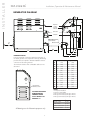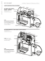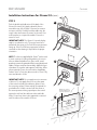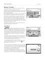
1
Installation, Operation and Maintenance Manual Steambath Generator Systems Residential Models: MS90E – MS400E and MSSUPER1E – 6E mr.steam ® Feel Good Inc.™ READ ME FIRST! ! WARNING As you follow these instructions, you will notice warning and caution symbols. This blocked information is important for the safe and efficient installation and operation of this generator. These are types of potential hazards that may occur during installation and operation: ! WARNING Indicates a potentially hazardous situation, which, if not avoided, could result in death or serious injury. ! CAUTION Indicates a potentially hazardous situation, which, if not avoided may result in minor or moderate injury or product damage. IMPORTANT NOTE: This highlights information that is especially relevant to a problemfree installation. All information in these instructions is based on the latest product information available at the time of publication. Sussman-Automatic Corporation reserves the right to make changes at any time without notice. When installing and using this electrical equipment, basic safety precautions should always be followed, including the following: IMPORTANT SAFETY INSTRUCTIONS 1. READ AND FOLLOW ALL INSTRUCTIONS 2. ! WARNING DO NOT permit children under the age of 16 to use this steambath. 3. ! WARNING Steam is hot and can cause injury or death if improperly used. Steam rooms contain steam and elevated temperatures. Please read and observe all warnings in this manual before installing or using a steam room. 4. ! WARNING To reduce the risk of injury: A. The wet surfaces of steam enclosures may be slippery. Use care when entering or leaving. B. The steam head is hot. DO NOT touch the steam head and avoid the steam near the steam head. C. Prolonged use of the steam system can raise excessively the internal human body temperature and impair the body’s ability to regulate its internal temperature (hyperthermia). Limit your use of steam to 10-15 minutes until you are certain of your body’s reaction. HYPERTHERMIA occurs when the internal temperature of the body reaches a level several degrees above the normal body temperature of 98.6° F. The symptoms of hyperthermia include an increase in the internal temperature of the body, dizziness, lethargy, drowsiness, and fainting. The effects of hyperthermia include: D. Excessive temperatures have a high potential for causing fetal damage during the early months of pregnancy. Pregnancy or possibly pregnant women should consult a physician regarding correct exposure. E. Obese persons and persons with a history of heart disease, low or high blood pressure, circulatory system problems, or diabetes should consult a physician before using a steambath. F. Persons using medication should consult a physician before using a steambath since some medication may induce drowsiness while other medications may affect heart rate, blood pressure and circulation. SAVE THESE INSTRUCTIONS a) Failure to perceive heat; b) Failure to recognize the need to exit the steambath; c) Unawareness of impending risk; d) Fetal damage in pregnant women; e) Physical inability to exit the steambath; and f) Unconsciousness. ! WARNING The use of alcohol, drugs, or medication can greatly increase the risk of hyperthermia. Designed, Engineered and Assembled in the #### USA PUR 100472A Rev 3.15 mr.steam ® Sussman-Automatic Corporation® [email protected] www.mrsteam.com 43-20 34th Street, Long Island City, NY 11101 9410 S. La Cienega Blvd. Inglewood CA 90301 TEL: TEL: 1 800 76 STEAM 1 800 72 STEAM FAX: 718 472 3256 FAX: 310 216 2944 RESIDENTIAL STEAMBATH GENERATOR SYSTEMS INSTALLATION, OPERATION MODEL _______________________________ & MAINTENANCE MANUAL MODELS: MS-90E, MS-150E, MS-225E, MS-400E, MS-SUPER 1E, MS-SUPER 2E, MS-SUPER 3E, MS-SUPER 4E, MS-SUPER 5E, MS-SUPER 6E TABLE OF CONTENTS Important Safety Instructions . . . . . . . . . . . . . Inside front cover Select Your Mr.Steam Model . . . . . . . . . . . . . . . . . . . . . . . . . . 2 Generator Specification Chart . . . . . . . . . . . . . . . . . . . . . . . . . 2 _______________________________________________________________________ INSTALLER SECTION Before Installing . . . . . . . . . . . . . . . . . . . . . . . . . . . . . . . . . . . 3 Steam Room Guidelines . . . . . . . . . . . . . . . . . . . . . . . . . . . . 3 Water Quality Information . . . . . . . . . . . . . . . . . . . . . . . . . . . 4 Locating the Steam Generator . . . . . . . . . . . . . . . . . . . . . . . 4 Typical Installation Instructions . . . . . . . . . . . . . . . . . . . . . . . 5 Installation: Plumbing, Water Supply, Drain, Steam Outlet Safety Valve, Drip Pan, AromaSteam . . . . . . . . . . 6 Steam Head Installation. . . . . . . . . . . . . . . . . . . . . . . . . . . . . 7 Steam Generator Dimensions . . . . . . . . . . . . . . . . . . . . . . . . 8 Electrical Specifications & Field Power Wiring . . . . . . . . . . . 9 Wiring Diagrams . . . . . . . . . . . . . . . . . . . . . . . . . . . . . . . 10-11 Optional Tandem Cable Diagram . . . . . . . . . . . . . . . . . . . . 11 Initial Start-Up & Checkout . . . . . . . . . . . . . . . . . . . . . . . . . 12 Optional & Accessary Equipment . . . . . . . . . . . . . . . . . . . . 12 Troubleshooting . . . . . . . . . . . . . . . . . . . . . . . . . . . . . . . . . . 12 System Status Codes . . . . . . . . . . . . . . . . . . . . . . . . . . . . . . 13 Liquid Level Control Board . . . . . . . . . . . . . . . . . . . . . . . . . 13 Optional AutoFlush System . . . . . . . . . . . . . . . . . . . . . . . . . 14 Optional Drip Pan . . . . . . . . . . . . . . . . . . . . . . . . . . . . . . . . 15 Optional Express Steam . . . . . . . . . . . . . . . . . . . . . . . . . . . 15 Parts Identification Diagrams. . . . . . . . . . . . . . . . . . . . . . . . 16 Replacement Parts List. . . . . . . . . . . . . . . . . . . . . . . . . . . . . 17 CONTROL INSTALLATION Before Installing . . . . . . . . . . . . . . . . . . . . . . . . . . . . . . . . . . 18 Control Rough-In . . . . . . . . . . . . . . . . . . . . . . . . . . . . . . . . . 18 _______________________________________________________________________ HOMEOWNER SECTION Important Safety Instructions. . . . . . . . . . . . . . . . . . . . . . . . 19 Setting Steam Bath Temperature & Duration . . . . . . . . . . . 20 Safety & Operating Info. . . . . . . . . . . . . . . . . . . . . . . . . . . . 20 Care Tips for Controls and Generator Maintenance . . . . . . 20 Using the AromaSteam Essential Oils . . . . . . . . . . . . . . . . . 21 Warranty. . . . . . . . . . . . . . . . . . . . . . . . . . . . . . . . . . . . . . . . 21 mr.steam ® Feel Good Inc. SERIAL NO. ___________________________ mr Installation, Operation & Maintenance Manual .steam __________________________________________________________________________ ® SELECT YOUR MR.STEAM ! WARNING In considering the purchase or use of this steambath system, please note that if you are pregnant, have a coronary condition, are in poor health, are being treated for any other medical condition, or are using medication or drugs, Mr.Steam recommends that you obtain the approval of a physician before use. For information about this product and safety issues, please call 1.800.76.STEAM Mr.Steam @ Your Fingertips: Start working smarter with Mr.Steam’s mobile sizing app, now available for the iPad®, iPod® and most smart phones. Visit mrsteam.com to size your generator automatically or go directly to: http://isizing.mrsteam.com IMPORTANT NOTES: For steam rooms constructed of acrylic or synthetic materials, select next lower-rated MS model. Materials of construction, room size and special design features such as large glass areas, all affect the steam generator model selection. 1. Measure length, width & height in feet of the steam/shower or tub/shower Multiply the Length ____ x Width_____ x Height _____ = ROOM VOLUME 2. Construction Materials: For natural stones: natural marble, stone, shale, glass block or concrete Add 110% For ceramic or porcelain tile on cement board or mortar bed Add 40% 3. Ceiling Height: For each foot above 8 feet The Mr.Steam Sizing Chart allows for up to 60 feet of insulated steam line from the MS generator to the steam room. If the 60 foot line is exceeded consult with factory. The steam generator control locations must be taken into account. A 30 foot cable is standard. Contact Mr.Steam to purchase an optional 60 ft. cable PN 103990-60 for iTempo and PN 104117-60 for iSteam Add 15% 4. Add all figures above to obtain the Total Room Volume required Compare your Room Volume to the Chart below and select the appropriate model. R E S I D E N T I A L S T E A M G E N E R AT O R S S P E C I F I C AT I O N C H A R T KW Amps (for 240v/1PH)† Wire Size‡ Total Adj. Room Vol. Water Usage Gallons†† MS90E 5 21 10 100 0.67 14½"L x 14¾"H x 6¾"D 30 MS150E 6 25 8 150 0.80 14½"L x 14¾"H x 6¾"D 30 MS225E 7.5 32 8 225 1.0 14½"L x 14¾"H x 6¾"D 30 MS400E 9 38 8 360 1.2 14½"L x 14¾"H x 6¾"D 30 MS SUPER 1E 10 42 8 475 1.4 17"L x 18½"H x 77⁄8"D 40 MS SUPER 2E 12 50 6 575 1.6 17"L x 18½"H x 77⁄8"D 40 MS SUPER 3E 15 63 4 675 2.0 17"L x 18½"H x 77⁄8"D 40 MS SUPER 4E 20 84 8 875 2.7 17"L x 18½"H x 77⁄8"D x 2 80 MS SUPER 5E 24 100 6 1075 3.2 17"L x 18½"H x 77⁄8"D x 2 80 MS SUPER 6E 30 125 4 1275 4.0 17"L x 18½"H x 77⁄8"D x 2 80 Model No. IMPORTANT NOTES: • Add C1 suffix to Model No. for 240V/1Ph; Add B1 suffix to Model No. for 208V/1Ph. • Models SUPER 1E-6E must use iTempo/Plus™ control. • All Mr.Steam MS Models are cULus Listed and CE approved. Dimensions* Shipping Wt. (lbs)** *Dimensions are for generator only, without AutoFlush® or plumbing features. **Shipping weight and pricing are for generator only, without control or steamhead. †† Water usage based on 20 minutes of operation. NOTES: All MS Generators available in 240v/1PH, 208v/1PH and other voltages/phases. † Amps are for 240/1PH rated units. ‡Wire size (AWG) based on minimum 90˚C rated THHN copper conductors. Refer to the National Electrical Code for other types of conductors. See Mr. Steam® Installation and Operation Manual for complete dimensional and installation information. MS SUPER 4E includes two MS SUPER 1E steam generators, and require one iTempo/Plus™ Control, and two matching steamheads. MS SUPER 5E includes two MS SUPER 2E steam generators, and require one iTempo/Plus™ Control, and two matching steamheads. MS SUPER 6E includes two MS SUPER 3E steam generators, and require one iTempo/Plus™ Control, and two matching steamheads. 2 ® BEFORE INSTALLING the steambath room. Pay particular attention to room volume and construction. If any questions, please refer to Mr. Steam sizing and selection guide on page 2. Carefully inspect the Steam Generator and packaging for shipping damage. In the event of shipping damage, please contact the carrier for claim information. Our customer service department can assist you with any missing or damaged parts. 3. Marble or glass walls or ceilings. “ENLARGE” the room’s size, requiring a generator larger than one based only on the room’s cubic foot (L x H x W) volume. Read these instructions before installation or service. Although this MS steambath generator has been fully qualified for shipment by Mr.Steam®, the following must be reviewed for proper, safe and enjoyable steam bathing: 4. The physical size of the unit, clearance for plumbing servicing, and its distance from the steam room must all be considered before final installation. 5. Consider any controls and accessories before initiating installation. Read the Installation and Operation Manual of all controls and accessories available at www.mrsteam.com technical downloads. 1. Verify that the model and accessories specifications are correct for the incoming line voltage. 2. Insure steambath generator has been correctly sized for STEAM ROOM GUIDELINES 1. Steam room must be completely enclosed, with full walls, door, floor and ceiling. 2. It is recommended that a gasketed door is used for steam containment. 3. ! WARNING To prevent slip and fall hazards non-skip strips must be installed on the steam room floor. 4. Check the suitability of any materials with the manufacturer. Walls and ceilings must be constructed of water-resistant, non-corrosive surface, such as tile, marble, molded acrylic, or other non-porous material. 5. The ceiling should be sloped to prevent dripping of condensate. ! WARNING The peel and stick warning label located in this manual is an essential part of providing a safe environment for steam room users. The peel and stick warning label must be applied to the wall of the shower or steam enclosure, at a point that is visible to all users. Failure to install this sticker may result in serious injury or death. The location where this owner's manual is kept shall be written in the space provided on the label using permanent ink. For a replacement warning label contact Mr.Steam customer service at 1-800-76-STEAM or [email protected] 6. Provide a floor drain. 7. No heating, venting or air conditioning devices should be installed inside the steam room. 8. Steam room tile construction information is available from the Tile Council of America, Inc. by purchasing the TCA Handbook for Ceramic Tile Installation. Tel. (864) 646-8453 or www.tileusa.com. 9. Windows that are part of the steam room should be double paned and tempered safety glass. 10. Limit steam room ceiling height to 8 feet. Exceeding 8 feet may require a higher-rated steam generator. Not Actual Size ! WARNING Never use damaged equipment, doing so may result in an inoperative or hazardous installation. • Discontinue use of the steam generator and control if the steam generator or control are damaged or otherwise not functioning properly. Doing so may result in an inoperative or hazardous installation • ELECTRICAL SHOCK HAZARD. Mr.Steam steam generators are connected to 240V line voltage and contain live electrical components. All installation and service to be performed by qualified and licensed electricians and plumbers only. Installation or service by unqualified persons or failure to use Mr. Steam parts may result in property damage or in a hazardous condition. • The MS series of steam generators are for residential use only. Commercial or other nonresidential applications void the warranty and may adversely affect product performance and may represent a safety hazard. ! CAUTION If acrylic, fiberglass or other non-heat resistant materials are used as part of the steam room enclosure. Consult with the material manufacture and see pg. 7, “Installing the Steamhead" for additional details. IMPORTANT NOTES: This document contains important safety, operation and maintenance information. Leave this document with the homeowner. Do not discard this document. The following general information should be used in conjunction with consultations with an architect, designer and contractor in determining factors necessary in providing a suitable and safe steam room. Mr.Steam steam generators are intended to be operated with Mr.Steam iSteam®, iTempo/Plus™, iTempo™ Home Wizard™ and iGenie® controls only, and are to be installed strictly in accordance with the specific instructions contained in this manual and as supplied in the manuals provided with the controls or accessories. 3 I N S TA L L E R mr Installation, Operation & Maintenance Manual .steam __________________________________________________________________________ I N S TA L L E R mr Installation, Operation & Maintenance Manual .steam __________________________________________________________________________ ® WATER QUALITY INFORMATION For optimum results, the water supply should be tested prior RECOMMENDED FEEDWATER QUALITY Hardness, ppm 8 – 85 (~0.5 – 5 gpg) P-Alkalinity, ppm 85 – 410 (~5 – 24 gpg) T. Alkalinity, ppm 200 – 500 (~7 – 0 gpg) pH (strength of alkalinity) 8.0 – 11.4 to installation. If the mineral content exceeds the following recommended limits, various external treatment processes are recommended to correct the problem. NOTE: An analysis of the on-site water must be made by a recognized and reliable water treatment company to ascertain the existing condition and treatment required. Poor water quality can affect efficiency or result in steam generator damage. Water contains impurities in solution and suspension. These impurities concentrate in the generator. The concentration of these impurities increases as more feedwater is introduced into the generator and steam is produced. If the suspended solids are allowed to concentrate beyond certain limits, a deposit or “scale” will form on the generator internal surfaces. This deposit can interfere with the proper generator operation and cause generator failure. The concentration of these impurities is generally controlled by the water quality and by periodic draining of the generator. Every 2 months, or more often in “hard” water areas, the manual drain valve should be opened fully flushing out accumulated materials, salts and other particles which are natural by-products of boiling water. The optional AutoFlush System feature automatically drains the Mr.Steam® generator following each use. A time delay allows the water to cool down (about two hours) before it drains by gravity for a safe and gentle operation. LOCATING THE STEAM GENERATOR Select a location as near as practical to the steam room. Typical locations include: closet, vanity cabinet, heated attic or basement. NOTE: The standard length of the cable for connecting the control to the steam generator is 30 feet. The steam generator and control must be located accordingly. A 60 foot cable is available as a special order part for eTempo and iTempo, PN 103990-60 for iTempo and PN 104117-60 for iSteam. IMPORTANT NOTE: The control cable should be run in a dedicated 1" conduit to facilitate installation and service. ! WARNING DO NOT route iSteam, iTempo/Plus, iTempo, HomeWizard or iGenie control wiring inside conduit together with power lines or close to hot water or steam piping. Doing so may result in an inoperative or hazardous installation. ! WARNINGS (Items 1-4) Insure the steam generator is properly secured and level when mounting with keyhole slots to prevent damage to the steam generator. 7. Install steambath generator in an upright position only to prevent damage to the generator. 1. DO NOT install steambath generator inside steam room, a shock hazard will occur 2. DO NOT install steambath generator outdoors or wherever environmental conditions may result in a shock hazard or affect performance of the generator. 3. To prevent damage to the steam generator or a fire hazard DO NOT install steambath generator near flammable or corrosive materials or chemicals such as gasoline, paint thinners, or the like. Installation in areas having high concentrations of chlorine (such as pool equipment room) must be avoided. 4. Burn Hazard. Steam line, safety valve, drain valve and plumbing become hot during operation and remain hot after shutdown for a period of time. Provide appropriate protection, including insulating plumbing lines. Avoid plumbing runs and steamhead locations that can come in contact with bathers. IMPORTANT NOTES: (Items 8-11) 8. Install anti-water hammer device as necessary. 9. Provide a minimum of (12) inches at both ends and top of the steam generator or as required for servicing. See page 8. 10. Provide unions as required to facilitate installation and disconnection of piping. 11. Mr.Steam controls can be located inside the steam room or on the outside of the steam room. See the Control Installation Manual for your specific control package for specific details. 12. The MS series of steam generators are for residential use only. Commercial or other nonresidential applications void the warranty and may adversely affect product performance and may represent a safety hazard. ! CAUTIONS (Items 5-7) 5. DO NOT install steambath generator or plumbing lines in unheated attic or any locations where water could freeze and cause pipes to rupture and cause property damage. 6. Install steambath generator on a solid and level surface. Keyhole slots are provided for wall mounting. NOTE: Mr.Steam Generators (inclusive of the iTempo™ and iSteam series Controls) are CE and UL listed. ! WARNING Suitable for operation in ambient not exceeding 45 °C (113˚ F) 4 ® TYPICAL MR.STEAM INSTALLATION ! CAUTION The control features an integral temperature sensor. Locate the control in a location representative of the desired steambathing temperatures. Do not locate the control above or near the steam head or direct steam emissions. NOTE: Drawings for illustrative purposes only. Consult with qualified designer, architect or contractor for steam room construction details. iSteam®, iTempo™ or iTempo/Plus™ Control Refer to Control Installation Manual for installation information Provide unions as required to facilitate installation and disconnect of piping Control cable run in 1” conduit (located behind the wall) Field installed water supply line Field installed power supply Steam Generator Drain Valve must be closed when the optional AutoFlush is not installed Steam Head (shown with optional acrylic shield) See page 7 for Steam Head Installation information Field installed steam supply pipe ! CAUTION To avoid unintentional steambath operation, do not locate the control where other controls, accessories, shower heads, valves, body sprays or similar within the shower could cause confusion or interfere with the Mr.Steam control’s intended use and function. When installing the optional AromaSteam, install a downward facing 90-degree T in the steam supply line. See the AromaSteam Installation Manual for complete information. TYPICAL INSTALLATION INSTRUCTIONS FOR MODELS MS SUPER 4E, 5E & 6E (shown with optional AutoFlush) 1. Install each steam generator as in a single installation. Install generators as close as practical to each other, not exceeding 10 feet. The interconnecting cable length is 12 feet. 2. ! WARNING Shock Hazard. Power must be disconnected at the main electrical supply. Remove steam generator covers. Retain screws and covers for reuse. Primary Unit Power Supply 3. Connect the iSteam® or iTempo/Plus™ control to either unit as per the Installation Manual supplied with each control. iSteam or iTempo/Plus Control Interconnecting Cable PN 103904 Control Cable 4. Remove one knock-out on each generator as shown. Insert the ends of interconnecting cable provided (PN 103904) through the knock-outs as shown in diagram. Connect each end to the printed circuit board connector labeled "TANDEM" as shown. Water Feed Line 5. Prevent the interconnecting cable from contacting hot surfaces such as steam outlet, safety valve and the like. Steam Heads shown with optional acrylic shields 6. Connect separate plumbing and power supplies for each unit. Replace covers with cover screws. 7. Provide unions as required to facilitate installation and disconnection of piping Printed Circuit Board Component shown enlarged for illustrative purpose. Secondary Unit Optional AutoFlush®, see AutoFlush Installation page 14 NOTE: The secondary unit will de-energize when the steam room reaches steambathing temperature resulting in a more gentle and energy efficient operation. 5 All drawings are for illustrative purposes only I N S TA L L E R mr Installation, Operation & Maintenance Manual .steam __________________________________________________________________________ I N S TA L L E R mr Installation, Operation & Maintenance Manual .steam __________________________________________________________________________ ® INSTALLATION PLUMBING All plumbing shall be performed by a qualified licensed plumber and in accordance with applicable National and local codes. 1. Use unions on all pipe connections. 2. Use only brass piping or copper tubing as permitted by codes. 3. DO NOT use black, galvanized, PVC pipe or PEX. WAT E R S U P P LY ( 3 ⁄8 " N P T ) 1. Connect to cold water line. 2. Provide a shut off valve in the water supply line upstream of the steambath generator. 3. DO NOT overheat inlet solenoid valve with solder connections. Overheating will damage parts. 4. Flush inlet water line thoroughly before making connection to unit. 5. Strainer recommended upstream of feed water connection. 6. For best performance water pressure should be 15 to 20 psig. Reduce pressure as required. 7. Provide anti-water hammer device as required. 8. Install an approved backflow preventer as required by local codes. D R A I N ( 1 ⁄2 " N P T ) ! CAUTION The drain from the generator should not share an undersink trap, unless the generator is mounted higher than the sink to prevent damage to the generator if the drain backs up. NOTE: A drain valve is provided to facilitate servicing. Provide a drain line connection from steambath generator drain valve according to National and local Codes. Check local plumbing code for receptor, trap and vent requirements. Do not connect Drain line and Safety Valve line together. Unit drains by gravity. DO NOT connect the drain valve to the steam line S T E A M O U T L E T ( 1 ⁄2 " N P T ) 1. DO NOT install any valve in steam line. Flow of steam must be unobstructed. 2. Use 1/2-inch brass pipe or copper tubing from unit to steam head as permitted by codes. 3. Insulate steam line using pipe insulation rated 212° F or higher. 4. Pitch steam line 1/4" per foot towards steam head or steam generator to avoid valleys and trapping of condensate. NOTE: Running the steam line down and then up will create a steam trap blocking the flow of steam. NOTE: A 1.5" hole in the steam room is required to mount the steamhead. S A F E T Y VA LV E ( 3 ⁄4 " N P T ) Where permitted by local codes, provide an outlet plumbing connection for safety valve. ! WARNING To insure proper and automatic safety valve operation: DO NOT connect a shut off valve or a plug at safety valve outlet. DO NOT connect a shut off valve or any obstruction in steam supply pipe. DO NOT connect the safety-valve output into the steam line. D R I P PA N Mr. Steam strongly recommends the use of a drip pan in the unlikely event of a plumbing leak. Check local plumbing codes for receptor, trap and vent requirements. Drip pans drain by gravity. The drip pan is equipped with an integral 3/4" fitting. See page 15 for additional drip pan installation information . AROMASTEAM If the optional AromaSteam Electronic Oil Delivery System (PN: MS AROMA) is to be installed, a 90 degree T plumbing fitting must be installed at a designated location on the steam outlet line. See the Mr.Steam AromaSteam Operation and Instruction Manual (PN: 100402) for installation information before the steam line is installed at the technical downloads section of www.mrsteam.com 6 ® INSTALLING THE ROUND OR SQUARE AROMASTEAM STEAMHEAD (1⁄2" NPT) 1/8" minimum clearance required when Acrylic Shield is used. NOTE: A 1 ⁄2" clearance hole around the steam pipe is needed to mount the steamhead. STEP 1 Locate steam head 6-12 inches above floor, except for: 1. Tub/shower enclosures, install 6 inches above tub top edge. 2. For enclosures with acrylic or other non-heat resistant flooring install Acrylic Shield Part Number MS-103938. STEP 2 Install steamhead with the oil well facing up as shown. Hand tightening is sufficient when teflon or equal pipe thread sealing compound is used. See installation instructions provided with the Acrylic Shield. Use Teflon® or equal sealant on pipe threads 1 Steam Supply Pipe Apply with silicone or equal sealant as required for moisture seal. End of pipe to be recessed 1/4" (without Acrylic Shield) 1/8" (with Acrylic Shield) Oil Well STEP 3 1 Secure a bronze drop ear fitting to a header and run a ⁄2" copper steam line from the steam generator to the drop ear fitting. Install a temporary nipple (6" or longer) in the drop ear fitting to locate the steamhead after the wall is finished. STEP 3 STEP 4 After the wall has been finished, mark on the nipple where the surface of the wall is. Remove the nipple and measure the portion that was in the wall (the end to your mark). Subtract 1 ⁄4" from that dimension and select a brass nipple of that length to finish the installation. Drop Ear Fitting STEP 5 Wrap teflon tape around the threads of the new nipple and screw the nipple into the steamhead. Do not use wrenches or tools which would damage the steamhead's finish. Wrap teflon tape around the threads of the nipple and screw the nipple and steamhead assembly you just made into the drop ear fitting in the wall. The steamhead should be flush with the wall and the well must be facing up. STEP 4 __________________________________________________________ IMPORTANT NOTE: DO NOT disassemble steamhead. Mr.Steam’s steamhead is shipped fully assembled and requires no additional assembly. To preserve steam head finish, DO NOT use wrench or other tools to tighten. DO NOT use abrasive cleansers or chemicals. Use only water with mild soap and a non-abrasive sponge. ! CAUTION Because the steam head and direct steam emissions are very hot, locate the steam head where incidental contact by bather with the steam head or direct steam emission cannot occur. STEP 5 Consult with supplier of acrylic, fiberglass and other non-heat resistant enclosures for recommended steamhead location. Use Acrylic Shield PN MS-103938 (round) or PN MS-103938SQ (square). See instructions provided with steam shield. Steamhead (shown with optional acrylic shield) Locating Nipple All drawings are for illustrative purposes only 7 I N S TA L L E R mr Installation, Operation & Maintenance Manual .steam __________________________________________________________________________ I N S TA L L E R mr Installation, Operation & Maintenance Manual .steam __________________________________________________________________________ ® GENERATOR DIAGRAM E D Water Inlet Control & Accessory Connections C Steam Outlet Safety Valve B Optional AutoFlush A Manual Drain Valve 12”” for servicing JJ F M K L G H IMPORTANT NOTES: Provide a minimum of (12) inches at both ends and top of the steam generator or as required for servicing. Alternately, provide unions as required to facilitate installation and disconnection of the steam generator. The minimum clearance from combustible surfaces is zero all around. Side View Showing Element Access Panel I MS 90E- MS 400E MS Super 1E-3E _______________________________________ A B C D E F G H I J K L M (127) 71⁄4 (184) 8 ⁄8 (206) 97⁄8 (251) 111⁄4 (392) 151⁄2 (394) 5 1 1 3 14 ⁄4 (392) 18 ⁄4 (476) 17⁄8 (48) 11⁄4 (32) 2 (51) 21⁄4 (57) 57⁄8 (149) 6 (152) 5 (127) 47⁄8 (124) 6 ⁄8 (175) 77⁄8 (200) 2 (51) 2 (51) 141⁄2 (368) 17 (432) 7 1 1 2 ⁄2 (64) 2 ⁄2 (64) 63⁄8 (162) 63⁄8 (162) NOTES: TO AVOID EQUIPMENT DAMAGE DO NOT CONNECT POWER SUPPLY DIRECTLY TO ELEMENTS !!! 1. M=Optional AutoFlush 2. All units in inches (MM) 3. MS Super 4E includes (2) MS Super 1E units 4. MS Super 5E includes (2) MS Super 2E units 5. MS Super 6E includes (2) MS Super 3E units WATER INLET 3 STEAM OUTLET 1 SAFETY VALVE MANUAL DRAIN VALVE All drawings are for illustrative purposes only 8 AUTOFLUSH VALVE ⁄8” NPT ⁄2” NPT 3 ⁄4” NPT 1 ⁄2” NPT 1 ⁄2” NPT ® ELECTRICAL CHART ________________________________________________________________________________________________________ ELECTRICAL Max Room Vol Model No. (Cu. Ft.*) KW Wire Size Phase Amps Wire Size (AWG)for 40˚ C (AWG) for 45˚ C Ambient Ambient ________________________________________________________________________________________________________ ! WARNING All electrical wiring to be installed by 208 a qualified licensed electrician in accordance with National Electrical Code and local electrical code. 1 24 10 8 3 14 12 12 240 1 21 10 10 12 12 12 ____________________________________________ ____________________________________________________________3 208 1 29 8 8 MS-150E 150 6.0 3 17 10 10 240 1 25 8 8 14 12 12 ____________________________________________________________3 ____________________________________________ 208 1 36 8 8 MS-225E 225 7.5 3 21 10 10 240 1 32 8 8 18 10 10 ____________________________________________________________3 ____________________________________________ 208 1 44 8 6 MS-400E 360 9.0 3 25 8 8 240 1 38 8 8 22 10 10 ____________________________________________ ____________________________________________________________3 208 1 49 6 6 MS-Super 475 10.0 3 28 8 8 1E 240 1 42 8 6 24 8 8 ____________________________________________________________3 ____________________________________________ 208 1 58 6 4 MS-Super 575 12.0 3 34 8 8 2E 240 1 50 6 6 29 8 8 ____________________________________________ ____________________________________________________________3 208 1 73 4 3 MS-Super 675 15.0 3 42 8 6 3E 240 1 63 4 4 36 8 8 ____________________________________________________________3 ____________________________________________ MS-90E POWER WIRING See “Field Power Wiring” Diagrams (below) 1. Check power voltage. Use 240V rated unit when supply is greater than 208V. (Most homes have 240V, 1PH service). Use 208V rated unit for 208V power. 2. Use minimum 90˚ C/300V rated insulated copper conductors only, sized in accordance with National Electrical Code and local electrical code for the current in Ampere Chart. If allowed by codes, NM cable may require a larger wire size than as listed on the chart. 3. Connect suitably sized equipment grounding wire to ground terminal provided. 4. Install a separate circuit breaker between supply and unit. Provide a power supply disconnect within sight of the steam generator or one that is capable of being locked in the open position. 5. For single phase units, use two-wire supply source and equipment grounding wire. Neutral (white) wire is not required. ! WARNING Volts† 100 5.0 *See page 2 for room sizing. † All specifications shown are for 208V and 240V Consult factory for other voltage specifications. PROVIDE A POWER SUPPLY DISCONNECT WITHIN SIGHT OF THE STEAM GENERATOR OR ONE THAT IS CAPABLE OF BEING LOCKED IN THE OPEN POSITION AS REQUIRED BY CODE. Contactor FIELD POWER WIRING 1. TO AVOID EQUIPMENT DAMAGE DO NOT CONNECT POWER SUPPLY DIRECTLY TO ELEMENTS!!! Liquid Level Control Board Transformer Liquid Level Probe Water Feed Solenoid Power Supply Knock-Out Field Wiring Water Feed 2. L1, L2, Ground to be field wired AutoFlush® Plug and Play Connection (see page 14) 3. Super 1E 240/1 models are not supplied with internal fusing. 4. All Drawings are for illustrative purposes only. Consult with qualified licensed electrician for electrical installation. Steam Outlet Models MS 90E–MS 400E (single phase wiring shown) Power Block Liquid Level Probe Power Supply Knock-Out Fuses Liquid Level Control Board Contactor Transformer Water Feed Solenoid Field Wiring Water Feed AutoFlush® Plug and Play Connection (see page 14) Models MS Super 1E-6E (single phase wiring shown) 9 Steam Outlet I N S TA L L E R mr Installation, Operation & Maintenance Manual .steam __________________________________________________________________________ I N S TA L L E R mr Installation, Operation & Maintenance Manual .steam __________________________________________________________________________ ® SINGLE PHASE 208/240 VOLT WIRING DIAGRAMS POWER INPUT LEGEND TRANSFORMER (All Diagrams) FIELD WIRING MODELS MS90E, MS150E, MS225E, MS400E FACTORY WIRING WATER FEED SOLENOID VALVE GROUND CONTACTOR AutoFlush SteamGenie or iGenie (optional) TO PROBE HEATING ELEMENT POWER INPUT MODELS MS SUPER-1E, MS SUPER-2E, MS SUPER-3E (Note: Super 1E 240V does not have fuses) iSteam, iTempo or iTempo/Plus Control CONTROL BOARD TRANSFORMER FUSES WATER FEED SOLENOID VALVE GROUND AutoFlush CONTACTOR SteamGenie or iGenie (optional) TO PROBE HEATING ELEMENT iSteam, iTempo or iTempo/Plus Control CONTROL BOARD THREE PHASE 208/240 VOLT WIRING DIAGRAM POWER INPUT MODELS MS90E, MS150E, MS225E, MS400E, MS SUPER-1E, MS SUPER-2E, MS SUPER-3E TRANSFORMER GROUND WATER FEED SOLENOID VALVE CONTACTOR AutoFlush (optional) SteamGenie or iGenie (optional) HEATING ELEMENT 10 TO PROBE CONTROL BOARD iSteam, iTempo or iTempo/Plus Control I N S TA L L E R mr Installation, Operation & Maintenance Manual .steam __________________________________________________________________________ ® INSTALLATION INSTRUCTIONS FOR MODELS: MS-SUPER 4E, MS-SUPER 5E AND MS-SUPER 6E 1. Install each unit as in a single installation. Install the two generators as close to each other as possible. 2. ! WARNING Shock Hazard. Power must be disconnected at the main electrical supply before removing steam generator covers. 3. Connect the iSteam® or iTempo/Plus™ control to either generator per the control instructions.. 4. Remove one knock-out on each generator as shown. Insert the ends of interconnecting cable provided (PN 103904) through the knock-outs as shown in the Diagram on page 5. Connect each end to the printed circuit board as shown. 5. Connect separate plumbing and power supplies for each unit. Wiring Diagram: MS-Super 4E, MS-Super 5E, MS-Super 6E LEGEND (All Diagrams) FIELD WIRING PRIMARY UNIT FACTORY WIRING SECONDARY UNIT AutoFlush (optional) AutoFlush CONTACTOR (optional) iTempo/Start (optional) { iSteam or iTempo/Plus OPTIONAL TANDEM CABLE For connecting more than 2 steam generators in tandem SECOND UNIT PRIMARY UNIT TO FIFTH UNIT TO FOURTH UNIT TO THIRD UNIT AutoFlush AutoFlush (optional) (optional) Steam Genie (optional) iSteam or iTempo/Plus PLUG THIS END TO MASTER UNIT Optional Tandem Cable for 2-5 Generators Length is 30 ft. PN: 103917 11 Do Not Connect Control I N S TA L L E R mr Installation, Operation & Maintenance Manual .steam __________________________________________________________________________ ® INITIAL START-UP AND CHECKOUT 1. Turn on control. Follow specific instructions provided with controls. 2. Steam will begin to appear in approximately 5 minutes (unless equipped with factory-installed Express Steam option) at the steam head. Steam will shut off when desired temperature is reached and will automatically resume when room temperature drops below set point. 3. Steam will shut off automatically when control counts down to zero. To shut steam off manually, turn control OFF. To clear steam from enclosure area, turn shower on before opening door. 4. If unit does not start and control does not turn ON (control display does not light up) then turn breaker off for 20 seconds and try again. 5. Check all internal and external plumbing fittings for leaks while the steam is on. OPTIONAL & ACCESSORY EQUIPMENT Refer to specific instruction manual for installation, operation and maintenance of optional equipment and accessories such as iSteam®, iTempo/Plus™, iTempo™, Home Wizard™, iGenie™ and MSTS. TROUBLESHOOTING ! WARNING All electrical troubleshooting to be performed by a qualified licensed electrician Step 1 Check main incoming power to the unit. Step 2 Verify the transformer is receiving 208/240 VAC. Contactor Step 3 Verify that you have 24VAC coming out of the transformer, WHT & WHT/BLU wires, into the board. 1 6 8 2 Transformer Water Feed Solenoid 9 Step 4 Verify that you have the green light on the PC board. Step 5 Push the white test button to run the generator for 10 minute test cycle. Make sure the steam room is empty. 3 Power Supply Knock-Out Water Feed AutoFlush and Play Connectio 7 Field Wiring Step 6 Verify that you have 24 VAC to the water feed solenoid, GRY & WHT/GRY wires (will fill when needed). Liquid Level Probe Liquid Level Control Board Ste Ou 4 5 Step 7 Temporarily short out the WLS (Purple wire) and GND (Green wire) terminals and verify the contactor engages. Step 8 When the red light is on, verify 24 VAC, RED & WHT/RED wires, to the contactor. Step 9 Check main voltage on the load side of the contactor when it is engaged. Step 10 If all steps on the power path were verified, turn off power to the unit and pull the heating element via the left hand access panel for inspection. DO NOT disassemble internal components, internal components contain no serviceable parts. All drawings are for illustrative purposes only 12 ® SYSTEM STATUS CODES The control (either iSteam®, iTempo™ or iTempo/Plus™) may display a status code if the steam generator is not functioning properly. Code H20 Code Meaning Water level is not satisfied within 5 min. Probable Cause Suggested Remedy Water Supply is off Turn on Water Supply Defective water feed solenoid Check/replace water solenoid valve Water feed probe not functioning Check/clean probe. Check probe wiring. Drain Valve Open Check/Close drain valve AutoFlush not functioning Check/Replace AutoFlush Control cable/MSTS cable cut Replace control cable/MSTS Internal problem with control/MSTS Replace control / MSTS Prr1 or Prr2 Temperature Probe Error Err1 Incorrect Field Supply Voltage (green light on liquid level control board will be off) Incorrect voltage supplied to Generator Supply steam generator with the correct voltage noted on the data plate label. Err2 Button on control is pressed for more than 5 minutes Control cover misalignment Remove and reinstall control cover Debris behind control cover Remove control cover and clean cover, control and keypad with a damp cloth Errb Water level not satisfied in a tandem set up - Check secondary generators, see H20. Err7 Liquid Level Control Board malfunction Memory error in LLCB Press ON/OFF to clear. Replace control if code remains. LIQUID LEVEL CONTROL BOARD Explanation of LED Indicators ______________________________________________________________________________________________________________________________________ GREEN LED is ON when there is 208/240 Volt incoming power connected, 24 Volt transformer secondary output and on-board 5 Volt DC control power are present. ______________________________________________________________________________________________________________________________________ YELLOW Water level indicator–LED is OFF when no water is detected (for more that 5 seconds). ON when water level is satisfactory. For units with AutoFlush, if more than five hours have elapsed since last usage and this LED is ON it is indicative of an AutoFlush or water level probe circuit malfunction. ______________________________________________________________________________________________________________________________________ RED Contactor relay indicator–LED is ON when relay is closed and sending 24 Volts to the contactor coil. (This LED comes ON if the generator is ON.) ______________________________________________________________________________________________________________________________________ FORCE ON Press this button to operate the generator. This button is for trouble shooting only and will operate TEST BUTTON if a control is connected or not. Pressing the button again will shut the generator OFF. The test button will only allow the generator to operate for 10 minutes. Liquid Level Control Board PN 103975 (shown without wiring) r) we el) (Po er) Lev N eat ter EE a R (H G (W D W RE LO YEL All drawings are for illustrative purposes only 13 Force On Test Button I N S TA L L E R mr Installation, Operation & Maintenance Manual .steam __________________________________________________________________________ I N S TA L L E R mr Installation, Operation & Maintenance Manual .steam __________________________________________________________________________ ® OPTIONAL AUTOFLUSH® Steam Generator Box Contents AutoFlush Valve with Cord Installation Instructions. 3 Pin Connector for AutoFlush OPERATION The optional AutoFlush System feature automatically drains the Mr.Steam generator following each use. A time delay allows the water to cool down (about two hours) before it drains by gravity for a safe and gentle operation. AutoFlush Cord Connector NOTE: If the Express Steam® option has been installed, the AutoFlush will drain for ten minutes then refill with fresh water to begin the pre-heat cycle. AutoFlush Cord Nipple copper or brass nipple 1⁄2" NPT x 31⁄2" or longer (not supplied) AutoFlush Valve INSTALLATION INSTRUCTIONS 1. Plumbing to be performed by a qualified plumber and shall be in accordance with applicable national and local codes. Unit drains by gravity. A drain line that is lower than the AutoFlush® assembly must be available. The AutoFlush System valve outlet is 1⁄ 2“ NPT. Check plumbing code for receptor, trap and vent requirements. 2. Use copper or brass nipple 1⁄ 2“ NPT x 31⁄ 2“ or longer (not supplied) to connect AutoFlush valve (end "B") to the Drain Valve (valve end “A” and “B” are indicated on bottom of AutoFlush Valve) Drain Valve (shown in the correct open position) DO NOT REMOVE THIS DRAIN VALVE End "A" Plumb to Drain Line End "B" Arrow indicates correct direction of flow ! CAUTION DO NOT REMOVE THE DRAIN VALVE Removal may cause equipment and property damage. If there is not enough room for the valve, an elbow and a short nipple (not provided) can be added. 3. Open Drain Valve (handle must be aligned with brass nipple). 4. Connect the AutoFlush System cord connector to the three pin connector as shown. AutoFlush Valve ! WARNING DO NOT drain into a steam enclosure or any location where accidental contact with drain water may occur. In the event of a power failure the AutoFlush System valve will open and may discharge boiling water causing a scalding hazard. Steam Generator SWEAT FITTINGS When using sweat fittings use only tin base solder with a melting point below 600 degrees F. DO NOT overheat. Ends of water supply tubing must be thoroughly clean for a minimum distance of 1" from ends. DO NOT remove valve cover. Drain Valve DO NOT TURN OR REMOVE THE DRAIN VALVE (shown in the correct open position) Nipple Plumb to Drain Line AutoFlush Shown Fully Assembled TO CHECK OPERATION 1. Turn on Mr.Steam and allow tank to fill with water. 2. Turn off Mr.Steam control. Water should stay in tank. 3. Turn off power at the panel box. Water should discharge from tank. 4. Turn on power at panel box. 5. Repeat ! CAUTION PROVIDE DRAIN PLUMBING ACCORDING TO LOCAL CODES. PLUMB AS REQUIRED FOR AUTOFLUSH SYSTEM. 14 All drawings are for illustrative purposes only ® OPTIONAL DRIP PAN Mr. Steam strongly recommends the use of a drip pan in the unlikely event of a plumbing leak. Locate the drip pan on a solid level surface and place the steam generator inside the drip pan. Insure the steam generator is level (see page 4 for locating the steam generator). All plumbing shall be performed by a qualified licensed plumber and in accordance with applicable national and local codes. Check local plumbing code for receptor, trap and vent requirements. Drip pans drain by gravity. The drip pan is equipped with an integral female NPT fitting. 3⁄4" ® OPTIONAL EXPRESS STEAM (only available factory installed) Available for all MS Models. Express Steam generators are equipped with a low power heating element and thermostat to keep the water in the tank warm enough to bring up steam quicker. All Express Steam components and wiring are installed at the factory. No additional wiring or plumbing is required by installers. All drawings are for illustrative purposes only 15 I N S TA L L E R mr Installation, Operation & Maintenance Manual .steam __________________________________________________________________________ I N S TA L L E R mr Installation, Operation & Maintenance Manual .steam __________________________________________________________________________ ® PARTS IDENTIFICATION DIAGRAMS Contactor Liquid Level Control Board MS REGULAR MODELS Liquid Level Probe MS65E - MS400E (with AutoFlush™) shown with cover removed Transformer Water Feed Solenoid Power Supply Knock-Out Water Inlet Plug and Play Connection (see page 13) Steam Outlet Access Cover NOTE: FOR ILLUSTRATIVE PURPOSES ONLY. Some components may be omitted or altered for clarity. DO NOT use for wiring, repair or other purposes not related to component identification. Safety Valve Express Steam Heater (optional) AutoFlush Valve (optional) Heating Element Stainless Steel Tank Nipple Manual (not included) Drain Valve Drain Line MS SUPER MODELS - MS SUPER 1E- MS SUPER 6E (with AutoFlush™) shown with cover removed Power Block Fuses Liquid Level Control Board Contactor Transformer Liquid Level Probe NOTE: Super 1E 240/1 models are not supplied with internal fusing. Water Feed Solenoid Power Supply Knock-Out Water Inlet Plug and Play Connection (see page 13) Element Access Cover Safety Valve NOTE: FOR ILLUSTRATIVE PURPOSES ONLY. Some components may be omitted or altered for clarity. DO NOT use for wiring, repair or other purposes not related to component identification. Steam Outlet AutoFlush Valve Express Steam heater (optional) (optional) Heating Element Stainless Steel Tank 16 Nipple (not included) Manual Drain Valve ® REPLACEMENT PARTS LIST __________________________________________________________________________________________ Part No. Description Generator 99178MS 99297 100479 10477-3 103975 103904 103917 103990-30 103990-60 104117-30 104117-60 MSTS iMSTS 100476-2 99012 103453 100471-2 99096MS 103938 Round 103938 Square 99314 29051BMS 29051CMS 29061BMS 29061CMS 29071BMS 29071CMS 29091BMS 29091CMS 29101BMS 29101CMS 29121BMS 29121CMS 29151BMS 29151CMS 104058 104059 104060 Drain Valve Safety Valve 15PSI Water Feed Solenoid Valve w/filter Transformer 24VAC Liquid Level Control Board Tandem Cable for 2 generators (12 ft.) Tandem Cable for up to 5 generators (30 ft.) Cable for iTempo™ Control (30 ft.) Cable for iTempo™ Control (60 ft.) Cable for iSteam (30 ft.) Cable for iSteam (60 ft) Remote Temperature Probe for iTempo/Plus Remote Temperature probe for iSteam® Contactor 50A 2-pole Contactor 50A 3-pole Contactor 50A 4-pole Probe Assembly Heating Element Gasket Acrylic Shield iTempo & iTempo/Plus Acrylic Shield iTempo & iTempo/Plus Power Fuse 60A 250V Heating Element 5 KW 208V Heating Element 5 KW 240V Heating Element 6 KW 208V Heating Element 6 KW 240V Heating Element 7.5 KW 208V Heating Element 7.5 KW 240V Heating Element 9 KW 208V Heating Element 9 KW 240V Heating Element 10 KW 208V Heating Element 10 KW 240V Heating Element 12 KW 208V Heating Element 12 KW 240V Heating Element 15 KW 208V Heating Element 15 KW 240V iGenie iGenie Interface Module iGenie Interface Cable (5 ft.) All Models All Models All Models All Models All Models All Models All Models All Models All Models All Models All models All Models All Models MS 90E-400E, Single phase All 3-Phase Models MS Super-1E – Super-6E All Models All Models All Models All Models MS-Super 1E–6E Single phase MS 90E MS 90E MS 150E MS 150E MS 225E MS 225E MS 400E MS 400E MS SUPER-1E & MS Super-4E MS SUPER-1E & MS Super-4E MS SUPER-2E & MS Super-5E MS SUPER-2E & MS Super-5E MS SUPER-3E & MS Super-6E MS SUPER-3E & MS Super-6E All Models All Models All Models ___________________________________________________________________________________________ 17 I N S TA L L E R mr Installation, Operation & Maintenance Manual .steam __________________________________________________________________________ I N S TA L L E R mr Installation, Operation & Maintenance Manual .steam __________________________________________________________________________ ® CONTROL INSTALLATION Refer to Control Manual for specific installation requirements BEFORE INSTALLING Turn power to the steam generator OFF before connecting the control to the generator. Failure to turn the power off will result in an inoperable control. ! CAUTION To avoid unintentional steambath operation, DO NOT locate the control where other controls, accessories, shower heads, valves, body sprays or similar within the shower could cause confusion or interfere with the Mr.Steam control’s intended use and function. ! CAUTION DO NOT use any iSteam®, iTempo/Plus™, iTempo™, HomeWizard™ or iGenie® controls without reading and understanding its own manual and the Mr.Steam steam generator Installation and Operation Manual. Failure to read and understand these instructions may result in an inoperative or hazardous installation. ! WARNING A peel and stick warning sticker must be read and permanently affixed in a conspicuous location near the steam room. Failure to read and affix this warning sticker in a conspicuous location may result in serious injury or death. . Install the iSteam, iTempo or iTempo/Plus controls according to installation instructions. Failure to install according to instructions will result in an inoperative control or hazardous overheating or inadequate heating of the steam room. If an iSteam, iTempo or iTempo/Plus control is installed outside the steam room a Remote Temperature Probe (PN MSTS or iMSTS) must be installed inside the steam room per installation instructions supplied with the Remote Temperature Probe. Failure to install according to instructions will result in an inoperative control and overheating of the steam room. ! WARNING DO NOT route iSteam, iTempo/Plus, iTempo, HomeWizard or iGenie control wiring inside conduit together with power lines or close to hot water or steam piping. Doing so may result in an inoperative or hazardous installation. DO NOT alter or modify any Mr. Steam product. Doing so may result in an inoperative or hazardous installation and will void the UL listing and warranty. IMPORTANT NOTES: 1. Turn power to the steam generator OFF before connecting the control to the generator. Failure to turn the power off will result in an inoperable control. 2. DO NOT operate iSteam, iTempo/Plus, iTempo, HomeWizard or iGenie controls with other than a Mr.Steam iSteam or iTempo compatible steam generator. Mr.Steam residential steam generators with serial numbers lower than 900000, or any other brand of steam generator are not to be operated with iTempo controls. Doing so may result in an inoperative or hazardous installation. If iSteam is used with a generator having serial number 900000 through 930030, contact Mr.Steam technical support for an upgraded PC board. 3. This document contains important safety, operation and maintenance information. Leave this document with the homeowner. Do not discard this document. 4. Discontinue use of the steam generator or control if the steam generator is damaged or otherwise not functioning properly. Operating a damaged steam generator may result in an inoperative or hazardous installation CONTROL ROUGH IN Refer to Installation Instructions for the specific control IMPORTANT NOTE: The control cable should be run in a dedicated 1” conduit to facilitate installation and service. 1. Determine the desired installation location of the control. The iSteam®, iTempo™ and iTempo/Plus™ controls are designed to be installed inside or outside the steam room as a matter of personal preference. If the control is installed inside the steam room the control must be located: 2. 4 -5 feet above the floor near the bather seating area 3. The control features an integral temperature sensor. Locate the control in a location representative of the desired steambathing temperatures.DO NOT locate the control above or near the steam head or direct steam emissions. 4. on a vertical wall The control cable length is 30 feet. Insure that the control and/or steam generator are located accordingly. An optional 60 foot cable is available, PN 103990-60 for iTempo and PN 104117-60 for iSteam. Contact a Mr. Steam technical service representative if a 60 foot cable is required. Excess control cable should be neatly coiled and twisted into a figure 8. IMPORTANT NOTES: • If the control is installed outside the steam room a Remote Temperature Probe Part Number MSTS or iMSTS must be installed inside the steam room, depending on the control. • Insure Mr.Steam steam generator is iSteam or iTempo compatible and has a serial number 900000 or higher. If iSteam is used with a generator having serial number 900000 through 930030, contact Mr.Steam technical support for an upgraded PC board. • See instructions for the MSTS or iMSTS Temperature Probe (located in the Control Installation Manual related to your specific control package) before rough-in or installation of control. 18 mr.steam Installation, Operation & Maintenance Manual __________________________________________________________________________ ® H O M E O W N E R READ ME FIRST! ! WARNING As you follow these instructions, you will notice warning and caution symbols. This blocked information is important for the safe and efficient installation and operation of this generator. These are types of potential hazards that may occur during installation and operation: ! WARNING Indicates a potentially hazardous situation, which, if not avoided, could result in death or serious injury. ! CAUTION Indicates a potentially hazardous situation, which, if not avoided may result in minor or moderate injury or product damage. IMPORTANT NOTE: This highlights information that is especially relevant to a problem-free installation. All information in these instructions is based on the latest product information available at the time of publication. Sussman-Automatic Corporation reserves the right to make changes at any time without notice. HYPERTHERMIA occurs when the internal temperature of the body reaches a level several degrees above the normal body temperature of 98.6° F. The symptoms of hyperthermia include an increase in the internal temperature of the body, dizziness, lethargy, drowsiness, and fainting. The effects of hyperthermia include: a) Failure to perceive heat; b) Failure to recognize the need to exit the steambath; c) Unawareness of impending risk; d) Fetal damage in pregnant women; e) Physical inability to exit the steambath and f) Unconsciousness. ! WARNING The use of alcohol, drugs, or medication can greatly increase the risk of hyperthermia. S E C T I O N When using this steam bath equipment, basic safety precautions should always be followed, including the following: IMPORTANT SAFETY INSTRUCTIONS 1. READ AND FOLLOW ALL INSTRUCTIONS 2. ! WARNING DO NOT permit children under D. Excessive temperatures have a high the age of 16 to use this steambath. potential for causing fetal damage during the early months of pregnancy. 3. ! WARNING Steam is hot and can cause Pregnancy or possibly pregnant injury or death if improperly used. Steam women should consult a physician rooms contain steam and elevated temperaregarding correct exposure. tures. Please read and observe all warnings in this manual before installing or using a E. Obese persons and persons with a hissteam room. tory of heart disease, low or high blood pressure, circulatory system WARNING 4. ! To reduce the risk of injury: problems, or diabetes should consult A. The wet surfaces of steam enclosures a physician before using a steambath. may be slippery. Use care when entering F. Persons using medication should conor leaving. sult a physician before using a steamB. The steam head is hot. DO NOT touch the bath since some medication may steam head and avoid the steam near induce drowsiness while other medthe steam head. ications may affect heart rate, blood C. Prolonged use of the steam system can raise pressure and circulation. excessively the internal human body temperature and impair the body’s ability to regulate its internal temperature (hyperthermia). Limit your use of steam to 10-15 minutes until you are certain of your body’s reaction. SAVE THESE INSTRUCTIONS ! WARNING The peel and stick warning label located in this manual is an essential part of providing a safe environment for steam room users. The peel and stick warning label must be applied to the wall of the shower or steam enclosure, at a point that is visible to all users. Failure to install this sticker may result in serious injury or death. The location where this owner's manual is kept shall be written in the space provided on the label using permanent ink. Not Actual Size For a replacement warning label contact Mr. Steam customer service at 1-800-76-STEAM or [email protected] 19 HOMEOWNER mr Installation, Operation & Maintenance Manual .steam __________________________________________________________________________ ® CARE TIPS FOR ALL CONTROLS AND STEAMHEADS 0SETTING THE STEAM BATH TEMPERATURE AND DURATION 1. Use only mild soap and water on a soft cloth to clean the control and steamhead. 2. DO NOT use abrasive cleansers. 3. If the decorative cover is damaged on the iTempo or iTempo/Plus call Mr.Steam technical service for replacement parts. ! WARNING Set the steam bathing temperature according to personal preference, however it is highly recommended to begin steam bathing at a low temperature setting to gauge comfort and safety levels. Set duration to a maximum of 10 minutes to gauge comfort and safety levels. This will allow the steam generator to heat up and begin producing steam. NOTE: Replacement of the decorative covers requires removal and reinstallation of the control from the mounting surfaces. SAFETY AND OPERATING INFORMATION STEAM GENERATOR MAINTENANCE ! WARNING DO NOT install or use any iSteam®, Mr.Steam steambath generators require little maintenance. Other than periodic draining, maintenance procedures are minimal. Every 2 months, or more often in “hard” water areas, the manual drain valve should be opened fully flushing out accumulated materials, salts and other particles which are natural byproducts of boiling water. iTempo/Plus™, iTempo™, HomeWizard™ or iGenie® controls without reading and understanding the Mr.Steam steam generator Installation and Operation Manual. Failure to read and understand these instructions may result in an inoperative or hazardous installation. ! WARNING The peel and stick warning sticker located in this manual must be read and permanently affixed in a conspicuous location near the steam room. Failure to read and affix this warning sticker in a conspicuous location may result in serious injury or death. ! CAUTION Flush a minimum of two-three hours after the control has been turned off to insure that the water has cooled. ! WARNING Draining immediately after a steam cycle may expose PVC and other piping to high temperature water. Check local codes. The unit will refill automatically when the control is activated again. In areas of hard water, a Mr.Steam AutoFlush® system is recommended for generator longevity. If an iSteam, iTempo or iTempo/Plus control is installed outside the steam room a Remote Temperature Probe (PN MSTS or iMSTS) must be installed inside the steam room per installation instructions supplied with the Remote Temperature Probe. Failure to install according to instructions will result in an inoperative control and overheating of the steam room. ! WARNING Failure to allow the water to cool will expose the equipment and user to scalding water and cause property and personal injury. ! WARNING To prevent slip and fall hazards non-skip strips must be installed on the steam room floor. ! WARNING DO NOT alter or modify any Mr. Steam product. Doing so may result in an inoperative or hazardous installation and will void the UL listing and warranty. IMPORTANT NOTES: Malfunction due to power spikes, lightning, fire, freezing or flooding is not covered under the warranty. Discontinue use of the steam generator or control if the steam generator is damaged or otherwise not functioning properly. Doing so may result in an inoperative or hazardous condition. 20 ® ® USING MR.STEAM ESSENTIAL OILS Enjoy AromaSteam essential oils by placing a drop or two into an unheated AromaSteam steamhead as shown in the illustration. Only use Mr.Steam AromaSteam essential oils in the Mr.Steam AromaSteam steamhead. AromaSteam 10ml bottle with integrated dropper ! WARNING Essential oils and/or aroma therapy can cause inflammation, burns, headache, nausea and allergic reactions. Consult a physician before using aroma therapy. Recess for essential oil ! CAUTIONS 1. Use essential oils with caution. Essential oils are for external use only. Keep out of reach of children. Essential oils are highly concentrated and are potent substances and should not be applied directly to the skin as they can be irritants. Use essential oils with caution. 2. Place the drops into the Mr.Steam AromaSteam steamhead recess prior to turning on the steambath. DO NOT place drops in a hot steam head as serous injury can result if you do not follow this warning. AromaSteam steamhead (install per instructions on pg.7) Steam emission slot 3. Start with one drop to gauge strength and suitability. Limit to a maximum of a few drops for a steambathing session. 4. The bather should exit the steambath IMMEDIATELY if dizziness occurs. If skin irritation occurs stop using the oils immediately. Remove any excess oil by washing in mild soap and water. If ingested, rinse mouth with water. Administer water or milk to dilute. Contact a physician immediately. ! CAUTION Aromatic oils should be added to steamhead before turning on the steambath unit. DO NOT add oil during steambathing or when the steam head is heated. Tightly close bottles when storing oils. Keep bottles away from sources of ignition. All drawings are for illustrative purposes only WARRANTY To view or download the Mr. Steam Residential Generator Warranty and register your Product go to: blog.mrsteam.com/wr 21 HOMEOWNER mr Installation, Operation & Maintenance Manual .steam __________________________________________________________________________ mr.steam ® Feel Good Inc. ™ www.mrsteam.com Products, information and specifications are subject to change without notice. Please call Sales & Support at 1.800.76.STEAM (East Coast) or 1.800.72.STEAM (West Coast) for more information. mr.steam ® Sussman-Automatic Corporation® I [email protected] I www.mrsteam.com 9410 S. La Cienega Blvd. Inglewood CA 90301 43-20 34th Street, Long Island City, NY 11101 TEL: 1 800 72 STEAM FAX: 310 216 2944 TEL: 1 800 76 STEAM FAX: 718 472 3256 2014 © Sussman-Automatic Corporation I Mr.Steam and des., AromaFlo, AutoFlush, AutoSteam, Butler Package, ChromaSteam, Clean Steam...Every Time, Club Therapy, Digital 1, Express Steam, From Bathroom to Spa, iGenie, iSizing, iSteam, iSteam/Plus, Making Wellness a Way of Life, MusicTherapy, Spa Package, Steam Genie, Steam on Demand, Steam@Home, iTempo, iTempo/Plus, SteamTherapy, Sussman, Valet Package, Virtual Spa System, Voice Genie and Voice Wizard are registered trademarks of Sussman-Automatic Corporation. AudioWizard, A Lifetime of Pleasure, Home Wizard, iButler, iSteamTV, iTempo, iTempo/Plus, MySteam, Smart Sizing, Steam in a Box, SteamStart, SteamStop, The Intelligent Steambath are trademarks of Sussman-Automatic Corporation. PUR 100472A Rev 3.15 Installation, Operation & Maintenance Manual ® iSteam 2.0 Control mr.steam ® Feel Good Inc. When installing and using this electrical equipment, basic safety precautions should always be followed, including the following: READ ME FIRST! ! WARNING As you follow these instructions, you will notice warning and caution symbols. This blocked information is important for the safe and eff icient installation and operation of this generator. These are types of potential hazards that may occur during installation and operation: ! WARNING Indicates a potentially hazardous situation, which, if not avoided, could result in death or serious injury. ! CAUTION Indicates a potentially hazardous situation, which, if not avoided may result in minor or moderate injury or product damage. IMPORTANT NOTE: This highlights information that is especially relevant to a problem-free installation. All information in these instructions is based on the latest product information available at the time of publication. Sussman-Automatic Corporation reserves the right to make changes at any time without notice. IMPORTANT SAFETY INSTRUCTIONS 1. READ AND FOLLOW ALL INSTRUCTIONS 2. ! WARNING Do not permit children under the age of 16 to use this steambath. 3. ! WARNING Steam is hot and can cause injury or death if improperly used. Steam rooms contain steam and elevated temperatures. Please read and observe all warnings in this manual before installing or using a steam room. 4. ! WARNING To reduce the risk of injury: A. The wet surfaces of steam enclosures may be slippery. Use care when entering or leaving. B. The steam head is hot. Do not touch the steamhead and avoid the steam near the steamhead. C. Prolonged use of the steam system can raise excessively the internal human body temperature and impair the body’s ability to regulate its internal temperature (hyperthermia). Limit your use of steam to 10-15 minutes until you are certain of your body’s reaction. HYPERTHERMIA occurs when the internal temperature of the body reaches a level several degrees above the normal body temperature of 98.6° F. The symptoms of hyperthermia include an increase in the internal temperature of the body, dizziness, lethargy, drowsiness, and fainting. The effects of hyperthermia include: D. Excessive temperatures have a high potential for causing fetal damage during the early months of pregnancy. Pregnancy or possibly pregnant women should consult a physician regarding correct exposure. E. Obese persons and persons with a history of heart disease, low or high blood pressure, circulatory system problems, or diabetes should consult a physician before using a steambath. F. Persons using medication should consult a physician before using a steambath since some medication may induce drowsiness while other medications may affect heart rate, blood pressure and circulation. SAVE THESE INSTRUCTIONS a) Failure to perceive heat; b) Failure to recognize the need to exit the steambath; c) Unawareness of impending risk; d) Fetal damage in pregnant women; e) Physical inability to exit the steambath; and f) Unconsciousness. 2 ! WARNING The use of alcohol, drugs, or medication can greatly increase the risk of hyperthermia. Table of Contents: Box Contents: Important Safety Instructions......................... 2 • iSteam 2.0® Control Installation Template .................................... 2 • Control Cable (30 ft.) Box Content.................................................. 3 • Steamhead Dimensional Information............................... 3 • Tube of Silicone Sealant Before Installing............................................. 4 • Owner’s Manual Locating the Control..................................... 5 • Rough-In Box Installation with Rough-In Box.................... 5-6 • Optional Surface Mount Gasket Installation without Rough-In Box................. 6 iSteam 2.0® Installation............................... 7-8 Operating Instructions Stand-By, Start, Dashboard, Set Timer.............. 9 Set Temperature, User Preferences................ 10 Accessories: AudioWizard™, AromaSteam, ChromaSteam®......................................... 10 Optional Accessories..................................... 11 Settings > Set Day/Time > Display..................11 Setting > Language.................................... 11 10:06 AM Settings > Passcode................................... 12 AutoStart™................................................... 12 START iSteam 2.0 App....................................... 13-14 ACCESSORIES SETTINGS Care Tips, Safety & Operating Info............. 15 Warranty...................................................... 15 Dimensional Information 13⁄8” 6 5⁄16” Control Pigtail (8”) ID Tag 10:06 AM 4 3⁄4” START ACCESSORIES Blue Cap Audio Pigtail (71⁄4”) SETTINGS Wall location for optional surface mount Wall location for flush mount 3 mr Controls .steam __________________________________________________________________ ® Before Installing ! CAUTION Do not route iSteam 2.0 control wiring inside conduit together with power lines or close to hot water or steam piping. Doing so may result in an inoperative or hazardous installation. Do not alter or modify any Mr. Steam products including the steam generator or iSteam 2.0 control. Doing so may result in an inoperative or hazardous installation and will void the warranty. ! WARNING To avoid unintentional steambath operation, do not locate the control where other controls, accessories, shower heads, valves, body sprays or similar within the shower could cause confusion or interfere with the Mr.Steam control’s intended use and function. ! CAUTION • Do not use the iSteam 2.0 control without reading and understanding the Mr.Steam steam generator Installation and Operation Manual (PN 100472). IMPORTANT NOTES: • The iSteam 2.0 Control is designed to be flush mounted. However, the control may be surface mounted when conditions permit. Consult a MrSteam Customer Service or Technical Service representative to determine if the iSteam 2.0 control can be surface mounted. • A peel and stick warning sticker is provided in the Mr.Steam steam generator Installation, Operation and Maintenance Manual. This manual is provided with every steam generator. The warning sticker must be read and permanently affixed in a conspicuous location near the steam room. Failure to read and affix this warning sticker in a conspicuous location may result in serious injury or death. Please call Mr.Steam at 800 767-8326 for a free replacement or if you have any questions regarding the warning sticker. • Turn power to the steam generator OFF before connecting the control to the generator. Failure to turn the power off will result in an inoperable control. • Do not operate the iSteam 2.0 control with other than a Mr.Steam iSteam 2.0 compatible steam generator. Mr.Steam residential steam generators with serial numbers lower than 930030, or any other brand of steam generator are not to be operated with iSteam 2.0 controls. Doing so may result in an inoperative installation. If your generator’s serial number is lower than 930030 contact Mr.Steam Technical Service for upgrade options and components to enable your steam generator to function with iSteam 2.0. • If an iSteam 2.0 control is installed outside the steam room a Remote Temperature Probe (PN iMSTS) must be installed inside the steam room per installation instructions supplied with the Remote Temperature Probe. Failure to install according to instructions will result in an inoperative control and overheating of the steam room. • This document contains important safety, operation and maintenance information. Leave this document with the homeowner. Do not discard this document. • Discontinue use of the steam generator or control if the steam generator is damaged or otherwise not functioning properly. Doing so may result in an inoperative or hazardous installation • Refer to the Steambath Generator Installation, Operation and Maintenance Manual PN 100472 for locating and installing the steamhead. ! WARNING Do Not alter or modify any Mr.Steam products. Doing so may result in an inoperable or hazardous installation and will void the warranty. 4 mr Controls .steam __________________________________________________________________ ® Locating the Control 1b Determine the desired installation location of the control. The iSteam 2.0 controls are designed to be installed inside or outside the steam room as a matter of personal preference. If the control is installed inside the steam room: • Locate the control 4-5 feet above the floor near the bather seating area. • The control features an integral temperature sensor. Locate the control in a location representative of the desired steam bathing temperatures. Do not locate the control above or near the steam head or direct steam emissions. • Locate the control on a vertical wall. • The control and AudioWizard™ cables are 30 feet. Insure that the control, steam generator and optional AudioWizard are located accordingly. IMPORTANT NOTES: • If required, contact Mr.Steam to purchase an optional 60’ iSteam 2.0 control cable part number 104117-60. • A 60 foot cable is NOT available for AudioWizard. • If the control is installed outside the steam room a Remote Temperature Probe Part Number iMSTS must be installed inside the steam room. Refer to the iMSTS installation manual before installing the control. • Insure Mr.Steam steam generator is iSteam 2.0 compatible and has a serial number 930030 or higher. 1a 1b 2a 3b 3a Installation with Optional Rough-In Box A rough-in box is supplied with iSteam 2.0 for new construction. The rough-in box will allow precise location of the iSteam 2.0 control and provide a secure and easily identifiable place for the cables while the steam room is being constructed. 4a Step 1 Take the rough-in box out of the package. Remove the two screws (1a ) and place them in the top and bottom wings of the rough-in box (1b). STEP 2 Select a KNOCK-OUT (2a) to route the control cable into the box. Use a second KNOCK-OUT if the optional AudioWizard is used. 4a Step 3 Line up the two TABS (3a) on the right of the box against a stud. These TABS help locate the box to sit PROUD of the stud (3b). STEP 4 SCREW (4a) the two supplied screws into the stud. 5b Step 5 Route the CONTROL CABLE (5a) through the back of the rough-in box and clip it under one of the TABS (5b) that previously held the screws. The two ends of the control cable are the same. 5 5a mr Controls .steam __________________________________________________________________ ® Installation with Optional Rough-In Box (cont.) IMPORTANT NOTE: Be careful not to strain, staple, pinch or otherwise damage the cables. Route cables as required to permit replacement. Do not route cables inside conduit together with power lines or close to hot water or steam piping. 6b Step 6 When used, route the AudioWizard™ Cable (6a) through a second knockout in the rough-in box and clip (6b). The two ends of the AudioWizard cable are the same. See the AudioWizard Installation Operation & Maintenance Manual (PUR 100478) for complete AudioWizard Installation instructions. 6a Step 7 7 Use the rough-in box as a guide to cut out the (3 9⁄16” x 51⁄4”) opening in the wall. Rough-In box used as a guide to cut out the opening. Finish the iSteam 2.0 installation using the instructions on page 7. Installation without Rough-In Box Step 1 Make a 3 ⁄16” x 5 ⁄4” cut-out in the desired location using the template provided on page 2 of this manual. 9 1 51⁄4” Step 2 Route the control cable from the wall cutout to the steam generator. Connect one end of the cable to the steam generator connector. The two ends of the control cable are the same. Step 2 When used, route the AudioWizard™ Cable from the wall cut-out to the AudioWizard. The two ends of the AudioWizard cable are the same. See the AudioWizard Installation Operation & Maintenance Manual (PUR 100478) for complete AudioWizard Installation instructions. IMPORTANT NOTE: Be careful not to strain, staple, pinch or otherwise damage the control cable. Route cable as required to permit replacement. Do not route cable inside conduit together with power lines or close to hot water or steam piping. Finish the iSteam 2.0 installation using the instructions on page 7. 6 39⁄ 16” mr Controls .steam __________________________________________________________________ ® Installation Instructions for iSteam 2.0® Step 1 PLUG the 30’ control cable into the iSteam 2.0 control pigtail (1a). The iSteam 2.0 pigtail is the longer cable with the ID Tag. If the optional AudioWizard™ is used, remove the Red Cap from the AudioWizard pigtail (1b) and plug it into the AudioWizard cable. See the AudioWizard Installation Operation and Maintenance Manual (PUR 100478) for complete AudioWizard Installation instructions. Turn the generator on and test the control (and AudioWizard when installed) to verify correct connection. With proper function, proceed to Step 2. ! CAUTION Do not force or twist cable ends together. Forcing or twisting cable ends may damage the connectors. Control Cable M 8:19 A 1a T RT STA IES INGS SETT SSOR ACCE 1b Control Pigtail AudioWizard Pigtail AudioWizard Cable Optional AudioWizard For illustrative purposes only. Steam Generator 7 mr Controls .steam __________________________________________________________________ ® Installation Instructions for iSteam 2.0® (cont.) Step 2 2a Peel the double stick adhesive off the back of the iSteam 2.0 control (2a). Apply a bead of silicone around the rear of the iSteam 2.0 control to create a moisture seal (2b). Carefully feed the cables into the rough-in box and secure the control to the wall. Care must be taken to not pinch the cables. Ensure the control is level. IMPORTANT NOTE: The iSteam 2.0 control display reads in one direction only. The control must be installed with the arrow on the Peel-Off screen protector facing up. If the Peel-Off screen protector has been removed see the drawing in Step 2b for the proper orientation. Note: The silicone supplied by Mr. Steam® can be used to meet a variety of sealing and gasketing. It cures to silicone rubber and adheres to glass, wood, metal, porcelain, ceramic tile, painted surfaces, many plastics and rubber. Surfaces must be clean and dry. Apply thin layer of product. Fit together and support if necessary. Allow excess material to cure, then trim with a sharp blade. Sealant “skins” in 5 minutes, dries to touch in 1 hour. Fully cures and bonds in 24 hrs. 2b This End Up IMPORTANT NOTE: Do not apply excessive amounts of silicone. Do not apply silicone to any other parts of the control including the adhesive gasket. Insure the mounting surface is clean and dry as required for good adhesion. Hold the control with the arrow on the screen protector facing up and press the control against the wall until the adhesive sticks and holds firmly. Control may have to be supported or secured until the silicone has cured for 24 hours. Before use, remove and discard the peeloff screen protector. 2c This End Up M 8:19 A TART ST IES SSOR ACCE 8 INGS SETT mr Controls .steam __________________________________________________________________ ® Operating Instructions ! WARNING Set the steam bathing duration and tem- perature according to personal preference, however it is highly recommended to begin steam bathing at a low temperature setting to gauge comfort and safety levels. Set the duration at 10 minutes max. to gauge comfort and safety levels. This will allow the steam generator to heat up and begin producing steam. 8:19 AM Touch to wake up Monday Stand-By Screen Touch anywhere on the display to wake up the iSteam 2.0 Control Start Screen Press the START button to turn the steam generator ON and to display the Dashboard screen. Steam will begin to flow a few minutes after the START button is pressed. The time required for the steam room to reach steam bathing temperatures depends on the steam room construction and steam generator specifications. 8:19 AM Touch to Start System Settings (pg.11) Accessories ACCESSORIES SETTINGS NGS GS (pg.11) Dashboard Screen The Dashboard displays key steam bathing features and optional accessories in one convenient screen. The key features include TIME, TEMPERATURE and USER settings. The optional accessories include the ChromaSteam®, AromaSteam and AudioWizard™. START Temperature 8:19 AM (pg.10) Timer (pg.9) 20 min. 110˚ F ChromaSteam AromaSteam (pg.10) STOP User 1 User 2 User Preferences (pg.10) AudioWizard Set Timer Screen Press the TIMER button on the Dashboard to access the SET TIMER screen. Swipe your finger from left to right to select the desired time (1-60 minutes). Press CANCEL to return to the Dashboard without changing the time. Press HOME to return to the Dashboard, saving the time for this steambath session only. Press SAVE to save the time setting as the new default or as the selected user setting. The control will turn off when the steambath session times out. Then the START screen will be displayed. User Preset Indicator 8:19 AM Press to Stop Steam Timer (swipe area) SET TIMER 35 Minutes CANCEL 9 USER 1 HOME STOP SAVE mr Controls .steam __________________________________________________________________ ® Set Temperature Screen Press the TEMPERATURE button on the Dashboard to access the SET TEMPERATURE screen. The control is preset and will display a temperature setting of 110° F (default setting). Swipe your finger from left to right to adjust the desired temperature (80 ̊ - 120 ̊ F) in one degree increments. Press CANCEL to return to the Dashboard without changing the time. Press HOME to return to the Dashboard, saving the time for this steambath session only. Press SAVE to save the time setting as the new default or as the selected user setting. 8:19 AM SET TEMPERATURE USER 1 Temperature (swipe area) 99˚ F CANCEL STOP HOME SAVE F C ˚F / ˚C TOGGLE TEMP F be used the next time the control is turned on. If the control times out (not manually turned off) then the previous user 8:19 AM time and temperature settings will be used when ACCESSORIES the steambath is used again. Changing the Temperature Units (°F/°C) Press the UNITS button in the lower right corner of the SET TEMPERATURE screen to change from Fahrenheit to Celsius. Press the SAVE button to accept the new value and exit. C User Preferences (User1 and User2 ) Press USER 1/USER 2 button. Enter the preferred time and temperature settings and press SAVE. iSteam 2.0® will automatically save the settings. To recall the user preferences press USER 1/USER 2 the next time the steambath is used. Memory Feature If the control is turned off manually before it times out then the default settings of 20 minutes and 110°F will AudioWizard™ 2.0 iSteam® 2.0 Interface 8:19 AM Press the MUSIC button to access the AudioWizard screen. The AudioWizard will automatically turn on when audio is sent to it. AudioWizard automatically enters sleep mode 2 minutes after music stops. Previous Track (Bluetooth® only) Play/Pause (Bluetooth only) Next Track (Bluetooth only) Increase Volume Decrease Volume MUSIC STOP Return to Previous Screen >> & Bluetooth Pairing Button If you are using a Bluetooth audio source, it must be connected for functions to work. Please refer to the Bluetooth® pairing instructions in this manual. Please note that the Play/Pause and Change Track functions apply to Bluetooth only, and will not work when playing audio from a hard wired music source. AUX AromaSteam ChromaSteam® The AromaSteam is optional accessory that automatically infuses aromatic oils into the steam flow. Press the AROMA button to turn it ON. The AromaSteam turns OFF automatically when the steam generator stops. Press the AROMA button to turn it OFF during a steam session. The ChromaSteam is an optional accessory that activates colored lights in the steam room. Press the CHROMA button to turn it ON. Turn the button OFF then back ON to select the desired color. Press again to turn the lights OFF. 10 CANCEL HOME F SAVE C mr Controls .steam __________________________________________________________________ ˚F / ˚C TOGGLE TEMP ® F Optional Accessories Screen Press the ACCESSORIES button on the START screen to access the optional ChromaSteam® and AudioWizard™ accessories when a steambath is not in session. See page 10 for information on the ChromaSteam and AudioWizard operation. C 8:19 AM ACCESSORIES ChromaSteam AudioWizard Settings Screen 8:19 AM The Setting Screen allows access to less frequently used screens including the setting of DAY/TIME, DISPLAY BRIGHTNESS, PASSCODE LOCK, SYSTEM RESET, and LANGUAGE. SETTINGS Page 9 Settings > Set Day/Time Set Time Passcode Display Reset AutoStart Language Return to Access the system SETTINGS screen by pressing the previous screen button on the start screen. To set the TIME, press the 8:19 AM parameter (HOURS, MINUTES, AM/PM, DAY) to be Set Day/Time adjusted. Use the UP/DOWN arrows to change. Press the SAVE button to save the time. Press the CANCEL 6 AM button to exit without saving the changes. Press the HOME button to return to the SETTINGS screen. 45 CANCEL Settings > Display To adjust the screen brightness swipe your finger as shown. The “OFF” screen can display the clock, remain blank until touched, or be the START screen by using the buttons 2% to 100% DIM FULLY BRIGHT shown. A screen saver can be turned ON/OFF using the 80% button shown. When ON, the display will automatically dim after it has been on for 1 hour. Page 12 SUNDAY HOME SAVE Press to change from 12 to 24 hr. clock 8:19 AM DISPLAY SETTINGS 80% Brightness View when off CLOCK Screen Saver OFF CANCEL BLANK START ON HOME SAVE Settings > Language To change the language used in iSteam press the LANGUAGE button in the settings screen. Select the language you would like to use by taping it. Press SAVE to confirm the language change. 8:19 AM LANGUAGE English Français Deutsch Italiano Español CANCEL 11 HOME SAVE 12 12 24 mr Controls .steam __________________________________________________________________ ® Settings > Passcode The Passcode feature can help prevent unintentional use of the steambath. Please refer to the steam generator Installation, Operation and Maintenance manual (PN 100472) before using the steam bath. The Passcode feature cannot insure unintentional use of the steambath. Enter a 4 digit passcode using the keypad. Press the passcode lock button ON under the 4 digit code to turn the passcode lock on. Press SAVE to store the passcode. The next time the iSteam 2.0® control is turned on the user will be prompted to enter the passcode. Press CANCEL to exit without storing the passcode lock. If you forget your passcode, power should be turned off at the circuit breaker. After 1 minute turn the breaker back on. The passcode lock will automatically be turned OFF. 8:19 AM PASSCODE Enter your Passcode 1 2 3 4 0 0 0 0 6 7 8 9 10 5 CLEAR Passcode Lock Enable WiFi OFF ON OFF ON CANCEL HOME SAVE To enable WiFi on your iSteam 2.0 so you can use the iSteam 2.0 app, slide the Enable Wi-Fi switch to ON AutoStart™ ! WARNING AutoStart will automatically turn the steam generator on at your preset time. Activating the steam in an occupied room may subject persons to the hazards described in this manual. Only activate the steambath if the steam room door is closed. Activating or using the steambath with an open door may cause property damage or injury to persons outside of the steam bath. 12:05 AM AUTOSTART SUN MON TUE WED 12 : 05 THU FRI SAT AM OFF CANCEL The AutoStart feature can be used to turn on the steambath at a predetermined time. Select the day(s) of the week and the time of day you would like to turn the steam bath on. You can also set the ChromaSteam® and AromaSteam to turn on. HOME SAVE To activate AutoStart, slide the switch to the ON position and press save. When AutoStart is armed you will see a in the upper right corner of the screen. When AutoStart starts your steambath it will allow the steambath to run for only 10 minutes. To continue steam bathing press the continue button. If the continue button is pressed, AutoStart will remain active for the next scheduled start time. To stop the steam bath press the stop button. If the ON button is pressed within 10 minutes the steambath will turn off. If the STOP button or 10 minute time out turns the steam generator off, AutoStart will automatically be deactivated. 12 12:05 AM 80˚ Continue STOP mr Controls .steam __________________________________________________________________ ® iSteam 2.0 App IMPORTANT NOTE: Only one smart device can control iSteam 2.0 at a time. To use more devices the App must be closed on all other device. To use iSteam 2.0 from another device, simply press search for iSteam 2.0 after the iSteam 2.0 has been configured. Configuring the iSteam 2.0 only needs to be done once. The iSteam 2.0 App can be downloaded from the App Store or Google Play. ! WARNING BEFORE REMOTELY ACTIVATING THE STEAMBATH CONFIRM THAT IT IS UNOCCUPIED. Activating the steam in an occupied room may subject persons to the hazards listed in this manual. Search for iSteam After configuring iSteam 2.0, press SEARCH OF iSTEAM UNITS. Your iSteam 2.0 will be displayed as iSteam XX XX. The 4 digit code will match the last 4 digits of the MAC address displayed in the passcode screen on iSteam 2.0 after Wi-Fi has been enabled. Press the appropriate iSteam 2.0 you want to control ! CAUTION ONLY ACTIVATE THE STEAMBATH IF THE STEAM ROOM DOOR IS CLOSED. Activating or using the steambath with an open door may cause property damage or injury to persons outside of the steambath. IMPORTANT NOTE The iSteam 2.0 and App will update each other based on changes inputted. There may be a lag of a few seconds between making a change on one device and it updating on the other. Passcode Enter the passcode that was set on the iSteam 2.0 when the Wi-Fi was enabled in the passcode screen, and press ENTER Configuring the iSteam 2.0 Set the passcode and turn on the Wi-Fi from the iSteam 2.0 (see page 11). The default passcode is 0000 IMPORTANT NOTE: A Wi-Fi network is required to use the iSteam 2.0 App. If you cannot connect to your iSteam 2.0 the Wi-Fi signal may be too weak. The wireless router can be moved closer to the iSteam 2.0 control, or a wireless repeater can be installed near the iSteam 2.0 control. Start Screen Press the START button to turn the steam generator ON and to display the Dashboard screen. Steam will begin to flow a few minutes after the START button is pressed and the warnings are read. The time required for the steam room to reach steam bathing temperature depends on the steam room construction and steam generator specifications. Open the iSteam 2.0 app and press CONFIGURE iSTEAM WIRELESS. Ensure the SSID listed is the name of your Wi-Fi network. If the SSID is different from your network, or no SSID is listed, ensure Wi-Fi is enabled on your device. If your wireless network is password protected enter the password in the location provided. Press CONFIGURE NOW. When iSteam 2.0 is properly configured, the app will return to the “Configure-Search-Demo” screen. If an error occurs ensure the Wi-Fi has been enabled on iSteam 2.0, you are in the proper wireless network, your password is correct and the wireless signal at the iSteam 2.0 is strong. 13 mr Controls .steam __________________________________________________________________ ® User Settings Set Temperature Screen Pressing the User 1, User 2 or User 3 button before pressing the START button will automatically load the user settings. User 1 and User 2 settings are stored in iSteam 2.0 and cannot be adjusted from the App. User 3 settings are stored in the app. To adjust the User 3 settings, press and hold the User 3 button. The User 3 setting screen will open, press the parameter you wish to adjust. To accept the adjustments press SAVE use the CANCEL button to close without making changes. Press the temperature on the Dashboard to access the Set Temperature screen. Swipe your finger to select the desired temperature (80-120 degrees F). Press CANCEL to return to the Dashbaord without changing or SAVE to save the new temperature. The temperature units (˚F / ˚C) will automatically adjust to the setting of iSteam 2.0. Accessories Music Press the MUSIC button music screen. Dashboard Screen The Dashboard displays key steam bathing features and optional accessories in one convenient screen including TIME, SET POINT TEMPERATURE, ROOM TEMPERATURE, ChromaSteam® and AromaSteam status. to access the Previous Track Play/Pause Next Track Use the slider to adjust Volume. The iSteam 2.0 app can be used to play the music stored in your device. Start the music in your preferred music player and then navigate to the iSteam 2.0 app. The App will display the track name. iPhone® and iPad® users will also be able to view their album art. Set Timer Screen Press the time on the Dashboard to access the Set Timer screen. Swipe your finger to select the desired time (1-60 minutes). Press CANCEL to return to the Dashboard without changing or SAVE to save the new time. AromaSteam The AromaSteam is an optional accessory that automatically infuses aromatic oils into the steam flow. Press the AROMA button to turn it ON. The AromaSteam turns OFF automatically when the steam generator stops. Press the AROMA button to turn it OFF during a steam session. ChromaSteam® The ChromaSteam is an optional accessory that activates colored lights in the steam room. Press the CHROMA button to turn it ON. Turn the button OFF then back ON to select the desired color. Press again to turn the lights OFF. 14 mr Controls .steam __________________________________________________________________ ® Care Tips Use only mild soap and water on a soft cloth to clean the control. Do not use abrasive cleansers Safety and Operating Information ! WARNING Set the steam bathing duration and temperature according to personal preference, however it is highly recommended to begin steam bathing at a low temperature setting to gauge comfort and safety levels. Set the duration at 10 minutes max. to gauge comfort and safety levels. This will allow the steam generator to heat up and begin producing steam. ! CAUTION Do not use any iSteam 2.0® control without reading and understanding the Mr.Steam® steam generator Installation and Operation Manual (PN 100472). Failure to read and understand these instructions may result in an inoperative or hazardous installation. ! CAUTION A peel and stick warning sticker is provided in the Mr.Steam steam generator Installation, Operation and Maintenance Manual. This manual is provided with every steam generator. The warning sticker must be read and permanently affixed in a conspicuous location near the steam room. Failure to read and affix this warning sticker in a conspicuous location may result in serious injury or death. Please call Mr.Steam at 800 767-8326 for a free replacement or if you have any questions regarding the warning sticker. ! CAUTION If an iSteam 2.0 control is installed outside the steam room a Remote Temperature Probe (PN iMSTS) must be installed inside the steam room per installation instructions supplied with the Remote Temperature Probe. Failure to install according to instructions will result in an inoperative control and overheating of the steam room. Warranty To view or download the Mr. Steam® Control Warranty and register your product go to: blog.mrsteam.com/wr 15 mr.steam ® Feel Good Inc. www.mrsteam.com Products, information and specifications are subject to change without notice. For more information call Sales & Support at 1.800.76.STEAM (East Coast) or 1.800.72.STEAM (West Coast) for more information. mr.steam ® Sussman-Automatic Corporation® I [email protected] I www.mrsteam.com 43-20 34th Street, Long Island City, NY 11101 I 9410 S. La Cienega Blvd. Inglewood CA 90301 1 800 767 8326 fax: 718 472 3256 I 1 800 72 STEAM fax: 310 216 2944 2014 © Sussman-Automatic Corporation I Mr.Steam and des., AromaFlo, AutoFlush, AutoSteam, Butler Package, ChromaSteam, Clean Steam...Every Time, Club Therapy, Digital 1, Express Steam, From Bathroom to Spa, iGenie, iSizing, iSteam 2.0, iSteam 2.0/Plus, Making Wellness a Way of Life, MusicTherapy, Spa Package, Steam Genie, Steam on Demand, Steam@Home, SteamTherapy, Sussman, Valet Package, Virtual Spa System, Voice Genie and Voice Wizard are registered trademarks of Sussman-Automatic Corporation. AudioWizard, A Lifetime of Pleasure, HomeWizard, iButler, iSteam 2.0TV, iTempo, iTempo/Plus, MySteam, Smart Sizing, SteamStart, SteamStop and The Intelligent Steambath are trademarks of Sussman-Automatic Corporation. pur 100489-A rev 2.15 mr.steam ® Optional Autoflush System ____________________________________________________________________________________________________________________________________________ INSTA LLAT ION INS TRUCTI ONS BOX CONTENTS: • AutoFlush System Valve with Cord • Installation Instructions. ASSEMBLY OF OPTIONAL AUTOFLUSH SYSTEM 3 Pin Connector for AutoFlush AutoFlush Cord Connector AutoFlush Cord AutoFlush Valve Steam Generator End "B" Drain Valve (shown in the correct open position) DO NOT REMOVE THIS DRAIN VALVE End "A" Nipple copper or brass nipple 1/2" NPT x 90mm or 1/2" NPT x 3-1/2"or longer (not supplied) Plumb to Drain Line Arrow indicates correct direction of flow O P E R AT I O N The optional AutoFlush System feature automatically drains the Mr.Steam® system following each use. A time delay allows the water to cool down (about two hours) before it drains resulting in a safe and gentle operation. mr.steam ® Sussman-Automatic Corp® [email protected] www.mrsteam.com 43-20 34th Street, Long Island City, NY 11101 tel: 1 800 76 STEAM fax: 718 472 3256 9410 S. La Cienega Blvd. Inglewood CA 90301 tel: 1 800 72 STEAM fax: 310 216 2944 PUR 100200 Rev 5.13 INSTALLATION INSTRUCTIONS 1. Plumbing to be performed by a qualified plumber and shall be in accordance with applicable national and local codes. Unit drains by gravity. A drain line that is lower than the AutoFlush assembly must be available. The AutoFlush System valve outlet is threaded 1/2" NPT. Check plumbing code for receptor, trap and vent requirements. 2. Use copper or brass nipple 1/2" NPT x 90mm or 1/2" NPT x 3-1/2" or longer (not supplied) to connect AutoFlush valve (end "B") to the Drain Valve (valve end “A” and “B” are indicated on bottom of AutoFlush Valve) AutoFlush Shown Fully Assembled Steam Generator AutoFlush Valve ! CAUTION DO NOT REMOVE THE DRAIN VALVE Removal may cause equipment and property damage. If there is not enough room for the valve, an elbow and a short nipple (not provided) can be added. 3. Open Drain Valve (handle must be aligned with brass nipple). 4. Connect the AutoFlush System cord connector to the three pin connector as shown. Nipple Drain Valve DO NOT TURN OR REMOVE THE DRAIN VALVE (shown in the correct open position) Plumb to Drain Line INSTALLING AUTOFLUSH ON OLDER MODEL GENERATORS SN:899,999 and below ! WARNING Do not drain into a steam enclosure or any location where accidental contact with drain water may occur. In the event of a power failure the AutoFlush System valve will open and may discharge boiling water. SWEAT FITTINGS When using sweat fittings use only tin base solder with a melting point below 600 degrees F. Do not overheat. Ends of water supply tubing must be thoroughly clean for a minimum distance of 1" from ends. Do not remove valve cover. TO CHECK OPERATION 1. Turn on Mr.Steam and allow tank to fill with water. (see Mr.Steam instruction manual) 2. Turn off Mr.Steam control. Water should stay in tank. 3. Turn off power at the panel box. Water should discharge from tank. 4. Turn on power at panel box. 5. Repeat ! CAUTION PROVIDE DRAIN PLUMBING ACCORDING TO LOCAL CODES. PLUMB AS REQUIRED FOR AUTOFLUSH SYSTEM. IMPORTANT NOTE: Contact the Mr.Steam Technical Service Department for installation of any equipment not shown in these instructions. East Coast: (800) 767-8326 West Coast: (800) 727-8326 1. Remove the connector from the "C" location in the jacket. Cut off the connector where shown and strip back the wires approx 0.375" 2. Cut the connector off the AutoFlush cable where shown and strip back the wires approx 0.375". 3. Remove the knockout in the side of the generator and install a bushing to prevent chafing. 4. Route the wires from the AutoFlush through the knockouts and connect the white wire from the AutoFlush to the white wire from the circuit board using a wire nut. Repeat for the black wire. WARRANTY: To view or download the Mr. Steam Controls & Accessories Warranty and register your product go to: blog.mrsteam.com/wr