1
Assembly - Attaching the lights
1
Attaching the light kit fitter assembly
2
Installing the glass shades
and bulbs
CAUTION: To reduce the risk of electric shock, disconnect
the electrical supply circuit to the fan before installing the
light fixture.
WARNING:Allow the glass shades to cool completely before
removing.
NOTE: Notice the location of the fan’s slide switch. This is
the switch used to change the fan’s directional rotation.
For more information on the operation of this switch, see
Operating Your Fan and Remote Control on page 12.
WARNING:Over lamping the light kit will result in the lights
shutting down until the proper wattage of bulbs are installed.
Reset the lights by turning off the lights, replacing the bulbs
with the correct wattage bulbs, and turn the lights back on.
NOTE: If you need an extra switch cup (or cover) for the
non-light option, please call 1-800-283-6513 (M-F 9:00am
to 4:30pm EST).
CAUTION: Make sure the power is off before attaching or
removing the glass shades.
NOTE: Using a E12 CFL type bulb will eliminate the dimming
option, and may cause flickering.
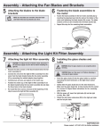
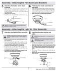
□□ Remove the three screws (RR) on the switch cup cover of the
□□
□□
light kit fitter assembly (E).
Connect the wires from the light kit fitter assembly (E) to the
wires from the switch cup of the fan-motor assembly (D) by
connecting the molded adaptor plugs together (blue to black,
white to white). Carefully tuck all wires and splices into the
switch cup.
Align the three holes in the switch cup cover of the light kit
fitter assembly (E) with the three holes in the switch cup
of the fan-motor assembly (D). Make sure the notch in the
switch cup cover of the light kit fitter assembly (E) clears the
reversing switch in the switch cup of the fan-motor assembly
(D). Position the light kit fitter assembly (E) and re-install the
three screws (RR) that were removed in first step to secure
the light kit fitter assembly (E).
□□ Insert the glass shade (H) into the light kit fitter assembly
□□
□□
(E) glass holder by carefully squeezing the steel tensioners
(TT) on the light kit fitter assembly (E) socket together.
Gently slide the glass shade (H) over the steel tensioners
(TT). Make sure the glass shade (H) is fully inserted into
the socket for a secure fit. Repeat this procedure for the
remaining glass shades (H).
With the power off, install the light bulbs (I) into the light
bulb sockets.
D
D
E
TT
H
RR
E
I
12
Ensamblaje - Cómo instalar las lámparas
1
Cómo instalar el ensamblaje del
soporte del kit de luces
2
Cómo instalar las pantallas de
vidrio y las bombillas
PRECAUCIÓN: Para disminuir el riesgo de descarga eléctrica,
desconecta el circuito de energía del ventilador antes de
instalar la lámpara.
ADVERTENCIA: Espera que la pantalla de vidrio se enfríe
completamente antes de retirarla.
NOTA: Marca la posición del interruptor deslizante del ventilador.
Este es el interruptor utilizado para cambiar la dirección de la
rotación del ventilador. Para obtener más información sobre
el funcionamiento de este interruptor, consulta Cómo usar el
ventilador y el Control remoto en la página 12.
ADVERTENCIA: Colocar bombillas de vataje incorrecto en el kit
de luces hará que las luces se apaguen hasta que se instale
las bombillas adecuadas. Apaga el kit de luces, reemplaza las
bombillas con otras de vataje correcto y vuelve a encenderlo.
NOTA: Si necesitas una caja del interruptor adicional
(o cubierta) para la opción sin luces, llama
al 1-800-283-6513 (L-V 9:00 a.m. a 4:30 p.m. hora estándar
del Este).
PRECAUCIÓN: Asegúrate de que la corriente esté cortada
antes de montar o retirar las pantallas de vidrio.
NOTA: El uso de una bombilla CFL E12 eliminará la opción de
regulación de intensidad, y puede causar parpadeos.
□□ Quita los tres tornillos (RR) en la cubierta de la caja del
interruptor del ensamblaje del soporte del kit de luces (E).
□□ Conecta los cables del ensamblaje del soporte del kit de luces
□□
□□ Inserta la pantalla de vidrio (H) en el soporte de vidrio del
(E) a los cables de la caja del interruptor del ensamblaje del
motor del ventilador (D), usando los enchufes con adaptadores
moldeados (azul con negro, blanco con blanco). Coloca con
cuidado todos los cables y empalmes dentro de la caja del
interruptor.
Alinea los tres orificios de la cubierta de la caja del interruptor
del ensamblaje del soporte del kit de luces (E) con los tres
orificios en la caja del interruptor del ensamblaje del motor del
ventilador (D). Asegúrate de que la muesca en la cubierta de
la caja del interruptor del soporte del kit de luces (E) permita
que el interruptor de reversa en la caja del interruptor del
ensamblaje del motor del ventilador (D) se mueva libremente.
Coloca el ensamblaje del soporte del kit de luces (E) y vuelve a
colocar los tres tornillos (RR) que fueron retirados en el primer
paso para asegurar el ensamblaje del soporte del kit de luces
(E).
□□
□□
ensamblaje del soporte del kit de luces (E) apretando con
cuidado los tensores de acero (TT) sobre el portabombilla
del ensamblaje del soporte del kit de luces (E).
Con cuidado desliza la pantalla de vidrio (H) sobre los
tensores de acero (TT). Asegúrate de que la pantalla de
vidrio (H) esté totalmente insertada en el portabombillas
para una colocación segura. Repite este procedimiento para
las pantallas de vidrio restantes (H).
Con la electricidad apagada, instala las bombillas (I) en los
portabombillas.
D
E
D
TT
H
I
RR
E
12