1
INSTRUCCIONES PARA LA INSTALACION
Para modelos con anillos de ajuste
AGUARDE ESTAS INSTRUCCIONES
ADVERTENCIA! CORTE LA CORRIENTE DESDE EL FUSIBLE O EL INTERRUPTOR CENTRAL.
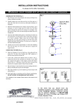
ASSEMBLING THE TRIM RING (Fig.1)
1. Desempaque cuidadosamente su nueva
lampara y coloque todas las partes en una
superfice despejada.Tenga cuidado de no
perder las partes pequeñas que son necesarias
para la instalacion.
2. Coloque el anillo de cristal (C) en el anillo
decorativo (D), luego cubra con la placa (B) y
alinee los agujeros de la placa con los agujeros
del anillo decorativo.
3. Pase los tornillos (A) por los agujeros de la
placa y apriétela al anillo decorativo.
Fig. 1
A
B
C
D
Fig. 2-A
INSTALLATION (Fig. 2)
4. Desconecte la corriente en el cortacircuitos.
5. Retire la bombilla del receso actual puede y
anillo.
6. Antes de instalar el marco de montaje reflector
a la vivienda, quite y deseche la placa de zócalo
(G) en la vivienda por la aflojando la tuerca de
mariposa (H) y el tornillo (E), como muestran en
la fig. 2-A.
7. Coloque el marco de montaje reflector en la
posición por debajo del techo, inserte los
enganches del zócalo (F) en las ranuras (K)
situado en la parte superior del marco de
montaje deflector. Pellizque las patas del resorte
(L) e inserte las patas en la "L" pestañas (I), que
sobresale de la parte interior de la vivienda y
suelte el resorte, como se muestra en la fig.
2-B. Repita con el otro resorte. Empuje el marco
hacia el techo, se ampliarán los resortes
asegurando el marco de montaje deflector en
su lugar.
8. Instalar o cambiar la bombilla (H) (no incluidas)
con el instrumento do succión (N) proporcionar
con anillo como se muestra en la fig. 2-C.
Fig. 2-B
PRECAUCIÓN: Consulte la etiqueta de la lámpara
situada cerca del portalámparas para el voltaje
máximo recomendado de la bombilla.
Fig. 2-C
(NO EXCEDA MAS
ESPECIFICADOS!).
DE
LOS
L
E TECHO
G
H
TECHO
F
I
K
L
VATIOS
TECHO
Su instalación se ha completado, vuelva a
conectar la corriente.
Nota: La illustracion en la (Fig.1&Fig.2) de este
manual es para el proposito de la instalacion
solamente. Puede variar con la lampara que
usted compro.
En caso de preguntas sobre la instalacion o le faltaron
partes, porfavor hablar al departamento de Servicio al
Cliente al 1-800-527-0998 de Lunes a Viernes de 8:00 a.m.
a 5:00 p.m. PST (Tiempo del Pacifico).
M
N
LA-1463E/S
INSTALLATION INSTRUCTIONS
For Trim Rings Models
READ AND SAVE THESE INSTRUCTIONS
W A R N I N G ! S H U T P O W E R O F F AT F U S E O R C I R C U I T B R E A K E R .
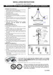
ASSEMBLING THE TRIM RING (Fig.1)
1. Carefully remove the trim ring from the carton
and check that all parts are included as shown
in the illustration.
2. Place Glass Ring (C) into Trim Ring (D), then
cover with Baffle (B) and align the holes in
Baffle with the holes in Trim Ring.
3. Thread Screws (A) through the holes in baffle
and tighten it to Trim Ring.
INSTALLATION (Fig. 2)
4. Shut off power at the circuit breaker.
5. Remove the bulb from the recess can and
current trim ring.
6. Before installing frame baffle assembly to
housing, remove and discard the socket plate
(G) in housing by loosening Wing Nut (H) and
Studs (E) as show in Fig. 2-A.
7. Place the frame baffle assembly in position
under the ceiling, insert the clips of Socket (F)
into the Slots (K) located on the top of frame
baffle assembly. Pinch the legs of the Butterfly
Spring (L) and insert the legs into the “L” tabs
(I) protruding from the inside of the housing
and release the butterfly spring as shown in
Fig. 2-B. Repeat with other spring. Push the
frame baffle trim up towards the ceiling, the
springs will expand and lock the trim in place.
8. Install or replace the Light Bulb (M) (not
included) with Suction Cup Tool (N) provide
with trim ring as shown in Fig. 2-C.
Fig. 1
A
B
C
D
Fig. 2-A
E CEILING
G
H
Fig. 2-B
CEILING
CAUTION: Refer to the relamping label located
near the lamp holder for recommended maximum
bulb wattage.
(DO
NOT
EXCEED
RECOMMENDED
MAXIMUM WATTAGE !!).
Your installation is now complete turn power back
on.
L
F
I
L
K
Fig. 2-C
Note: Illustration (Fig.1& Fig.2) on this manual
is for installation purposes only. It may or may
not be identical to the fixture purchased.
CEILING
M
N
In the event that you should have any installation question or are
missing parts, please contact Customer Service. Customer
service may be reached weekdays a 1-800-527-0998 between the
hours of 8:00am and 5:00pm PST (Pacific Standard Time).
LA-1463E/S