1
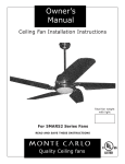
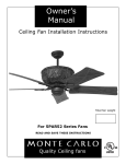
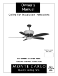
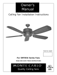
Owner’s Guide and Installation Manual
8ATR44XXD-L Series Fan
UL Model No. : AC-40448
Attach sales receipt to this card and retain as your proof of purchase
DATE OF PURCHASE:
RETAILER NAME:
MODEL NUMBER:
RETAILER ADDRESS:
To register your fixture, please visit our website www.montecarlofans.com
14.3kgs
31.5 lbs
Total fan weight with light kit
WARNING: TO REDUCE THE RISK OF FIRE, ELECTRIC SHOCK, OR INJURY TO PERSONS, OBSERVE THE FOLLOWING
READ AND SAVE THESE INSTRUCTIONS
Installation work and electrical wiring must be done by qualified person(s) in accordance with applicable codes and standards (ANSI/NFPA
70-1999), including fire-rated construction.
Use this unit only in the manner intended by the manufacturer. If you have any questions contact the manufacturer.
After making the wire connections, the wires should be spread apart with the grounded conductor and the equipment-grounding conductor
on one side of the outlet box and ungrounded conductor on the other side of the outlet box. The splices, after being made, should be
turned upward and pushed carefully up into the outlet box.
WARNING: Before you begin installing the fan, servicing or cleaning unit, Switch power off at Service panel and lock service disconnecting
means to prevent power from being switched on accidentally. When the service disconnecting means cannot be locked, securely fasten a
prominent warning device, such as a tag, to the service panel.
Be cautious! Read all instructions and safety information before installing your new fan. Review the accompanying assembly diagrams.
When cutting or drilling into wall or ceiling, do not damage electrical wiring and other hidden utilities.
Make sure the installation site you choose allows the fan blades to rotate without any obstructions. Allow a minimum clearance of 7 feet
from the floor to the trailing edge of the blade.
WARNING: To Reduce The Risk Of Fire, Electric Shock, or Personal Injury, Mount To Outlet Box Marked “Acceptable for Fan Support of
15.9 kg (35 lbs) or less” And Use Mounting Screws Provided With The Outlet Box.
CAUTION: For Compliance with Local Codes and Regulations, If Installing The Secondary Support Safety Cable in the U.S., Do Not Remove Knockouts In The Outlet Box. Mount the secondary support safety cable through the reserved nail/screw hole on the outlet box to
the building structure (or the ceiling joist).
WARNING: To reduce the risk of personal injury, do not bend blade holders during installation to motor, balancing or during cleaning. Do
not insert foreign object between rotating blades.
Attach the mounting bracket using only the hardware supplied with the outlet box.
WARNING: To reduce the risk of fire or electric shock, this fan must be installed with an isolating wall control/switch.
WARNING: To reduce the risk of fire or electric shock, this fan should only be used with fan speed control part no. UC7067RC manufactured by Rhine Electronic Co., Ltd.
WARNING: To reduce the risk of fire or electric shock, do not use this fan with any solid state fan speed control device, or variable speed
control.
If this unit is to be installed over a tub or shower, it must be marked as appropriate for the application.
Never place a switch where it can be reached from a tub or shower.
The combustion airflow needed for safe operation of fuel-burning equipment may be affected by this unit’s operation. Follow the heating
equipment manufacturer’s guideline safety standards such as those published by the National Fire Protection Association (NFPA), and the
American Society for Heating, Refrigeration and Air Conditioning Engineers (ASHRAE) and the local code authorities.
CAUTION: To Reduce the Risk of Electric Shock, Disconnect the electrical supply circuit to the fan before installing the light kit.
All set screws must be checked and tightened where necessary before installation.
Tools Required for Assembly (not included): Electrical Tape, Phillips Screwdriver, Pliers, Safety Glasses,
Stepladder and Wire Strippers.
Customer Service
800-969-3347
Customer Service Center
7400 Linder Ave.
Skokie, IL 60077
www.montecarlofans.com
© 2011 Monte Carlo Fan Company
2
3/2/2012
3
1
2
Before you begin installing the fan, Switch power off
at Service panel and lock service disconnecting
means to prevent power from being switched on accidentally. When the service disconnecting means
cannot be locked, securely fasten a prominent warning device, such as a tag, to the service panel.
Before installing this fan make sure the outlet
box is properly installed to the house structure.
To reduce the risk of fire, electric shock, or personal injury, mount to outlet box or supporting
system acceptable for fan support.
(Mounting must support at least 35 lbs.)
4
5
6
Loosen screw holding half ball and
remove pin from downrod. Thread
wires and safety cable through downrod and insert downrod into motor
yoke.
Insert clevis pin through yoke and
downrod and secure with keeper pin.
(see inset)
7
8
9
Tighten both yoke set screws and
lock nuts to further secure downrod.
Install upper glass over downrod
onto fan body.
Install canopy over downrod. Caution: Replace pin and ball onto downrod.
Install 4 x 15 watt candelabra torpedo shape bulbs.
© 2011 Monte Carlo Fan Company
3
Install the Mountiing Bracket to the
Outlet box. Use only the screws
provided with the outlet box.
3/2/2012
10
12
11
Safety cable installation
Safety Cable
Lag Screw
safety
cable
washer
3” lag
screw
Tighen set screw loosened in step 5.
13
Carefully lift fan assembly onto mounting
bracket. Rotate fan so that the notch on the ball
engages the ridge in the mounting bracket. This
will allow hands-free wiring.
lock
washer
For Canadian installation and for USA fan and light
kit combinations over 35 lbs, in both flush and
downrod modes the safety cable must be installed
into the house structure beams using 3” lag
screws, washers and lock washers provided. Make
sure that when the safety cable is fully extended
the lead wires are longer than the cable and no
stress is placed on the lead wires.
Note:If Installing The Secondary Support Safety
Cable in the U.S., Do Not Remove Knockouts In
The Outlet Box.
15
14
fuses
Fan
House
white
white
black
Remote Transmitter Dip swtiches
orange
blue
Remote Receiver Dip switches
Set dip switches on the Remote Transmitter and
Remote Receiver to the same settings. This must
be done so the units will communcate properly. If
you have other fans you can set to control from
one transmitter by setting both receivers the same
as the transmitter. If you have more than one fan
with remote. You can set the dip switches to different positiosns to have seperate control.
16
Make wire connections to power source using
wire nuts provided. Make sure that no filiments
are outside of the wirenut. After making the
wire connections, the wires should be spread
apart with the grounded conductor and the
equipment-grounding conductor on one side of
the outlet box and ungrounded conductor on the
other side of the outlet box.
© 2011 Monte Carlo Fan Company
Install remote receiver by sliding into opening in
the mounting bracket. Make sure that the dip
switches on the transmitter and the receiver are
set to the same positions.
17
black
Green
Make wiring connections as indicated above.
White from fan to white from remote marked
N. Orange from fan to Orange from remote
marked Light/up. Blue from fan to blue from
remote marked down light. Black from fan to
Black from remote marked L. White from
house to white from remote marked AC N .
Black from house to Black from remote
marked AC L. Connect all green ground wires
to Ground wire from House.
18
Raise the canopy up and align the
two holes in the canopy with the two
holes in the hanger bracket. Secure
with two screws provided.
4
Install 1 x 100 watt JD E-11 halogen bulb. Do
not touch bulb surface as oily residue from skin
can cause the bulb to explode. Bulb included.
WARNING: Over lamping the fan will result in the fan lights shutting down
until the proper wattage of bulbs are
installed. Reset the lights by turning off
the wall switch, breaker,or by remote. Replace bulbs with the correct wattage bulbs,
turn the power on.
3/2/2012
19
20
21
Install glass to fan.
Install glass to fan using the 3 ball
screws provided.
Attach blade assembly to arms from
motor housing using screws and
washers provided. Tighten screws securely.
22
23
24
Remove cover by snaping off from top or bottom. Remove battery cover. Install 12V battery
into wall remote. Duracell MN21 / Eveready
A23 / GP 23A all 12V.Attach cover of remote by
placing over buttons and snap the battery cover
in place.
HAND HELD INSTALL
Place face plate over battery compartment and
buttons. Place remote over 2 pins on front cover.
Attach cover of remote by placing over 4 pins and
snaping into place.
WALL MOUNT INSTALL
Install wall control unit to outlet box
using machine screws provided.
25
Attach front cover to wall control
with screws provided. Snap battery
cover in place.
© 2011 Monte Carlo Fan Company
5
3/2/2012
Remote Control Transmitter Features:
LED LIGHT
FAN REVERSE
(Press once to
change direction of
the fan)Fanmust be
running to reverse.
MEDIUM SPEED
HIGH SPEED
LOW SPEED
FAN OFF SETTING
(Turns fan off only)
UPLIGHT ON/OFF SETTING AND DIMMER
(Press and hold to dim
light infinitively)
DOWNLIGHT ON/OFF
SETTING AND DIMMER
(Press and hold to dim
light infinitely)
FAN SPEED Depress “1 dot” for low speed, “2 dots” for medium or “3 dots” for
high. To turn fan off press square”.
LIGHT DIMMER To turn light on, press light dimmer once quickly. To turn off
press once quickly while light is on. To dim light hold down button “light dimmer”.
The light will cycle from bright to dim to bright until button is released. Light will
maintain last setting if turned off.
FORWARD/REVERSE Depress rev button allow a few seconds for remote to
change rotation direction with fan running.
© 2011 Monte Carlo Fan Company
6
3/2/2012
Trouble Shooting
If you have difficulty operating your new ceiling fan, it may be the result of incorrect assembly, installation, or wiring. In
some cases, these installation errors may be mistaken for defects. If you experience any faults, please check this Trouble Shooting Chart. If a problem cannot be remedied, or you are experiencing difficulty in installation, please call our
Customer Service Center at the number printed on your parts list insert sheet.
Warning: Before servicing or cleaning unit, Switch power off at Service panel and lock service disconnecting
means to prevent power from being switched on accidentally. When the service disconnecting means cannot be locked, securely fasten a prominent warning device, such as a tag, to the service panel.
Suggested Remedy
Trouble
1. If fan does not start:
1.Check main and branch circuit fuses or circuit breakers.
2.Check line wire connections to fan and switch wire connections in switch housing.
3.Check to make sure the dip switches from the transmitter and receiver are set on the same
frequency.
CAUTION: Make sure main power is turned off
2. If fan sounds noisy:
1.Check to make sure
2.Check to make sure
3.Check to make sure
or against the interior
all screws in motor housing are snug (not over tightened).
the screws which attach the fan blade holder to the motor are tight.
wire nut connectors in switch housing are not rattling against each other
wall of the switch housing.
CAUTION: Make sure main power is turned off before entering switch housing.
4.Some fan motors are sensitive to signals from Solid State variable speed controls. DO NOT
USE a Solid State variable speed control.
5.Allow "break-in" period of 24 hours. Most noises associated with a new fan will disappear
after this period.
3. If fan wobbles:
1.Make sure that the ridge of the canopy engages the notch in the downrod ball.
2.Check that all blades are screwed firmly into blade holders.
3.Check that all blade holders are tightened securely to motor.
4.Make sure that canopy and mounting bracket are tightened securely to ceiling junction box
and junction box is mounted firmly to ceiling joist.
5.Dynamic balancing involves ‘counter-weighting’. By using a small weight opposite to the
point of wobble, you can in almost all cases eliminate the wobble. The procedure requires
much trial and error, and a certain amount of patience to achieve the correct position of the
counterweight. A) Determine which fan speed causes the most wobble. This will almost always
be the highest speed. B) Turn the fan off. Select any one blade and place the balance clip half
way between the blade tip and blade holder, on the rear edge of the blade. Caution: Be careful to stay clear of the blades when running. If the clip is not secure, injury may result from the clip flying off. C) Turn the fan on. Observe if the wobble is better or worse.
Turn the fan off and move the clip to the next blade. Do the same for all blades and note on
which blade the clip improves the wobble the most. D) Place the clip on the blade which
showed the most improvement and by trial and error move the clip in and out along the blade
to find the position which most improves the wobble. E) Remove the clip and discard. Once the
exact position is determined, place a weight on bottom of the metal blade holder on its centerline. Press the weight firmly to ensure it is firmly attached to the blade holder. Add more
weight as needed to balance.
4. If light does not work:
1.Check wire from fan to make sure it is connected to hot wire from house.
2.Check for loose or disconnected wires in fan switch housing.
3.Check for loose or disconnected wires in light kit.
4.Check for faulty light bulbs.
WARNING: Over lamping the fan will result in the fan lights shutting down
until the proper wattage of bulbs are installed.
Reset the lights by turning off the wall switch, breaker,or by remote. Replace bulbs
with the correct wattage bulbs, turn the power on.
CAUTION: Make sure main power is turned off before entering switch housing.
WARNING: Before attempting to replace the fuse make sure the main power is turned
off to the fan. Replace only with a 3 amp fuse. (Fuse is inside the canopy on the blue
and orange wires to remote receive, push and twist the cap to open the fuse case).
© 2011 Monte Carlo Fan Company
7
3/2/2012
Mar.2012 New format
May.2013 Update for CUL regulation