1
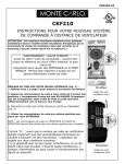
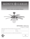
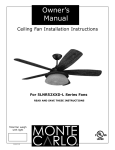
16002-15
16002-15
INSTRUCTIONS FOR YOUR NEW
REMOTE FAN CONTROL SYSTEM
CAUTION:
This remote only works with some fans in sloped ceiling model.
Do not use fan speed control in canopies where the mountng is
not as described in figure 6,7.
WARNING - HIGH VOLTAGE
Before Connecting the Control Unit:
•Remove electrical power from circuit to be used.
•Household power can cause SERIOUS INJURY or
DEATH.
•Wiring must meet all local electrical code requirements.
A. SETTING THE CODE ON YOUR NEW REMOTE (Fig. 1):
1. Remove battery cover
* Refer to pg 5 for removing battery cover.
2. Slide code switches to your choice of UP and DOWN positions.
Factory setting is all UP. Do not use this setting.
•Use ball point pen or small screwdriver.
•Slide firmly up or down.
Transmitter
Code switches
Fig.1
B. SETTING THE CODE ON YOUR NEW CONTROL UNIT (Fig. 2)
1. Slide code switches to the same positions as set on
your REMOTE.
NOTE: The code switches on the TRANSMITTER and the RECEIVER
UNIT must be set to the same positions to work.
The item “IC:” before the radio certification number only signifies that
Industry Canada Technical specifications were met.
Operation is subject to the following two conditions: (1) this device may
not cause interference, and (2)this device must accept any interference,
including interference that may cause undesired operation of the device.
Receiver
Code switches
Fig.2
16002-15
LIMITED WARRANTY
A. GEOGRAPHIC SCOPE - This warranty applies to products purchased in the United States and Canada.
B. What is Covered? Any defect in material or workmanship.
C. For how long from date of purchase? All finished products - one year; all spare parts - 90 days.
D. Who gets the warranty? This warranty is limited to the customer who originally purchased the product..
E. LIMITATIONS: IMPLIED WARRANTIES, INCLUDING THOSE OF FITNESS FOR A PARTICULAR PURPOSE
AND MERCHANTABILITY (AN UNWRITTEN WARRANTY THAT THE PRODUCT IS FIT FOR ORDINARY USE), ARE
LIMITED TO ONE YEAR FROM THE DATE OF PURCHASE.
WILL NOT PAY FOR: LOSS OF TIME; INCONVENIENCE; LOSS OF USE OF YOUR PRODUCT OR PROPERTY DAMAGE CAUSED BY YOUR PRODUCT OR ITS
FAILURE TO WORK; ANY SPECIAL, INCIDENTAL OR CONSEQUENTIAL DAMAGES; OR ANY DAMAGES
RESULTING FROM MISUSE OR MODIFICATION OF YOUR PRODUCT.
SOME STATES DO NOT ALLOW LIMITATIONS ON HOW LONG AN IMPLIED WARRANTY LASTS OR THE
EXCLUSIONS OF INCIDENTAL OR CONSEQUENTIAL DAMAGES, SO THE ABOVE EXCLUSIONS MAY NOT APPLY
TO YOU.
F. How to obtain warranty service: To obtain warranty service for your product, you must provide proof
of the date and place of purchase of the product.
1. Do-it-yourself service - Call the Consumer Line at 800-519-4092. Trained representatives will
assist you in diagnosing the problem and will arrange to supply you with the required part for do-it-yourself
repairs.
G. What this warranty does not cover: This warranty does not cover service charges, batteries, installation, defects resulting from accidents, or damage resulting from alterations, misuse or abuse, lack of proper
installation or maintenance, failure to follow instructions, unauthorized repair, damage caused by affixing of
any attachment not provided with the product, failure of supporting devices not supplied as original mounting hardware, exposure to extremes of heat or humidity, incorrect wiring, or voltages, or failures caused by
modifications of the product, fire, flood, or acts of God.
THIS WARRANTY IS THE ONLY ONE WE WILL GIVE ON YOUR PRODUCT. IT SETS FORTH ALL OUR RESPONSIBILITIES REGARDING YOUR PRODUCT. THERE ARE NO OTHER EXPRESS OR IMPLIED WARRANTIES.
TROUBLESHOOTING GUIDE
FAILS TO OPERATE
-Is there power to the Control Unit?
-Is the Control Unit wired correctly?
-Are the fan and light switches set on the highest
position?
-Is there a good battery in the REMOTE? If the red
indicator lights when either button is pushed, the
battery still may be bad.Try changing your battery
first.
-Are the switches set the same in both REMOTE and
the Control Unit?
SHORT RANGE
NOTICE
Your Ceiling Fan and Light Assembly Must Meet the
Following Requirements:
DO NOT USE WITH SOLID-STATE FANS.
ELECTRICAL:
120 Volts AC 60 Hz.
Max Motor Amps 1.0 - CEILING FAN ONLY
Max Light Watts - 240 INCANDESCENT ONLY
MECHANICAL:
The decorative housing (CANOPY) at the ceiling Must
Be Metal.
The metal housing acts as a protective cover for the
Control Unit.
If the REMOTE operated the Control Unit when close
to it but does not operate it at distances of 30 to 40 DO NOT USE WITH A NON-METALLIC HOUSING
feet, try placing the Black Antenna wire above the
ceiling and outside of the junction box.
ONE YEAR LIMITED WARRANTY
FOR HELP
Call Customer Help Line at: 800-519-4092
CUSTOMER HELP LINE AVAILABLE for INSTALLATION AND TROUBLESHOOTING
16002-15
INSTRUCTIONS
FOLLOW ALL SAFETY INSTRUCTIONS IN YOUR CEILING FAN INSTRUCTION MANUAL.
*REMEMBER TO REMOVE ELECTRICAL POWER BEFORE STARTING WORK.*
WIRING MUST MEET ALL ELECTRICAL CODES.
A. MAKING THE ELECTRICAL CONNECTIONS (See Fig. 3)
USE WIRE NUTS FOR ALL CONNECTIONS
RED
1.
2.
3.
4.
5.
6.
7.
8.
9.
10.
11.
Remove electrical power from the circuit.
FOR FANS ON A DOWNROD: Remove ceiling fan CANOPY from its mounting plate. Go to
step 4.
FOR FLUSHMOUNT FANS: Remove decorative housing from mounting plate. (See Fig. 4)
FOR FLUSHMOUNT FANS: Disconnect mounting bracket from mounting plate and
allow to hang from one side. (See Fig. 5)
Disconnect existing wiring from supply at ceiling.
Connect GREEN fan wire to BARE (ground) wire.
Connect BLACK Control Unit wire to BLACK supply wire (AC L).
Connect WHITE Control Unit wire to WHITE wire of supply (AC N)
Connect WHITE Control Unit wire (MOTOR N) to WHITE fan wire.
Push the connected wires up into the junction box. Place BLACK wires on one side of box,
and WHITE, GREEN and BARE wires on the other side of the box.
Connect RED Control Unit wire (MOTOR L) to BLACK fan wire.
Connect BLUE Control Unit wire (FOR LIGHT) to BLUE light wire.
16002-15
12. Push the connected wires up into the junction box.
13. Lay the BLACK Control Unit wire (Antenna) on top of the Control Unit.
14. FOR FANS ON A DOWNROD: Lay the Control Unit in the CANOPY. (See Fig 6)
FOR FLUSHMOUNT FANS: Attach Control Unit to mounting plate or to ceiling with tie wraps supplied. (See
Fig 7)
NOTE: If the unit does not fit properly between the mounting plate and ceiling, attach the unit to the
underside of the mounting plate.
15. FOR FANS ON A DOWNROD: Reinstall the CANOPY on its mounting plate, Go to step 17.
FOR FLUSHMOUNT FANS: Reconnect mounting bracket to mounting place. (See Fig. 4)
16. FOR FLUSHMOUNT FANS: Reinstall the decorative housing on its mounting plate.
17. Restore electrical power to the circuit.
IMPORTANT!
Fan Installation must be complete INCLUDING ASSEMBLY OF
BLADES
before testing remote control unit.
1. This unit operates on one 12 volt battery (included).Duracell MN21/Eveready A23/GP23A all 12v.
2. Store the controller unit away from excess heat or humidity.
3. This remote control unit is equipped with 16 code combinations. Because of the many combinations, interference
from other remotes is possible (i.e. garage openers, car alarms, security systems, etc.). If your fan/light goes
on or off
without using your remote, simply change the codes on both the control unit in the fan and in your remote
transmitter.
4. THE FAN AND LIGHT MUST BE SET AT THEIR HIGHEST/BRIGHTEST SETTINGS BEFORE STARTING! In order
to operate your fan using the remote, make sure the fan is set on “HIGH” and the light is in the “ON” or
“BRIGHTEST”
position by using the pull chain controls originally supplied with your fan.
5. Operation buttons on the panel of the transmitter:
••• - For FAN High speed
•• - For FAN Medium speed
• - For FAN Low speed
Square - For FAN Off
- For Light brightness and on/off control
6. To turn ON the FAN - press the selected speed button to run the fan at the desired speed.
7. To turn OFF the FAN-press the “Square” button
8. For LIGHT control • Turn the light on or off by pressing the light button.
• If you keep the light button pressed, the light will dim, go off and
come back on at the brightest level. The light will continue
to make this cycle until the button is released.
*If you turn your power source off, the settings on your fan and light will remain the same when you turn the
power back on.
YOUR REMOTE NOW HAS FULL CONTROL OF THE FAN LIGHT
16002-15
The wall control transmits the command signals via radio waves to the receiver
installed in the fan’s hanging bracket or on the fan. The receiver is required for
the wall control to function. Power for the wall control comes from the 12V battery located in the wall remote. Duracell MN21 / Eveready A23 / GP 23A all 12V.
The frequency switches (dip switches) on the wall control and the receiver have
been preset at the factory. Please recheck to make sure the switches on the wall
control and receiver are set to the same position. Any combination of settings are
fine as long as the wall control and ceiling fan receiver are set to the same position.
CAUTION: TURN OFF POWER AT FUSE BOX TO AVOID POSSIBLE ELECTRICAL SHOCK.
HAND HELD INSTALL
1
2
Remove cover by snaping off from top or bottom. Remove battery cover. Install 12V battery
into wall remote. Duracell MN21 / Eveready A23
/ GP 23A all 12V.
Place face plate over battery compartment and
buttons. Place remote over 2 pins on front
cover. Attach cover of remote by placing over 4
pins and snaping into place.
3
WALL MOUNT INSTALL
Install wall control unit to outlet box
using machine screws provided.
4
Attach front cover to wall control
with screws provided. Snap battery
cover in place.
16002-15
Remote Control Transmitter Features:
LED LIGHT
MEDIUM SPEED
LOW SPEED
FAN OFF SETTING
(Turns fan off only)
HIGH SPEED
LIGHT ON/OFF SETTING AND DIMMER
(Press and hold to
dim light infinitively)
FAN SPEED Depress “l dot” for low speed, “2 dots” for medium or “3 dots” for
high. To turn fan off press square”.
LIGHT DIMMER To turn light on, press light dimmer once quickly. To turn off
press once quickly while light is on. To dim light hold down button “light dimmer”.
The light will cycle from bright to dim to bright until button is released. Light will
maintain last setting if turned off.
For Customer Service Call
866-449-2821