1
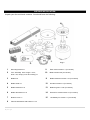
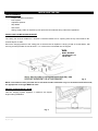
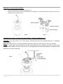
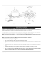
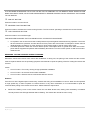
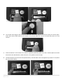
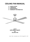
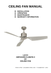
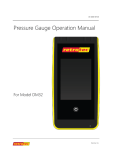
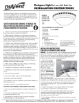
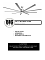
DC CEILING FAN MODELS ICF72, ICF96 - INSTALLATION OPERATION MAINTENANCE WARRANTY INFORMATION CAUTION CAUTION READ INSTRUCTIONS CAREFULLY FOR SAFE READ INSTRUCTIONS CAREFULLY FOR SAFE INSTALLATION ANDAND FANOPERATION. OPERATION. INSTALLATION CONGRATULATIONS ON YOUR PURCHASE Congratulations on purchasing the latest in energy saving ceiling fans. This fan runs on DC (direct current) power which gives it the benefit of being super energy efficient whilst still maintaining high volume air-movement and silent operation. Energy Saving – The DC motor is the latest technology in fan design. Its highly efficient motor saves up to 65 % more energy than ceiling fans with traditional AC motors. Silent Operation – This DC fan motor is programmed with a stabilized current which efficiently reduces motor noise. Low Operating Temperature – The DC power is managed effectively which brings down the motor operating temperature to less than 50degs. This results in a much cooler motor than a standard AC fan and increases the longevity of the motor. 6 Speed Remote Control – While regular AC ceiling fans usually come with only 3 speeds, this DC fan comes complete with a 6 speed remote, which gives greater choice of comfort levels. SAFETY PRECAUTIONS 1) This appliance is NOT intended for use by persons (including children) with reduced physical, sensory or mental capabilities, or lack of experience and knowledge, unless they have been given supervision or instruction concerning use of the appliance by a person responsible for their safety. 2) Children should be supervised to ensure that they do not play with the appliance. 3) An all-pole disconnection switch must be incorporated in the fixed wiring in accordance with the wiring rules. 4) Do not dispose of electrical appliances as unsorted municipal waste, use separate collection facilities. Contact your local government for information regarding the collection systems available. If electrical appliances are disposed of in landfills or dumps, hazardous substances can leak into the groundwater and get into the food chain, damaging your health and well-being. 5) The structure to which the fan is to be mounted must be capable of supporting a weight of 40kg. 6) The fan should be mounted so that the blades are at least 7 ½ feet above the floor. 7) This fan is suitable for indoor and outdoor areas provided the fan is fully undercover with a minimum of 2 walls. The ceiling fan must be positioned in a location protected from water, wind, dust and salt. Exposure to these elements will void the warranty. Mounting the fan in a situation where it is subject to water or moisture is dangerous. 8) Only an authorized electrician should execute the installation. 1|Page BEFORE INSTALLATION Unpack your fan and check contents. You should have the following: Fig. 1 1 Mounting bracket x 1 9 Extra motor screws x 1 (not shown) 2 Fan assembly with hanger cover, down rod, canopy cover and canopy x 1 10 Blade screws x 28 (not shown) 3 Blades x 9 11 Blade bracket kit screws x 10 (not shown) 4 Blade holder x 1 12 Wooden screws x 2 (not shown) 5 Blade bracket kit x 9 13 Balancing kits x 1 set (not shown) 6 Blade decorative kit x 9 14 Screws for remote holder x 2 (not shown) 7 Bottom cover x 1 15 12V Battery for remote x 1 (not shown) 8 Remote transmitter with holder x 1 set 2|Page INSTALLING THE FAN TOOLS REQUIRED: - Phillips / flat head screwdriver - Pair of pliers - Adjustable spanner - Step ladder - Wire cutter - Wiring, supply cable as required by local provincial and national wiring codes and regulations. INSTALLING THE MOUNTING BRACKET The ceiling fan must be installed in a location so that the blades are 1 ft. spacing from the tip of the blade to the nearest objects or walls. Secure the hanging bracket to the ceiling joist or structure that is capable of carrying a load of at least 90lbs., with two long screws provided. Ensure at least 1 ½ in. of the screw is threaded into the support. BEAM MUST BE ABLE TO SUPPORT UP TO 90 LBS. Fig. 2 NOTE: The bracket screws provided are for use with wooden structures only. For structures other than wood, the appropriate screw type MUST be used. ANGLED CEILING INSTALLATION This fan hanging system supports a maximum 20 degree angled ceiling installation. Fig. 3 3|Page HANGING THE FAN MOTOR ASSEMBLY Lift the fan assembly onto mounting bracket. Fig. 4 Ensure the notch of the ball joint is positioned on the stopper of the mounting bracket to prevent the fan from rotating when in operation. Fig. 5 Mounting Bracket Stopper of bracket Notch of ball joint Fig. 4 Fig. 5 PREPARE AND COMPLETE THE ELECTRICAL WIRING — WIRING DIAGRAM (FIG. 6) WARNING: FOR YOUR SAFETY ALL ELECTRICAL CONNECTIONS MUST BE UNDERTAKEN BY A LICENSED ELECTRICIAN. NOTE: AN ADDITIONAL ALL POLE DISCONNECTION SWITCH MUST BE INCLUDED IN THE FIXED WIRING. NOTE: IF THERE ARE TWO OR MORE DC CEILING FANS INSTALLED IN THE ONE LOCATION, AN ISOLATION SWITCH IS REQUIRED FOR EACH CEILING FAN. THIS IS REQUIRED W HEN PROGRAMMING THE REMOTE AND RECEIVER TO PAIR TOGETHER. Fig. 6 4|Page INSTALL CANOPY COVER Loosen 2 screws from the bottom of the mounting bracket. Slide the canopy up to the mounting bracket and place the key hole on the canopy over the screw on the mounting bracket, turn canopy until it locks in place at the narrow section of the key holes, secure it by tightening the two set screws. Avoid damaging the electrical wiring prepared previously. Finally attach the canopy cover to canopy and secure it by pushing the lugs into the holes. Fig. 7 BLADE INSTALLATION Attach the blade holder to the motor by lining up the position label (1, Fig. 8) and secure it by tightening 6 screws (Fig 9.) Insert the blade screws through the blade assembly in the following order—blade holder, blade and blade bracket kit. Then secure the blade to the blade holder by tightening the 3 screws (Fig. 10). Push the blade decorative kit into the end of the blade and secure it by tightening the screw. Repeat to install the other blades to the blade holder. Finally install the bottom cover to the shaft of the motor by rotating it clockwise (Fig.11). Fig. 8 5|Page Fig. 9 Fig. 11 Fig. 10 USING YOUR CEILING FAN Pairing Transmitter and Receiver – when 2 or more DC ceiling fans are installed in one location When two or more fans are located near each other, you may want to have the receiver/transmitter for each fan set to a different code, so that the operation of one fan does not affect the operation of the other fans. The DIP switches for the transmitter (remote hand piece) are located in the battery compartment of the transmitter. Configuring the DIP switches will allow a unique transmission code assigned to each fan ceiling. NOTE: Ensure that you have installed an all - pole disconnection switch in the fixed wiring for each fan, when using DIP code function. NOTE: Ensure power to the Receiver is ON prior to pairing the transmitter with the receiver. Transmitter/Receiver pairing for ceiling fan 1: Turn off both ceiling fans 1 and 2 via the mains supply to the receiver. Slide the cover of the battery compartment of the transmitter to access the DIP switches. This will be transmitter 1. Change the position of the DIP switches in the remote transmitter 1, so that it will be different to transmitter 2. Fig. 8 Install the 12VDC battery in the compartment. Please make sure the polarity of the battery is correct. Turn on the power to receiver 1. Keep the power OFF to receiver 2. (Each ceiling fan must have its own isolation switch, so that only the ceiling fan that needs to be paired with the transmitter will be ON). 6|Page Press and hold the SET button of transmitter 1 for 6 seconds within 60 seconds of switching the power to the receiver of ceiling fan 1. Now the transmitter should be paired with the receiver of ceiling fan 1. Turn ON/OFF or change the speed of ceiling fan 1 by the transmitter to check the operation. Setting DC Ceiling fan 2: Turn off both ceiling fans 1 and 2 via the mains supply to the receiver. Slide the cover of the battery compartment of the transmitter to access the DIP switches. This will be transmitter 2. Change the position of the DIP switches in the remote transmitter 2, so that it will be different to transmitter 1. Fig. 8 Install the 12VDC battery in the compartment. Please make sure the polarity of the battery is correct. Turn on the power to receiver 2. Keep the power OFF to receiver 1. (Each ceiling fan must have its own isolation switch, so that only the ceiling fan that needs to be paired with the transmitter will be ON). Press and hold the SET button of transmitter 2 for 6 seconds within 60 seconds of switching the power to the receiver of ceiling fan 2. Now the transmitter should be paired with the receiver of ceiling fan 2. Turn ON/OFF or change the speed of the ceiling fan 2 by the transmitter to check operation. Note: The pairing of Transmitter and Receiver is not required if only one ceiling fan is installed. When more than two ceiling fans are installed near each other, please refer to the instruction above. Fig. 8 Remote Control Buttons 1 - FAN SPEED CONTROL BUTTON: ○ There are 6 available speeds. I button is for the lowest speed, and ○ VI button is for the fastest speed. ○ NOTE: WHEN YOU TURN ON THE FAN FOR THE FIRST TIME OR SWITCH THE MAIN POWER TO THE CONTROLLER, YOU NEED TO START THE FAN ON HIGH “○ VI ” SPEED FIRST AND THEN CHOOSE A LOW ER SPEED. 7|Page Fig. 9 tes t 5-10 SECONDS IS REQUIRED TO ALLOW THE DC FAN TO RESPOND TO THE REMOTE EACH SPEED OR FAN DIRECTION SELECTIONS, AS DC FANS INCORPORATE A SENSOR CONTROL W HICH CONTROLS THE POWER TO THE MOTOR. 2 - FAN OFF BUTTON: ○ Press the button to turn the fan off. 3 - REVERSE FUNCTION BUTTON: ○ Press the button to activate the reverse running function. The fan must be operating to activate the reverse function. 4 - LIGHT CONTROL BUTTON: ○ Press the button to turn on/off the light. THE RECEIVER PROVIDES THE FOLLOWING LEVEL OF PROTECTION AGAINST. Lock position: the receiver has a built in safety feature to protect against obstruction during operation. The motor will be locked from operation and will disconnect from power after 30 seconds of interruption. Please remove obstacles before re-starting. To reset, simply turn off the power supply to the fan motor and re-start. Over 80W protection: When the receiver detects power consumption which is greater than 80W, the receiver power will be stopped and operation will immediately discontinue. Turn the receiver power on after 5 seconds to restart the fan. REPAIRING THE FAN RECEIVER & REMOTE PAIRING Should the remote and receiver lose control after installation or during use, the pairing of the remote and the receiver must be repaired. Below are the operating symptoms and method to repair the pairing of the DC ceiling fan remote and receiver. Issues: Loss of control - Fan is only running at high speed after installation Loss of control - No reverse function after installation Loss of control - Remote cannot communicate with the receiver Solution: If the fan runs at the highest speed continuously, it means the wiring of the installation is correct. When the fan operates on high speed only, or fails to operate in reverse function or any other command/s, it is recommended to repair the communication pairing of the remote and receiver. Please follow the steps below: A. Remove the battery cover on the remote. Check the 434 MHz sticker area, making sure the battery is installed correctly and the red LED light indicator will be flashing. This means the remote function is okay. 8|Page tes t B. Turn off the main supply to the receiver for more than 30 seconds and turn on the main supply to receiver again. Press and hold the SET button on the remote for 6 seconds within 60 seconds of turning the power on to the receiver. C. Press the buttons on the remote to run the fan. In general, performing point A, B, and C should repair the remote and receiver and will allow full control of the fan. If not, please do the next step. D. The DIP switches on the fans are set up at the factory. The DIP switch can be changed to any location in 16 options. (Eg. up-up-down-down). 9|Page tes t E. Please repeat the (A)-(C) steps to check the function. If the issues still persist after following point (A) to (D) and there is still no control, then please contact the local retailer for a new remote or transmitter. NOTE: For your safety, a new receiver must be installed by a licensed electrician. NOTE: While repairing the DC ceiling fan remote and receiver is in process, the fan operates at highest speed with REVERSE mode automatically for 90 seconds, and then operates with FORWARD mode for 90 seconds. During the paring process, do not press any key on the remote. BALANCING / WOBBLING TROUBLESHOOTING Please note that not all ceiling fans are the same, even in the same model—some may move more or less than others. Movement of a couple of centimetres is quite acceptable and does not suggest that the fan will fall down. Even though all blades are weighted and grouped by weight, it is impossible to eliminate wobble altogether. This s hould not be considered a fault. Ceiling fans tend to move during operation due to the fact that they are not generally rigidly mounted. You may do the following action to reduce the wobbling: 1) Check all the blade mounting screws are tightened and securely. 2) Wobbling problems may result from inconsistent blade level. To check blade level, measure the distance from each blade tip to the ceiling. Note: If measurements are inconsistent: - Check that the blade mount screws are not over tightened or loose, which can cause the blade tip to not sit level; - An out of shape blade can cause wobbling, check by removing the blade and lay it on a flat surface. A good flat blade will lay flat on the surface. 3) Blade tracking may be checked simply by use of a household ruler as shown in the below figure. Place the ruler vertically against the ceiling and even with the outside leading edge of a blade. Note the distance of the edge of a blade is the same as the others. Turn the blade slowly by hand to check the remaining blades. If a blade is not in alignment, the blade is either out of shape/warped or the blade screws are not evenly tightened or loose. Fig. 12 BALANCING KIT 1. A balancing kit is provided to balance the ceiling fan on initial installation. Please refer to the instruction on how to use the balancing kit, that is included. 2. The balancing kit can be used to assist re-balancing if the ceiling fan becomes un-balanced overtime. Do not discard the balancing kit, retain for future use. 10 | P a g e tes t FAN CARE AND WARRANTY INFORMATION Periodic cleaning of your ceiling fan is the only maintenance required. Use a soft brush or lint free cloth to avoid scratching the paint/plated finish. Please make sure the fan is not operating when cleaning. Do not use water when cleaning your ceiling fan. It could damage the motor or the blades and create the possibility of an electrical shock. WARRANTY SERVICE The manufacturer’s warranty covers actual faults that may develop, but NOT minor complaints, e.g. noise from motor run—ALL ELECTRIC MOTORS ARE AUDIBLE TO SOME EXTENT. WOBBLE Ceiling fans tend to move during operation due to the fact that they are not generally rigidly mounted—if they were, they could generate excessive ceiling vibration and stress on their mountings. Movement of a couple of centimetres is quite acceptable and does not suggest the fan will fall down. Ceiling fans are mounted very securely on steel brackets with rubber cushioning or with ball-joints to allow free movement. Please note that not all ceiling fans are the same, even in the same model—some may move more or less than others. NORMAL WEAR AND TEAR Threaded components working slightly loose or blade carriers even slightly bent due to vigorous cleaning or bumping can cause extra wobble and noise. THIS IS NOT COVERED UNDER WARRANTY- but a little care and maintenance can reduce or prevent this problem. BUMP-IN-THE-NIGHT This is outside the manufacturer ’s warranty. If a fan has a fault, it will be noticeable at all times. Naturally, when everything is quiet at night, you will be more inclined to hear small noises which may not be noticeable at other times. Even slight power fluctuations and mains frequency signals superimposed in your electricity supply may cause a change in fan motor noise, this is normal. FAN LIGHT Except for actual faults in manufacture, which are extremely rare, FAN LIGHTS AND GLOBES ARE NOT COVERED UNDER YOUR FAN WARRANTY. Noises and vibration etc. are often more accentuated when a fan light is fitted. For instance a fan light glass that has not been tightened or worked loose can cause a rattle. Again, care and maintenance will reduce this. 11 | P a g e tes t TROUBLESHOOTING CHECKLIST Always check the “Troubleshooting Checklist” included in this booklet before calling for service. For your safety, ensure the ceiling fan is OFF before carrying out any troubleshooting. TROUBLE 1. Fan will not start (Warning: The ceiling fan must be switched OFF and the assistance of a licensed electrician may be required.) 2. Fan Wobbles. (Refer to Wobble section of the manual for further information.) PROBABLE CAUSES SUGGESTED REMEDY A. Fuse or circuit breaker blown. Check main and branch circuit fuses or circuit breakers. B. Loose power connections to the fan. (Normally occurs during installation.) Check power connection to the fan. This must be performed be a licensed electrician. C. No response from the remote transmitter. - Battery is low. Replace batteries. - Check if correct remote transmitter is paired with the receiver. D. Switch the fan ON via the mains switch. Check if there is power to the fan. A. Fan blades are not horizontal to the ceiling. Refer to “wobbling fixing” section of manual. - The blade may require adjustment at the blade mounting screws. - The blade is out of shape, thus causing wobbling. A new blade set will be required to be replaced. Contact retailer for further details. B. Blade screws are loose. Make sure all screws are securely fastened. C. Blades are out of shape. Remove blade and lay on a flat surface to check if blades are out of shape. Contact retailer for further details. A. Top canopy is touching the ceiling. Lower canopy from ceiling to ensure minimum th 1/10 in. clearance. Re-tighten all screws on the fan blades but never over-tighten. C. Ceiling fan not secured against Re-tighten all screws in the hanging bracket or ceiling. plate. B. Loose fan blade screws. 3. Fan sound is noisy. D. Incorrect speed controller. 4. Mechanical noise. A. Allow at least for 8 hours settling-in period. 5. Light will not turn ON. (Optional light kit ONLY.) The globe/lamp has failed. Change the controller to the one supplied. (Must be performed by a licensed electrician.) Replace globe/lamp. WARNING: THE CEILING FAN MUST BE SWITCHED OFF BEFORE TROUBLE SHOOTING IS PERFORMED. NOTES TO INSTALLERS Some fans wobble more than others—even in the same model. Fan lights can rattle but are not covered under warranty. Fan wall controllers make a slight buzzing noise and get warm especially on a lower setting. These occurrences are not covered by the manufacturer’s warranty. 12 | P a g e tes t TECHNICAL INFORMATION DC FAN models ICF72 – 72 in. ceiling fan ICF96 – 96 in. ceiling fan Rated Voltage 110VAC 110VAC Rated power (motor) Battery for remote 35W 35W 1 x 12V 23AE 1 x 12V 23AE WARRANTY CONDITIONS Ventamatic, Ltd. extends this warranty to the original retail purchaser of its model or, if this unit is purchased and instal led by a building contractor, then to the original owner of the home. No subsequent purchaser of the unit or of a home in which it is installed is entitled to any of the benefits of this warranty. This product is warranted against defects in materials and workmanship for a period of one (1) year from the date of original retail purchase. No other parts or components are warranted. There is no warranty for defects caused by abuse, faulty installation, or the like. Repairs or replacement parts supplied under this warranty are warranted only for the period of this wa rranty; that is, one (1) year from the date of the original retail purchase of the unit. In the event of a defect or malfunction, we will replace or repair the defective part or component only and return the new or repaired part to you freight prepaid. You must bear all other expenses incurred in obtaining repairs, including labor required for eld repair or replacement, and the cost of shipping the defective part to us. You must also bear the cost of repair to or replacement of any part or component and the shipping charges incurred for the repair or replacement and return to you of any part or component not covered by this warranty, including parts or components damaged by you. The company reserves the right to demand and receive written evidence of the date of purchase before undertaking to perform its obligations under this warranty. You should, therefore, retain your sales slip and attach a copy of it to the warranty claim. In order to obtain the repair or replacement of this unit, you must select one of the following methods: A. Return to factory. Return postage prepaid only the part or component which you believe to be defe ctive to the following address: Ventamatic, Ltd 100 Washington Street Mineral Wells, TX 76067 Complete and enclose a written claim and attach a copy of your sales slip or other proof of purchase. B. Return to place of purchase. It is suggested that you first contact the dealer to ascertain if they will honor the warranty. There is no informal dispute settling mechanism available in the event of a controversy involving this warranty. Any and all implied warranties which may exist terminate upon the expiration of this warranty two (2) years from the date of the original retail purchase. Some states do not allow limitations on how long an implied warranty lasts, so this limitation may not apply to you. Ventamatic, Ltd. is not liable to you for incidental or consequential damages arising out of a defect or malfunction of a uni t or its installation or out of any alleged breach of this warranty. Some states do not allow the exclusion or limitation of incidental or consequential damages, so this limitation may not apply to you. This warranty gives you specic legal rights and you may also have other rights which may vary from state to state. 13 | P a g e