1
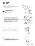
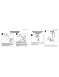
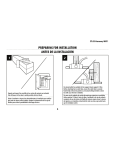
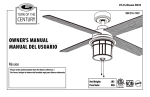
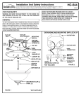
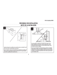
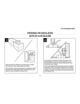
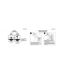
INSTALLATION
INSTALACIÓN
1
Unpack and inspect fan carefully to be certain all
contents are included.
Quite el envoltorio e inspeccione detenidamente el ventilador para verificar que todas las piezas estén incluidas.
Turn off power at fuse box to avoid possible
electrical shock.
Apague la alimentación en la caja de
fusibles para evitar la posibilidad de descarga eléctrica.
2
Use metal outlet box suitable for fan support (must support 35 lbs).
Before attaching fan to outlet box, ensure the outlet box is securely
fastened by at least two points to a structural ceiling member (a loose
box will cause the fan to wobble).
Use una caja de embutir de metal adecuada para soportar un ventilador
(debe soportar 35 libras). Antes de fijar el ventilador a la caja de embutir
asegúrese de que la misma esté fijada de manera segura en por lo menos
dos puntos a un miembro estructural del cielo raso (una caja suelta haría
que el ventilador oscile).
Install mounting bracket (G) to outlet box in ceiling using the screws and
washers provided with the outlet box.
3
Instale el soporte de montaje (G) a la caja de embutir del cielorraso con la
tornillería suministrada con la caja de embutir.
E
4
Remove clamp pin (O) and cross pin (P) from downrod (J).
Quite el pasador tipo prensa (O) desde el pasador transversal (P) de la vara (J).
J
O
6
P
ETL-ES-Sparta-WH10
Choose a mounting option / Elija una opción de montaje:
5
6
NORMAL DOWNROD INSTALLATION - If installing
downrod supplied with fan, proceed to step 6.
EXTENDED DOWNROD INSTALLATION - If installing
with longer downrod than supplied with fan,
proceed to step 8.
NORMAL -Si instala la varilla vertical incluida con el
ventilador, proceda al paso 6.
OPCIÓN CON VARILLA VERTICAL MÁS LARGA - Si
instala una varilla vertical más larga que la que se incluye
con el ventilador, proceda al paso 8.
NORMAL
DOWNROD
INSTALLATION
EXTENDED
DOWNROD
INSTALLATION
NORMAL
OPCIÓN CON
VARILLA VERTICAL
MÁS LARGA
Place downrod assembly (J) into canopy (F), canopy cover ring (H)
and coupling cover (R). Feed motor wires though the downrod assembly (J).
F
Coloque el conjunto de la varilla vertical (J) dentro del dosel (F), el anillo de
la cubierta del dosel (H) y la cubierta del acoplamiento (R). Pase los cables del motor
a través del conjunto de la varilla vertical (J).
H
R
J
7
Loosen set screws (T) in downrod coupling (K). Insert downrod (J) into
downrod coupling (K). Make sure to align hole in downrod (J) with
the hole in downrod coupling (K). Install coupling cross pin (P) through
coupling and downrod. Insert clamp pin (O) into cross pin until it snaps
into place. Tighten set screws (T) in coupling. PROCEED TO STEP 10.
J
Afloje los tornillos prisioneros (T) en el acoplador (K). Inserte la vara (J) en
el acoplador de vara (K). Asegúrese de alinear el orificio de la vara (J) con
el orificio del acoplador (K). Instale el pasador transversal del acoplador (P)
a través del acoplador y la vara. Inserte el pasador tipo prensa (O) en
el pasador transversal hasta que trabe en su lugar. Apriete los tornillos
prisioneros (T) en el acoplador. PROCEDA AL PASO 10.
O
K
P
T
I
8
Q
Loosen downrod ball (I) from downrod (J) by removing set screw (S).
Slide downrod ball (I) off of downrod and remove pin (Q).
Afloje la esfera de la varilla vertical (I) de la varilla vertical (J) quitando el
tornillo (S). Deslice la esfera de la varilla vertical (I) hasta separarla de la varilla
vertical y quite el pasador (Q).
S
J
ETL-ES-Sparta-WH10
I
7
Re-install pin (Q) into extended downrod, and slide downrod ball (I) up to the top of
the downrod. Re-install set screw (S) to secure ball to downrod. Note: Some
extended downrods have a pre-drilled set-screw hole. If a pre-drilled hole is present
in the extended downrod, tighten the set screw into the pre-drilled hole in the
extended downrod. If no pre-drilled hole exists in the extended downrod, tighten the
set screw against the downrod to secure the downrod ball. PROCEED TO STEP 6.
9
Q
I
Vuelva a instalar el pasador (Q) en la varilla vertical más larga y deslice la esfera
de la varilla (I) hasta el extremo superior de la misma. Vuelva a insertar el tornillo
de fijación (S) para asegurar la esfera a la varilla vertical. Nota: Algunas varillas verticales
más largas tienen un agujero previamente perforado para el tornillo. Si la varilla vertical
más larga tiene un agujero previamente perforado, ajuste el tornillo en el agujero
previamente perforado de la varilla vertical más larga. Si la varilla vertical más larga no
tiene un agujero previamente perforado, ajuste el tornillo sobre la varilla vertical para
asegurar la esfera de la misma. PROCEDA AL PASO 6.
S
G
I
10
11
8
Carefully lift fan assembly onto mounting bracket (G). Rotate fan until notch
on downrod ball (I) engages the ridge on the mounting bracket (G). This will
allow for hands free wiring. See following step for wiring instructions.
G
Levante con cuidado el conjunto del ventilador hasta el soporte de montaje (G).
Gire el ventilador hasta que la muesca de la bola de la varilla vertical (I) calce
sobre la saliente del soporte de montaje (G). De este modo, tendrá las dos manos
libres para hacer el cableado. Vea el siguiente paso para las instrucciones
de cableado.
Make wiring connections from the house and the fan
to the remote receiver (N) as shown. Connect using wire
nuts (BB) (provided). Make sure that all exposed wiring is
secured inside wire nuts. Refer to Point 3 of Safety Tips
on page 2.
BB
N
Haga las conexiones de cableado del alojamiento y el
ventilador al receptor remoto (N) como se indica. Utilice
las tuercas para cables (BB) incluidas. Asegúrese de que todos
los cables expuestos estén asegurados dentro de los
conectores tipo tuerca para cables. Refiérase al punto 3 de
la información sobre seguridad en la página 2.
ETL-ES-Sparta-WH10
12
This remote control unit is equipped with 16 code combinations to
prevent possible interference from or to other remote units. The frequency
switches on your receiver (N) and transmitter (M) have been preset at the
factory. Please recheck to make sure the switches on transmitter (M) and
receiver (N) are set to the same position, any combination of settings will
operate the fan as long as the transmitter and receiver are set to the same
position.
Note: Install one 6F22 (9V) battery by removing battery cover on back
of transmitter, installing battery, and replacing battery cover.
M
N
Esta unidad de control remoto está equipada con 16 códigos de combinación
para prevenir posibles interferencias con otras unidades de control remoto.
Los interruptores de frecuencia en su receptor (N) y transmisor (M) han sido
programados en fábrica. Por favor verifique que los interruptores en
el transmisor (M) y el receptor (N) estén en la misma posición, cualquier
combinación hará funcionar el ventilador siempre y cuando el transmisor y
el receptor estén en la misma posición.
Nota: Para instalar la pila 6F22 (9V) quite la cubierta del receptáculo
para la pila en la parte posterior del transmisor, instale la pila y vuelva
a colocar la cubierta.
G
13
14
Once wiring step has been completed, slide the wired
remote receiver in between the bracket (G) and the top
of the downrod ball (I).
Una vez completado el cableado, deslice el receptor
remoto entre la pieza de fijación (G) y la parte superior
de la esfera de la varilla vertical (I).
I
G
Align the keyholes on the canopy (F) with the protruding
screw heads (U) from the mounting bracket (G). Lift the
canopy up and rotate clockwise until the screwheads
engage the keyslots fully.
Alinee los orificios del escudete (F) con las cabezas
de tornillo sobresalientes (U) del soporte de montaje (G).
Levante el escudete y gírelo en dirección de las
manecillas del reloj hasta que las cabezas de tornillo
calcen por completo con los chaveteros.
U
F
U
ETL-ES-Sparta-WH10
9
15
The inside canopy cover ring (H) has two keyhole slots that allow it
to be mounted onto the screw heads on the two protruding screws
from the mounting bracket. Slide the canopy cover ring up the
downrod, and allow the two protruding screw heads from the
mounting bracket to go into the keyhole slots on the canopy cover
ring. Once engaged, twist the canopy cover ring to lock it onto the
screw heads.
Note: Some adjustment of the screws from the mounting bracket
may be necessary to allow the canopy cover ring to attach to the
screw heads in the appropriate manner:
1. Loosening of the screw heads may be necessary to allow the
canopy cover ring to fit onto the screws from the mounting
bracket.
2. If the canopy is still loose after installing the canopy cover ring,
the canopy cover ring may need to be removed and the
mounting bracket screws tightened slightly to allow a more
snug fit of the canopy, when the canopy cover ring is installed.
H
La cubierta interior para el anillo (H) del dosel tiene dos ranuras que
permiten montarla en las cabezas de los dos tornillos que sobresalen
del soporte de montaje. Deslice la cubierta el anillo del escudete hacia
arriba por la varilla y permita que las dos cabezas sobresalientes de
los tornillos penetren en las ranuras de la cubierta del escudete. Una
vez penentren, gire la cubierta del escudete para trabar las cabezas
de los tornillos en la parte más estrecha.
Nota: Puede ser necesario ajustar los tornillos del soporte de montaje
para permitir que la cubierta del escudete se acople a las cabezas de
los tornillos de manera apropiada.
1. Afloje los tornillos si es necesario para permitir que la cubierta
del escudete pase sobre los tornillos del soporte de montaje.
2. Si el escudete aún está suelto después de instalar la cubierta el anillo
del escudete, puede que sea necesario retirar la cubierta el anillo
del escudete y apretar ligeramente los tornillos del soporte de
montaje para lograr un ajuste más preciso del escudete una vez
instalada la cubierta el anillo del escudete.
A
16
Remove the flywheel (B) from the motor (A) by removing
the screws (W). Save the screws (W) for use in step 18.
Quite la rueda (B) del motor (A) quitando los tornillos (W).
Guárdelos los tornillos (W) para usarlos en el paso 18.
W
B
10
ETL-ES-Sparta-WH10
B
C
17
Insert the blade (C) through the slot on the flywheel (B). Make
sure blade holes and holes on the flywheel are aligned. Secure
the blade to the flywheel using blade screws (V) and metal
washers (AA) provided. Repeat this step for remaining blade.
Tighten screws securely.
V
Inserte la paleta (C) a través de la ranura en la rueda (B). Asegúrese
de que los agujeros de la paleta y los de la rueda estén alineados.
Fije la paleta a la rueda usando los tornillos para la paleta (V) y
las arandelas de metal (AA) incluidos. Repita este paso para el aspa
restante. Apriete completamente los tornillos.
AA
A
18
Insert the wires from the motor (A) through the
hole in the flywheel (B). Attach the flywheel (B) to
the motor (A) using the screws (W) removed in step
16. Tighten screws securely.
Inserte los alambres del motor (A) a través del orificio
en la rueda (B). Fije la rueda (B) al motor (A) usando los
tornillos que extrajo en el paso 16.. Apriete
completamente los tornillos.
B
W
19
Remove one of the screws (X) on the light kit plate (L),
and loosen, (do not remove) the other two.
Extraiga uno de los tornillos (X) de la placa del juego de
luces (L) y afloje los otros dos sin sacarlos del todo.
Χ
L
ETL-ES-Sparta-WH10
11
A
20
Connect the wire plugs from the motor (A) to the wire
plugs from the light kit (D), white to white, and black to
black.
Conecte los conectores para cables del motor (A) a
los conectores para cables del juego de luces (D) blanco a
blanco y negro a negro.
D
Attach the light kit (D) to the light kit plate by placing the
keyslot holes from the light kit onto the two
protruding screw heads from the light kit plate. Twist
the light kit until the screwheads engage the keyslots.
21
Install the screw (X) removed from the light kit plate (step
19) into the closed hole in the light kit. Tighten all
screws to complete attachment of the light kit.
Fije el juego de luces (D) a la placa del juego de luces del
mismo colocando las ranuras bocallaves del juego de luces
sobre las cabezas de los dos tornillos que sobresalen de la
placa del juego de luces correspondiente. Gire el juego de
luces hasta que las cabezas de los tornillos se enganchen
en las ranuras bocallaves.
Inserte el tornillo (X) que extrajo de la placa del juego de
luces (en el paso 19) en el orificio cerrado del juego de luces.
Ajuste todos los tornillos para completar la instalación del
juego de luces.
12
D
Χ
ETL-ES-Sparta-WH10
Install E11 base, max 100W bulb (CC) (included).
Caution: Do not touch glass part of bulbs with bare hands.
22
Instale las bombilla (CC) de base E11 de un máximo de 100
vatios (se incluyen).
Advertencia: No toque la parte de vidrio de las lámparas
directamente con las manos.
CC
23
Locate the indentations on the neck of the glass (E)
and align with the protrusions from the light kit (D).
Lift the glass up allowing the protrusions to engage the
indentations on the glass, and twist the glass clockwise
to lock into place.
Localice las marcas en el cuello de la pantalla de vidrio (E)
y alinéelas con las protuberancias del juego de luces (D).
Levante la pantalla permitiendo que las protuberancias
calcen en las marcas de la pantalla de vidrio y gire
la pantalla en sentido horario para asegurarla en su sitio.
D
E
Note: After glass installation, confirm the notch on downrod ball
(I) is engaged into the ridge on the mounting bracket (G).
Nota: Después de la instalación de vidrio, confirmar la muesca de
la bola de la varilla vertical (I) calce sobre la saliente del soporte
de montaje (G).
ETL-ES-Sparta-WH10
I
G
13
24
Mount wall bracket to the wall using screws provided.
Instale el soporte de pared sobre la pared con los
tornillos incluidos.
Place the transmitter into the mounted holder.
25
Coloque el transmisor en el soporte montado.
Remote Control Operation
1. Fan Control– press and release. The remote control operates the fan
speed as follows: 1 - high; 2 - medium; 3 – low; 0 - off.
2. Light On/Off – press and release light button.
3. Light Dimmer – continuous pressure on the light button dims light in a
continuous cycle from light to dark, or dark to light.
Operación con control remoto
1. Control del ventilador: presione y suelte. El control remoto controla
las velocidades del ventilador de la siguiente manera:
1 - alta; 2 – mediana; 3 - baja; 0 - apagado.
2. Luz encendida/apagada –presionar y soltar el botón de luz.
3. Conmutador de intensidad – al presionar continuamente el botón de luz,
esta última conmuta en un ciclo continuo de más claro a más oscuro o
de más oscuro a más claro.
14
ETL-ES-Sparta-WH10
NOTICE
This ‘Energy Policy Act 2005’ compliant fan includes a device that limits the total wattage of its light fixture to 190 watts.
By installing a combination of light bulbs that exceeds 190 watts or if an electrical surge causes the wattage
to exceed 190 watts, the light fixture will either dim the lights to 190 watts or will automatically turn off.
To restore the light levels, make sure the total wattage of the light bulbs does not exceed
190 watts and follow the applicable directions below:
For fans with Pull Chains:
Pull the light fixture’s pull chain two times to reset the light fixture. If the power to your fan is controlled
by a toggle wall switch, it may be necessary to turn the power off and back on at the wall switch.
For fans with Wall Controls:
Press the light button on the wall control “off” and “on” once to reset the light fixture.
For fans with Remote Controls:
If you verify the wattage and the lights do not turn on, press the light button on the
remote control twice to reset the light fixture.
NOTE: If the procedures above do not reset the lights, turn off the main power source,
located at the breaker panel or box, and then turn it on again.
AVISO
Este ventilador, que cumple con las exigencias del 'Energy Policy Act 2005', incluye un accesorio
que limita el vataje total de su lámpara a 190 vatios.
Si usted instala una combinación de bombillas que sobrepasen los 190 vatios o si un sobrevoltaje hace que el voltaje sea
superior a 190 vatios, la lámpara regulará la intensidad a 190 vatios o se apagará.
Para restablecer el nivel de luminosidad, asegúrese que el vataje total de las bombillas no sobrepase
los 190 vatios y siga las indicaciones aplicables a continuación:
Para ventiladores con Cadenilla de tiro:
Jale la cadenilla de la lámpara dos veces para reiniciarla. Si la energía de su ventilador se controla con un interruptor
en la pared, puede ser necesario apagar el interruptor y luego encenderlo.
Para ventiladores con Control de pared:
Presione el botón en la pared una vez para apagar y una vez para encender, para así reiniciar la lámpara.
Para ventiladores con Control remoto:
Si verifica el vataje y la luz no enciende, presione el botón para la luz en el control remoto dos veces para reiniciar la lámpara.
NOTA: Si los procedimientos mencionados no reinician la lámpara, desconecte la fuente principal de energía,
ubicada en el panel o caja de interruptor, y vuélvala a conectar.
ETL-ES-Sparta-WH10
15