1
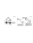
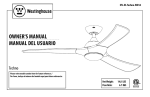
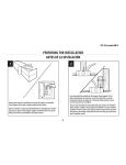
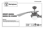
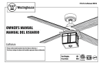
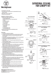
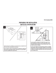
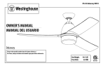
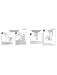
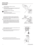
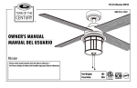
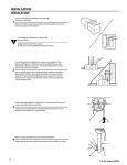
ETL-ES-Techno-WH14
ETL-ES-Techno-WH14
PREPARING FOR INSTALLATION
ANTES DE LA INSTALACIÓN
FEATURES
CARACTERÍSTICAS
DOWNROD
INSTALLATION
VAULTED CEILING
INSTALLATION
INSTALACIÓN CON
VARILLA VERTICAL
NSTALACIÓN PARA
CIELORRASOS ABOVEDADOS
1
2
Unpack and inspect fan carefully to be certain all contents are included.
Turn off power at fuse box to avoid possible electrical shock.
Use metal outlet box suitable for fan support (must support 35 lbs).
Before attaching fan to outlet box, ensure the outlet box is securely
fastened by at least two points to a structural ceiling member (a loose
box will cause the fan to wobble).
Use una caja de embutir de metal adecuada para soportar un ventilador
(debe soportar 35 libras). Antes de fijar el ventilador a la caja de embutir
asegúrese de que la misma esté fijada de manera segura en por lo menos
dos puntos a un miembro estructural del cielo raso (una caja suelta haría
que el ventilador oscile).
Note: For pitched ceiling installation, please
refer to westinghouselighting.com for specially
designed canopy kit options.
Nota: Para instalación en cielo rasos inclinados,
visite westinghouselighting.com para obtener
información.
May require a longer downrod
(sold separately)
For normal ceilings
Para cielorrasos normales
Podría requerir una varilla vertical más larga
(se vende por separado)
4
Quite el envoltorio e inspeccione detenidamente el ventilador para verificar
que todas las piezas estén incluidas. Apague la alimentación en la caja de
fusibles para evitar la posibilidad de descarga eléctrica.
5
ETL-ES-Techno-WH14
MOUNTING BRACKET INSTALLATION
INSTALACIÓN CON SOPORTE DE MONTAJE
ETL-ES-Techno-WH14
NORMAL DOWNROD OPTION
OPCIÓN CON VARILLA VERTICAL PARA CIELORRASO NORMAL
MOUNTING OPTIONS
OPCIONES DE MONTAJE
3
4
Choose a MOUNTING OPTION
Elija una OPCIÓN DE MONTAJE
5
6
1
NORMAL DOWNROD OPTION
If installing downrod supplied with fan, proceed to page 7, step#5.
OPCIÓN CON VARILLA VERTICAL PARA CIELORRASO NORMAL
Si instala la varilla vertical incluida con el ventilador,
proceda a la página 7, paso 5.
2
3
3
EXTENDED DOWNROD OPTION
If installing with longer downrod than supplied with fan, proceed to page 9, step#8.
4
OPCIÓN CON VARILLA VERTICAL MÁS LARGA
Si instala una varilla vertical más larga que la que se incluye con el
ventilador, proceda a la página 9, paso 8.
Install mounting bracket to outlet box in ceiling using the screws and
washers provided with the outlet box.
Instale el soporte de montaje a la caja de embutir del cielorraso con la
tornillería suministrada con la caja de embutir.
1
Place downrod assembly into canopy (1), canopy cover ring (2) and coupling cover (3).
Feed motor wires through the downrod assembly (4).
2
Coloque el conjunto de la varilla vertical (1) dentro del dosel (1), el anillo de la cubierta
del dosel (2) y la cubierta del acoplamiento (3). Pase los cables del motor a través del
conjunto de la varilla vertical (4).
Remove clamp pin (1) and cross pin (2) from downrod (3).
Quite el pasador tipo prensa (1) desde el pasador transversal (2) de la vara (3).
6
7
ETL-ES-Techno-WH14
ETL-ES-Techno-WH14
NORMAL DOWNROD OPTION
OPCIÓN CON VARILLA VERTICAL PARA CIELORRASO NORMAL
7
EXTENDED DOWNROD OPTION
OPCIÓN CON VARILLA VERTICAL MÁS LARGA
9
8
4
3
2
1
3
5
2
1
1
2
Loosen set screws (1) in downrod coupling (2). Insert downrod into downrod coupling. Make sure to align hole in downrod with the hole in downrod coupling. Install coupling cross pin (3)
through coupling and downrod. Insert clamp pin (4) into cross pin until it snaps into place. Tighten set screws (1) in coupling. Slide coupling cover (5) over the downrod coupling. PROCEED
TO PAGE 11, STEP 11.
Afloje los tornillos prisioneros (1) en el acoplador (2). Asegúrese de que el orificio de la varilla vertical y el del acoplamiento de la varilla vertical estén alineados. Instale el pasador transversal
(3) pasándolo por el acoplamiento y la varilla vertical. Inserte el pasador de fijación (4) en el pasador transversal hasta que escuche un chasquido que indique que está en la posición adecuada. Ajuste los tornillos de fijación (1) en el acoplamiento. Deslice la cubierta del acoplamiento (5) sobre el acoplamiento de la varilla vertical. PASEZ À LA PAGE 11,
ÉTA PE 11.
8
Loosen downrod ball (1) from downrod (2) by removing set screw (3).
Slide downrod ball (1) off of downrod and remove pin (2).
Afloje la esfera de la varilla vertical (1) de la varilla vertical (2)
quitando el tornillo (3).
Deslice la esfera de la varilla vertical (1) hasta separarla de la
varilla vertical y quite el pasador (2).
9
ETL-ES-Techno-WH14
ETL-ES-Techno-WH14
EXTENDED DOWNROD OPTION
OPCIÓN CON VARILLA VERTICAL MÁS LARGA
BLADE INSTALLATION
INSTALACIÓN DE LAS PALETAS
11
10
12
3
4
3
1
4
2
Re-install pin into extended downrod, and slide downrod ball up to the top of the downrod. Re-install set screw to secure ball to downrod. Note: Some extended downrods have
a pre-drilled set-screw hole. If a pre-drilled hole is present in the extended downrod, tighten the set screw into the pre-drilled hole in the extended downrod. If no pre-drilled hole
exists in the extended downrod, tighten the set screw against the downrod to secure the downrod ball. PROCEED TO PAGE #7, STEP 5.
Vuelva a instalar el pasador en la varilla vertical más larga y deslice la esfera de la varilla hasta el extremo superior de la misma. Vuelva a insertar el tornillo de fijación para asegurar
la esfera a la varilla vertical. Nota: Algunas varillas verticales más largas tienen un agujero previamente perforado para el tornillo. Si la varilla vertical más larga tiene un agujero
previamente perforado, ajuste el tornillo en el agujeropreviamente perforado de la varilla vertical más larga. Si la varilla vertical más larga no tiene un agujero
previamente perforado, ajuste el tornillo sobre la varilla vertical para asegurar la esfera de la misma. PASEZ À LA PAGE #7, ÉTA PE 5.
10
Place fan body with down rod pointing downward and motor positioned toward
ceiling. Attach the fan blade bracket assembly onto the motor, line up the holes
in the blade bracket with the holes in the motor (marked A-A, B-B. C-C), secure the
blade bracket to the motor with motor screws provided.
Attach blades (1) to the blade bracket (2) using the blade screws (3) and
washers (4)
Usando los tornillos (3) y arandelas (4) conecte las abrazaderas de aspa a
las aspas (1).
Volteas el ventilador par que la varilla este mirando hacia el piso y el motor hacia
el techo. Coloque el asemblaje de las abrazaderas de aspa al motor y alinea sus
agujeros con los agujeros del motor (marcado A-A, B-B, C-C), fije las abrazaderas
de aspa al motor usando los tornillos incluidos.
11
ETL-ES-Techno-WH14
ETL-ES-Techno-WH14
WIRING OPTIONS
OPCIÓN DE CABLEADO
MOUNTING
MONTAJE
14
13
This remote control unit is equipped with 16 code combinations to prevent possible interference from or to other remote units. The frequency switches on your receiver and transmitter
have been preset at the factory. Please recheck to make sure the switches on transmitter and receiver are set to the same position, any combination of settings will operate the fan as long
as the transmitter and receiver are set to the same position.
Carefully lift fan assembly onto mounting bracket. Rotate fan until notch on downrod ball (1) engages the ridge on the mounting bracket (2). This will allow for hands free wiring.
Levante con cuidado el conjunto del ventilador hasta el soporte de montaje. Gire el ventilador hasta que la muesca de la bola de la varilla vertical (1) calce sobre la saliente del soporte
de montaje (2). De este modo, tendrá las dos manos libres para hacer el cableado.
Esta unidad de control remoto está equipada con 16 códigos de combinación para prevenir posibles interferencias con otras unidades de control remoto. Los interruptores de frecuencia en
su receptor y transmisor han sido programados en fábrica. Por favor verifique que los interruptores en el transmisor y el receptor estén en la misma posición, cualquier combinación hará
funcionar el ventilador siempre y cuando el transmisor y el receptor estén en la misma posición.
12
13
ETL-ES-Techno-WH14
ETL-ES-Techno-WH14
SECURE TO CEILING
ASEGURE EL VENTILADOR AL CIELORRASO
WIRING OPTIONS
OPCIÓN DE CABLEADO
16
15
17
Make wiring connections from the house and the motor to the remote receiver as shown
above. Connect using wire nuts (provided).
Haga las conexiones de cableado del alojamiento y el motor al receptor remoto como se
indica más arriba. Utilice las tuercas para cables incluidas.
14
Once wiring step has been completed, slide the wired remote receiver in between the
mounting bracket and the top of the downrod ball for downrod fans.
Loosen the 2 screws on the bottom of mounting bracket. (do not remove) Raise the canopy up and align the keyholes on the bottom of the canopy with the 2 screws on
the bottom of mounting bracket. Rotate the canopy until both screws from the mounting bracket drop into the slot recesses. Tighten screws securely.
Para los ventiladores con vara de extensión, al terminar la instalación de los alambres,
deslice el receptor remoto alámbrico entre el soporte de montaje y la parte superior de
la esfera de la vara.
Afloje los 2 tornillos de la parte inferior del soporte de montaje (no los extraiga completamente). Suba el dosel y alinee las bocallaves de la parte inferior del dosel con
los 2 tornillos de la parte inferior del soporte de montaje. Gire el dosel hasta que ambos tornillos del soporte de montaje caigan dentro de las ranuras. Apriete los tornillos asegurándolos.
15
ETL-ES-Techno-WH14
ETL-ES-Techno-WH14
LIGHT FIXTURE INSTALLATION
INSTALACIÓN DEL ARTEFACTO LUMINOSO
18
19
1
The inside canopy cover ring (1) has two keyhole slots that allow it to be mounted onto the screw heads on the two protruding screws from the mounting bracket. Slide the canopy cover ring
up the downrod, and allow the two protruding screw heads from the mounting bracket to go into the keyhole slots on the canopy cover ring. Once engaged, twist the canopy cover ring to
lock it onto the screw heads. Note: Some adjustment of the screws from the mounting bracket may be necessary to allow the canopy cover ring to attach to the screw heads in the appropriate
manner:
1. Loosening of the screw heads may be necessary to allow the canopy cover ring to fit onto the screws from the mounting bracket.
2. If the canopy is still loose after installing the canopy cover ring, the canopy cover ring may need to be removed and the mounting bracket screws tightened slightly to allow a more snug fit
of the canopy, when the canopy cover ring is installed.
La cubierta interior para el anillo (1) del dosel tiene dos ranuras que permiten montarla en las cabezas de los dos tornillos que sobresalen del soporte de montaje. Deslice la cubierta el anillo
del escudete hacia arriba por la varilla y permita que las dos cabezas sobresalientes de los tornillos penetren en las ranuras de la cubierta del escudete. Una vez penentren, gire la cubierta del
escudete para trabar las cabezas de los tornillos en la parte más estrecha. Nota: Puede ser necesario ajustar los tornillos del soporte de montaje para permitir que la cubierta del escudete se
acople a las cabezas de los tornillos de manera apropiada.
1. Afloje los tornillos si es necesario para permitir que la cubierta del escudete pase sobre los tornillos del soporte de montaje.
2. Si el escudete aún está suelto después de instalar la cubierta el anillo del escudete, puede que sea necesario retirar la cubierta el anillo del escudete y apretar ligeramente los tornillos del
soporte de montaje para lograr un ajuste más preciso del escudete una vez instalada la cubierta el anillo del escudete.
16
2
3
1
Remove one of the screws (1) on the light kit plate support (3), and loosen, (do not remove) the other two (2).
Quite uno de los tornillos (1) del soporte de la placa del juego de luces (3) y suelte (sin quitar) los otros dos (2).
17
ETL-ES-Techno-WH14
ETL-ES-Techno-WH14
LIGHT FIXTURE INSTALLATION
INSTALACIÓN DEL ARTEFACTO LUMINOSO
20
LIGHT FIXTURE INSTALLATION
INSTALACIÓN DEL ARTEFACTO LUMINOSO
21
1
1
2
2
Attach the light kit plate (2) to the light kit plate support (1) by placing the keyslot holes from the light kit plate onto the two protruding screw heads from the light kit plate
support. Twist the light kit plate clockwise until the screwheads engage the keyslots. Install the screw removed from light kit plate support (step#19) into the closed hole in
the light kit plate. Tighten all screws to complete attachment of the light kit plate.
Remove one of the 3 screws from the light kit plate (1), and loosen (do not remove) the other two. Connect the wires from motor to the wires from the light kit (2) by using
the 2-pin molex plug. Attach the light kit (2) onto the light kit plate (1) by placing the key slot holes in the light kit (2) onto the two protruding screw heads on the light
kit plate (1). Twist the light kit (2) until the screw heads engage the key slots. Install the screw removed from the light kit plate (1) into the closed hole in the light kit (2).
Tighten all screws to complete the attachment of the light kit (2).
Fije la placa del juego de luces (2) al soporte de la placa del juego de luces (1) colocando los orificios de chavetero de la placa del juego de luces en las dos cabezas de tornillo
sobresalientes del soporte de la placa del juego de luces. Gire la placa del juego de luces en dirección de las manecillas del reloj hasta que las cabezas de tornillo calcen con
los chaveteros. Instale el tornillo que quitó del soporte de la placa del juego de luces (paso 19) en el orificio cerrado de la placa del juego de luces. Apriete todos los tornillos
para poner fin a la fijación de la placa del juego de luces.
Quite uno de los 3 tornillos de la placa del juego de luces (1) y afloje los otros dos (sin sacarlos del todo). Conecte los cables del motor a los cables del juego de luces (2) utilizando el conector Molex de 2 pines. Fije el juego de luces (2) a la placa del juego de luces (1) colocando las ranuras del juego de luces (2) sobre las dos cabezas de los tornillos que sobresalen de la placa del juego de luces (1). Gire el juego de luces (2) hasta que las cabezas de los tornillos enganchen en las ranuras. Coloque el tornillo que extrajo
de la placa del juego de luces (1) en el orificio cerrado del juego de luces (2). Ajuste todos los tornillos para completar la instalación del juego de luces (2).
18
19
ETL-ES-Techno-WH14
ETL-ES-Techno-WH14
23
22
OFF
HIGH
MED
M.LOW
LOW
LIGHT
Locate the indentations on the neck of the glass and align with the protrusions on the inside of the light kit plate. Lift the glass up allowing the protrusions to engage the indentations of the
glass, and twist the glass clockwise to lock into place.
Mount the transmitter holder onto the wall using screws provided. Place the transmitter into the holder.
Localice las marcas en el cuello de la pantalla de vidrio y alinéelas con las protuberancias del la placa de juego de luces. Levante la pantalla permitiendo que las protuberancias calcen en las
marcas de la pantalla de vidrio y gire la pantalla en sentido horario para asegurarla en su sitio.
Monte el soporte para el transmisor a la pared usando los tornillos incluidos. Coloque el transmisor en el soporte.
20
21
ETL-ES-Techno-WH14
ETL-ES-Techno-WH14
OPERATION & MAINTENANCE
24
Operation
OFF
Speed settings for warm or cool weather depend on factors such as room size, ceiling height, number of fans and so on. The slide switch controls direction, forward or reverse.
HIGH
Warm weather/down position - (Forward) Fan turns counterclockwise direction. A downward air flow creates a cooling effect as shown in illustration A. This allows you to set your air
conditioner on a higher temperature setting without affecting your comfort.
MED
Remote Control Operation
1. Fan Control– press and release. The remote control
operates the fan speed as follows: OFF – off; HIGH - high;
MED - medium high; M.LOW - medium; LOW - low;
2. Light On/Off – press and release light button.
M.LOW
LOW
LIGHT
Operación con control remoto
1. Control del ventilador: presione y suelte. El control remoto
controla las velocidades del ventilador de la siguiente
manera: OFF - apagado; HIGH - alta; MED - media alta;
M.LOW - media; LOW – baja;
2. Luz encendida/apagada –presionar y soltar el botón de luz.
22
Cool weather/up position - (Reverse) Fan turns clockwise direction. An upward airflow moves warm air off the ceiling area as shown in illustration B. This allows you to set your heating unit
on a lower setting without affecting your comfort.
NOTE: Turn off and wait for fan to stop before changing the setting of the forward/reverse slide switch.
Maintenance
1. Because of the fan’s natural movement, some connections may become loose. Check the support connections, brackets, and blade
attachments twice a year. Make sure they are secure.
2. Clean your fan periodically to help maintain its new appearance over the years. Do not use water when cleaning. This could damage
the motor, or the wood, or possibly cause electrical shock.
3. Use only a soft brush or lint-free cloth to avoid scratching the finish. The plating is sealed with a lacquer coating to minimize
discoloration or tarnishing.
4. There is no need to oil your fan. The motor has permanently lubricated bearings.
23