1
www.HunterFan.com
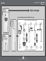
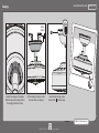
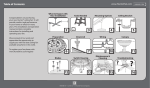
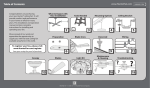
What to Expect with Your Installation
Read and Save These Instructions
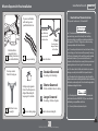
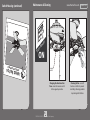
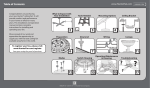
If you are unfamiliar
with wiring, use a
qualified electrician.
This product conforms to UL Standard 507.
WARNINGS
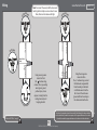
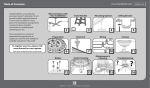
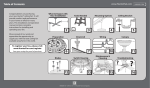
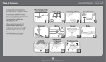
30 inches
from blade tip
to nearest wall
or obstruction
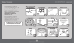
Must be able to
secure the fan to
building structure or
fan-rated outlet box
Know your wiring
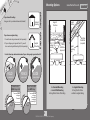
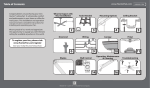
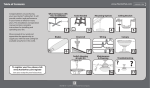
Ceiling angles greater
than 34° will require an
Angled Mounting Kit.
See page 4 for details.
Check box to see
fan weight
7 feet
from bottom
edge of blade
to the floor
You may need a
friend to help you.
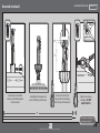
Assess location
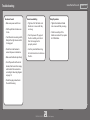
w.1 - To reduce the risk of fire, electrical shock, or
personal injury, mount fan directly from building
structure and/or an outlet box marked acceptable for
fan support of 70 lbs (31.8 kg) and use the mounting
screws provided with the outlet box.
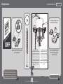
w.2 - To avoid possible electrical shock, before installing
or servicing your fan, disconnect the power by turning
off the circuit breakers to the outlet box and associated
wall switch location. If you cannot lock the circuit
breakers in the off position, securely fasten a prominent
warning device, such as a tag, to the service panel.
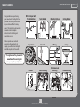
1
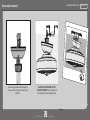
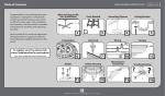
Standard Downrod
w.3 - To reduce the risk of fire, electrical shock, or motor
damage, use only Hunter Solid State Speed Controls.
2
Shorter Downrod
w.4 - To reduce the risk of personal injury, do not bend the
blade brackets when installing the blade brackets, balancing
the blades, or cleaning the fan. Do not insert foreign objects
in between rotating fan blades.
3
for ceilings 8-10 feet high
for fans installed close to ceiling
Longer Downrod
for ceilings 10 feet or higher
CAUTIONS
c.1 - All wiring must be in accordance with national and
local electrical codes ANSI/NFPA 70. If you are unfamiliar
with wiring, use a qualified electrician.
c.2 - Use only Hunter replacement parts.
Assess ceiling angle
1.888.830.1326
Select a downrod length
2
M3526-01 • 05/02/13 • © Hunter Fan Company