Transcript
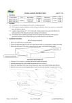
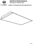
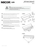
T3 TROFFER ASSEMBLY
INSTALLATION INSTRUCTIONS
Model(s): T3C-14-MV-35
T3C-14-MV-40
T3C-14-MV-50
T3C-22-MV-35
T3C-22-MV-40
T3C-22-MV-50
T3C-24-MV-35
T3C-24-MV-40
T3C-24-MV-50
The installation must only be performed by a licensed electrician.
To prevent death, injury or damage to property, this product must be installed in accordance to
National Electrical Code (NFPA70) in the US or Canadian Electrical Code (CSA 22.1) in Canada.
Disconnect power before installing the product or servicing it.
MIN. 90°C SUPPLY CONDUCTORS
1
for defects due to shipping.
2
3
4
5
state and local codes.
White
Black
Junction Box
7
Reattach cover of Junction Box and secure with two screws.
8
Turn power on and verify that the panel is lit.
NICOR, Inc. January 12, 2015 5:26 PM
1-10V (-)
Com
Line
GND
Blue
Red
Blue*
Red
Grey
Purple
1-10V (+)
Connect wiring as shown. Grey and Purple wiring are for 0 - 10V
9
6
*may be black wire with blue tag
Luminaire
Remove cover from Power Supply/Junction Box by removing two
screws.
LED Driver
6
5