1
PROGRESS
LIGHTING
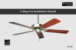
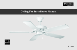
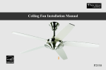
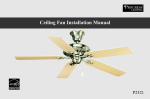
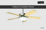
Ceiling Fan Installation Manual
| P2533
30-YEAR LIMITED WARRANTY
Progress Lighting fan motors are warranted to the END USER to be free of electrical
and/or mechanical defects for a period of 30 years from date of sale. Pull
chain switches, reverse switches, capacitors and metal finishes are warranted for a
period of 1 year. Warping of wooden or plastic blades is not covered by this warranty.
The END USER has the option of returning the defective fan to the place of purchase
during the first 30 days for a replacement. After 30 days, the purchaser MUST contact
Progress Lighting for repair or replacement. The END USER also bears the
responsibility for all costs in the removal, shipping and reinstallation of fans or parts
for repair or replacement.
Progress Lighting will not assume liability or responsibility for damages (including
incidental or consequential) caused by the improper installation or operation of the
unit or its component parts, or by the failure of supporting hardware not supplied by
Progress Lighting. This warranty is given in lieu of all other guarantees, whether
expressed or implied, and 1s voided in cases of abuse, misuse or improper handling,
negligence, shipping damage, unauthorized repairs (made or attempted) or unusual
application.
Some states do not allow limitations on how long an implied warranty lasts or the
exclusion or limitations of incidental or consequential damages, so the above
limitations and exclusions may not apply to you. This warranty gives you specific
rights and you may have other rights which vary from state to state.
PROGRESS
LIGHTING
Date Purchased
Store Purchased
UL Model No. P2533
Serial No.
Vendor No. 5523
785247155750
UPC
30-YEAR LIMITED WARRANTY
Safety К) 1
Unpacking Your Fan aaa rr aarara eros 2
Installing YourFan aaa aaa 3
Operating Your Fan aaa 11
Care of Your Fan errar e rr erre rre 12
Troubleshooting aaa aaa 13
SPECI ICaAtIONS | 14
Table of Contents
READ AND SAVE THESE INSTRUCTIONS
To reduce the risk of electric shock, insure electricity has
been turned off at the circuit breaker or fuse box before
beginning.
All wiring must be in accordance with the National
Electrical Code and local electrical codes. Electrical
installation should be performed by a qualified licensed
electrician.
WARNING: To reduce the risk of electrical shock and
fire, do not use this fan with any solid-state fan speed
control device.
CAUTION: To reduce the risk of personal injury, use only
the screws provided with the outlet box.
The outlet box and support structure must be securely
mounted and capable of reliably supporting a minimum of
35 pounds. Use only UL Listed outlet boxes marked “FOR
FAN SUPPORT.”
WARNING
TO REDUCE THE RISK OF FIRE, ELECTRIC SHOCK
OR PERSONAL INJURY, MOUNT FAN TO OUTLET BOX
MARKED ACCEPTABLE FOR FAN SUPPORT WITH THE
SCREWS PROVIDED WITH THE OUTLET BOX.
The fan must be mounted with a minimum of 7 feet
clearance from the trailing edge of the blades to the floor.
Do not operate reversing switch while fan blades are in
motion. Fan must be turned off and blades stopped
before reversing blade direction.
Avoid placing objects in the path of the blades.
1. Safety Rules
9.
10.
11.
12.
To avoid personal injury or damage to the fan and other
items, be cautious when working around or cleaning the
fan.
Do not use water or detergents when cleaning the fan or
fan blades. A dry dust cloth or lightly dampened cloth
will be suitable for most cleaning.
After making electrical connections, spliced conductors
should be turned upward and pushed carefully up into
outlet box. The wires should be spread apart with the
grounded conductor and the equipment-grounding
conductor on one side of the outlet box and ungrounded
conductor on the other side of the outlet box.
Suitable for Use In Wet Locations When Installed
In A GFCI Protected Branch Circuit.
This Fan is suitable for wet location.
WARNING
TO REDUCE THE RISK OF PERSONAL INJURY, DO NOT BEND
THE BLADE BRACKETS (ALSO REFERRED TO AS “FLANGES”)
DURING ASSEMBLY OR AFTER INSTALLATION. DO NOT
INSERT OBJECTS IN THE PATH OF THE BLADES.
IMPORTANT
PLEASE REMOVE RUBBER MOTOR STOPS ON THE BOTTOM OF
THE FAN BEFORE INSTALLING BLADES OR TESTING MOTOR
WARNING
THIS PRODUCT CONTAINS CHEMICALS KNOWN TO THE STATE
OF CALIFORNIA TO CAUSE CANCER, BIRTH DEFECTS AND/OR
OTHER REPRODUCTIVE HARM. THOROUGHLY WASH HANDS
AFTER INSTALLING, HANDLING, CLEANING, OR OTHERWISE
TOUCHING THIS PRODUCT.
Unpack your fan and check the contents. You should have the following items:
FIN —
5
T
— a
—
2
—
3 —
—
. Mounting Plate (located inside
. Fan Motor Assembly 6. Ball/Downrod Assembly (1)
. Canopy with Canopy Ring Attached (with bolt and clevis pin
. Blades (5) pre-attached)
. Blade Bracket Set (5) 7. Upper Switch Housing
(with blade bracket screws 8. Lower Switch Housing
pre-installed) 9. Extra 45-degree Canopy
Bottom Cover
canopy) 10. Motor collar cover
PLEASE REMOVE RUBBER MOTOR STOPS ON THE BOTTOM OF
IMPORTANT
THE FAN BEFORE INSTALLING BLADES OR TESTING MOTOR
о ПА
a. Blade attachment hardware
(15 washer head screws)
b. Mounting hardware (1 rubber gasket,
1 metal gasket, 3 screws &
lock-washers)
c. Electrical hardware & Balancing Kit
(3 plastic wire connectors, 1 pull chain,
blade balancing kit).
Unpacking Your Fan 2.
Tools Required
Phillips screw driver, straight slot
screw driver, adjustable wrench, step
ladder, and wire cutters.
Mounting Options
If there isn't an existing mounting box,
then read the following instructions.
Disconnect the power by removing
fuses or turning off circuit breakers.
Secure the outlet box directly to the
building structure. Use appropriate
fasteners and building materials. The
outlet box and its support must be able
to fully support the moving weight of
the fan (at least 35 Ibs.). Do not use
plastic outlet boxes.
Figures 1, 2, and 3 are examples of
different ways to mount the outlet box.
Figure 1
WARNING
TO REDUCE THE RISK OF FIRE,
ELECTRIC SHOCK, OR OTHER
PERSONAL INJURY, MOUNT FAN ONLY
TO AN OUTLET BOX MARKED
ACCEPTABLE FOR FAN SUPPORT AND
USE THE MOUNTING SCREWS PROVIDED
WITH THE OUTLET BOX. OUTLET BOXES
COMMONLY USED FOR THE SUPPORT
OF LIGHTING FIXTURES MAY NOT BE
ACCEPTABLE FOR FAN SUPPORT AND
MAY NEED TO BE REPLACED. CONSULT
A QUALIFIED ELECTRICIAN IF IN
DOUBT.
«— Provide Strong Support
Ceiling
Recessed » <+——— Mounting
Outlet Box Plate
Figure 3
|| ©
| Outlet box — |
Figure 2
3.Installing Your Fan
Note: You may need a longer
down-rod to maintain proper blade
clearance when installing on a steep,
sloped ceiling. The maximum angle
allowable is 45 degrees. Note: For
mounting angles between 20-45
degrees, please replace the canopy
bottom cover installed on the bottom
of the canopy opening with the extra
45-degree canopy bottom cover
included.
La
Ё ay
и
NIL
J a
Î
Outlet box
Figure 4
To hang your fan where there is an
existing fixture but no ceiling Joist,
you may need an installation hanger
bar as shown in Figure 4 (available at
your Progress Lighting Retailer).
Hanging the Fan
REMEMBER to turn off the power.
Follow the steps below to hang your
fan properly.
NOTE: This ceiling fan is supplied
with two types of hanging assemblies;
the standard ceiling installation using
the ball/ downrod assembly mounting,
and the "close-to-ceiling" mounting.
The "close-to-ceiling" mounting is
recommended in rooms with less than
8-foot ceilings or in areas where
additional space is desired from the
floor to the fan blades. When using
standard downrod installation, the
distance from the ceiling to the bottom
of the fan blades will be approximately
12 inches. The "close-to-ceiling"
installation reduces the distance from
the ceiling to the bottom of the fan
blades to approximately 8 inches.
STANDARD CEILING MOUNTING
Note: For mounting angles between
20-45 degrees, please replace the
canopy bottom cover installed on the
bottom of the canopy opening with
the extra 45-degree canopy bottom
cover included. (See Figure 8)
1. Remove the canopy ring from the
canopy by turning the ring to the right
until it unlocks (Figure5).
Turn Canopy
Ring To Remove
о
= =
Figure 5
4. Route the wires exiting the top of
the fan motor through the decorative
motor collar cover then the canopy
ring. Make sure the slot openings are
on top. Route the wires through the
canopy and then through the
ball/downrod assembly (Figure 7).
5. Loosen, but do not remove, the set
screws on the collar on the top of the
motor housing.
2. Remove the mounting plate from
the canopy by loosening the four
screws on the top of the canopy.
Remove the two non-slotted screws
and loosen the slotted screws. This will
enable you to remove the mounting
late (Figure 6).
Loosen But Do Not Remove
pes. # |
7
Remove
Figure 6
Figure 7 Motor Wires
Ball/Downrod
Assembly
Locked
Position
> Tighten
Screws
3. Remove the hanger pin and
locking pin from downrod assembly.
6. Align the holes at the bottom of
the downrod with holes in the collar on
top of the motor housing (Figure 7).
Carefully insert the hanger pin through
the holes in the collar and downrod. Be
careful not to jam the pin against the
wiring inside the downrod. Insert the
locking pin through the hole near the
end of the hanger pin until it snaps into
its locked position as noted in the
circle inset of Figure 7.
7. Re-tighten the set screws on the
collar on the top of the motor housing.
WARNING
FAILURE TO PROPERLY
LOCKING PIN AS NOTED IN STEP 6
COULD RESULT IN FAN LOOSENING AND
INSTALL
y
№7
Сапору
Bottom Cover
Figure 8
6. Align the three mounting screw holes
on the metal gasket with the holes on
the motor collar at the top of the fan
motor and fasten, using the three screws
and lockwashers provided with metal
gasket.
7. Tighten the three mounting screws
securely.
4. Remove three of the six screws and
lockwashers (every other one) securing
the motor collar to the top of the fan
motor housing (Figure 9).
POSSIBLY FALLING.
CLOSE-TO-CEILING
MOUNTING
1. Remove the canopy ring from the
canopy by turning the ring to the right
until 1t unlocks (Figure 5).
2. Remove the mounting plate from
the canopy by loosening the four
screws on the top of the canopy.
Remove the two non-slotted screws
and loosen the slotted screws. This
will enable you to remove the
mounting plate (Figure 6).
3. Remove the decorative canopy
bottom cover from the canopy by
depressing the three studs (Figure 8).
Screw and
Lockwasher
Motor Collar
Figure 9
5. Route the wires exiting the top of the
fan motor through the plastic gasket,
canopy ring, canopy and the metal
gasket, place the plastic gasket over the
remaining three screws, place the
canopy ring, canopy and the metal
gasket over the motor collar at the top
of the fan motor (Figure 10).
Motor Wires
Screw And
Lockwasher
(3)
Metal
Gasket
Canopy „5
Figure 10
Installing Fan to the
Electrical Box
1.Pass the 120-volt supply wires through the
center hole in the ceiling mounting plate as
shown in Fig.11.
2.Install the ceiling mounting plate on the elect-
rical box by using the mounting screws prov-
ided with the electrical box. When using the
close-to-ceiling mounting, it 1s important that
the mounting plate be level. If necessary,
use leveling washers (not supplied) between
the mounting plate and electrical box.Note that
the flat side of the mounting plate 1s toward
the electrical box. (Fig.11)
3. Tighten the two screws on the electrical box
securely.
4 Carefully lift the ran assembly up to the ceiling
mounting plate and hang the fan on the hook
provided by utilizing one of the holes at the
outer rim of the ceiling canopy(Fig.12a,12b).
CAUTION: WHEN MOUNTING THE FAN ON A SLOPED
CEILING THE STANDARD BALL / DOWNROD MOUNTING
METHOD MUST BE USED. MAKE SURE THE MOUNTING
PLATE SLOTS ARE ON THE LOWER SIDE BY SLIDING THE
MOUNTING PLATE FROM THE TOP DOWN.
Moun
Figure 12a
ting
UL Listed — >
electrical ше =
box — —
NE E =e
Ceiling A = == 4—Washers
mounting
plaie E Е
120V Wires ounti ng
screws
(supplied with
Figure 11 electrical box)
Close-to-Ceiling Standard Mounting
x
Y
—
Figure 12b
WARNING: THE HOOK AS SHOWN IN FIG.12a,12b IS ONLY
TO BALANCE FAN WHILE ATTACHING WIRING.FAILURE TO
HANG AS SHOWN IN FIG.12a,12b MAY RESULT IN HOOK
BREAKING CAUSING THE FAN TO FALL. HOOK MUST PASS
FROM INSIDE TO OUTSIDE OF CANOPY.
WARNING: WHEN USING THE STANDARD BALL/DOWNROD
MOUNTING, THE TAB IN THE RING AT THE BOTTOM OF
THE MOUNTING PLATE MUST REST IN THE GROOVE OF
THE HANGER BALL. FAILURE TO PROPERLY SEAT THE TAB
IN THE GROOVE COULD CAUSE DAMAGE TO WIRING.
Making the Electrical
Connections
REMEMBER to disconnect the power. If
you feel that you do not have enough
electrical wiring knowledge or experi-
ence, have your fan installed by a licensed
electrician.
Follow the steps below to connect the fan
to your household wiring. Use the wire
connecting nuts supplied with your fan.
Secure the connectors with electrical tape.
Make sure there are no loose strands or
connections.
Step 1 Connect the two green fan ground
wires, located on the downrod and mounting
plate, to the household ground wire.
When using Close-to-Ceiling mounting,
there is only one green ground lead from the
ceiling mounting plate since the
ball/downrod assembly is not used.
Step 2 Connect the neutral fan (white) wire
to the white neutral household wire.
Step 3 Connect the fan light supply (blue)
wire and the fan supply (black) wire to the
black household supply wire as shown in
Figure 13.
Step 4 After connecting the wires, spread
them apart so that the green and white wires
are on one side of the outlet box and the
black wire is on the other side.
Step 5 Turn the wire connecting nuts
upward and push the wiring into the outlet
box.
WARNING
TO REDUCE THE RISK OF FIRE OR ELECTRIC
SHOCK, DO NOT USE A WALL MOUNTED SOLID
STATE SPEED CONTROL WITH THIS FAN. IT
WILL PERMANENTLY DAMAGE THE
ELECTRONIC CIRCUITRY.
WARNING
EACH WIRE NUT (WIRE CONNECTOR)
SUPPLIED WITH THIS FAN IS DESIGNED TO
ACCEPT UP TO ONE 12 GAUGE HOUSE WIRE
AND TWO WIRES FROM THE FAN. IF YOU
HAVE LARGER THAN 12 GAUGE HOUSE
WIRING OR MORE THAN ONE HOUSE WIRE
TO CONNECT TO THE FAN WIRING,
CONSULT AN ELECTRICIAN FOR THE
PROPER SIZE WIRE NUTS TO USE.
SUPPLY CIRCUIT
| mi e |— outlet Box
Lil
“us = Green
232 £ — Ground
Lead
Ground to
Downrod
BLUE WHITE
BLACK WHITE
Figure 13
Diagram indicates optional light kit wiring.
Finishing the Fan
Installation
CLOSE-TO-CEILING MOUNTING
1. Carefully unhook the fan from the
mounting plate and align the locking slots
of the ceiling canopy with the two screws
in the mounting plate. Push up to engage
the slots and turn clockwise to lock
in place. Immediately tighten the two
mounting screws firmly.
2. Install the remaining two mounting
screws Into the holes in the canopy and
tighten firmly.
3. Install the decorative canopy ring by
aligning the ring’s slots with the screws in
the canopy. Rotate the ring counter-clock-
wise to lock in place.
4. You may now proceed to attaching the
fan blades.
WARNING
LOCKING SLOTS OF CEILING CANOPY
ARE PROVIDED ONLY AS AN AID TO
MOUNTING. DO NOT LEAVE FAN ASSEM-
BLY UNATTENDED UNTIL ALL FOUR
CANOPY SCREWS ARE ENGAGED AND
FIRMLY TIGHTENED.
STANDARD CELING MOUNTING
1. Carefully lift the canopy up to the
mounting plate . Make sure the tab in
the ring at the bottom of the canopy is
properly seated in the groove in the
hanger ball. Align the locking slots of
the ceiling canopy with the two screws
in the mounting plate. Push up to
engage the slots and turn clockwise to
lock in place. Immediately tighten the
two mounting screws firmly.
2. Install the remaining two mounting
screws into the holes in the canopy and
tighten firmly.
3. Install the decorative canopy ring
by aligning the ring’s slots with the
screws in the canopy. Rotate the ring
counter-clockwise to lock in place.
jou may now proceed to
attaching the fan blades.
Attaching the
Fan Blades
1. Attach blade to blade bracket using the
screws as shown in Figure 14. Please
note that the rubber washers are pre-
attached to the blade bracket. Start a
screw into the bracket. Repeat for the
two remaining screws.
2. Tighten each screw securely.
3. Fasten the blade assembly to the motor by
inserting the alignment post into the slot
on the bottom of the motor and tightening
the motor screws. Please note that the
motor screws are pre-attached into the
blade brackets (Figure 15).
4. Repeat steps 1, 2 & 3 for the remaining
blades.
Rubber
Washer Blade Bracket
Figure 14
Slot
Alignment
Post
SE
Screws 7
an
Lockwashers À Blade /
TR Blade Bracket
у \ Assembly
Figure 15
Attaching the Upper
Switch Housing
|. Remove one screw (and lockwasher)
from the switch housing mounting plate
below the fan motor assembly. Loosen,
but do not remove the other two screws
(and lockwashers) , see Figure 16.
2. Route the upper plug connector
through the center opening of the upper
switch housing.
3. Align the keyhole slots in the upper
switch housing with the two screws (and
lockwashers) in the switch housing
mounting plate.
4. Turn the upper switch housing
clockwise until the two screws (and
lockwashers) are situated in the narrow
end of the keyhole slots as shown in the
circle insert of Figure 16.
5. Re-install one screw (and lockwasher)
that was removed in step 1. Tighten all
three screws (and lockwashers) firmly.
NOTE: Make sure the upper switch
housing 1s securely installed to the switch
housing mounting plate. Failure to
properly install and tighten all three
screws could result in the switch housing
falling.
Bottom View
Heusir
ousin
Mounting Scrow
late Éockwasher(3)
I Upper Plu
Housing Connector
Figure 16
Attaching The Lower
Switch Housing
CAUTION: To reduce the risk of
electrical shock, disconnect the electrical
supply circuit to the fan before
installation.
9.
1. Remove three mounting screws from
the side of the upper switch housing
Mounting Upper Plug
Screws (3) Connector
A
Switch Connector
Figure 17 Housing
2. Connect the upper plug connector from
the fan motor assembly with the lower
plug connector from the lower switch
housing assembly.
3. Place the lower switch housing
assembly over the upper switch housing,
align the side screw holes in the upper
and lower switch housings and secure
with three mounting screws that were
removed in step |.
NOTE: Your fan is available for an
optional light kit adaptation, if you are
using a light kit with your fan, remove
the switch housing cap from the lower
switch housing by depressing the plug
button as shown on Figure 17a, and
then follow the steps described in the
instruction sheet supplied with the light
kit for installation.
Figure 17a
Blade Balancing
All blades are grouped by weight. Because
natural woods vary in density, the fan may
wobble even though the blades are weight
matched. The following procedure should
correct most fan wobble. Check after each
step.
1. Check that all blade and blade bracket
SCrews are secure,
2. Most fan wobble problems are caused
when blade levels are unequal. Check this
level by selecting a point on the ceiling
above the tip of one of the blades.
Measure from a point on the center of
each blade to the point on the ceiling.
Measure this distance as shown in Figure
18. Rotate the fan until the next blade is
positioned for measurement. Repeat for
each blade. Measurements deviation
should be within 1/8”. Run the fan for
10 minutes.
3. Use the enclosed Blade Balancing Kit if
the blade wobble is still noticeable.
Ee NIN TAN
Figure 18
10.
NOTE
NOTE: WAIT FOR FAN TO STOP
BEFORE REVERSING THE DIRECTION
OF BLADE ROTATION.
WARNING
TO REDUCE THE RISK OF PERSONAL INJURY,
DO NOT BEND THE BLADE HOLDERS
WHILE INSTALLING, BALANCING THE
BLADES, OR CLEANING THE FAN. DO NOT
INSERT FOREIGN OBJECTS BETWEEN
ROTATING FAN BLADES.
Tum on the power and check the operation
of the fan. The pull chain controls the fan
speed as follows: 1 pull - High, 2 pulls -
Medium, 3 pulls - Low and 4 pulls - Off.
Speed settings for warm or cool weather
depend on factors such as the room size,
ceiling height, number of fans, and so on.
Warm weather — (Forward) A downward
air flow creates a cooling effect as shown in
Figure 19. This allows you to set your air
conditioner on a higher setting without
affecting your comfort.
Cool weather — (Reverse) An upward
airflow moves warm air off the ceiling area
as shown in Figure 20. This allows you to
set your heating unit on a lower setting
without affecting your comfort.
11. Operating Your Fan
(=
\
Figure NJ
— |
5)
/
>
=
\
\ A
Figure 20
=
=
/
RK
Here are some suggestions to help you
maintain your fan.
1. Because of the fan's natural movement,
some connections may become loose.
Check the support connections, brackets,
and blade attachments twice a year. Make
sure they are secure. (It is not necessary to
remove fan from ceiling.)
2. Clean your fan periodically to help
maintain its new appearance over the years.
Do not use water when cleaning. Use only
a soft brush or lint-free cloth to avoid
scratching the finish. The plating 1s sealed
with a lacquer to minimize discoloration or
tarmishing. This could damage the motor, or
the wood. or possibly cause an electrical
shock.
3. You can apply a light coat of furniture
polish to the wood for additional protection
and enhanced beauty. Cover small scratches
with a light application of shoe polish.
4. There is no need to oil your fan. The
motor has permanently lubricated sealed
ball bearings.
WARNING
MAKE SURE THE POWER IS OFF AT THE
ELECTRICAL PANEL BOX BEFORE YOU
ATTEMPT ANY REPAIRS. REFER TO THE
SECTION, “MAKING ELECTRICAL
CONNECTIONS.”
12. Care of Your Fan
Problem
Fan will not start.
Fan sounds noisy.
Solution
man
. Check main and branch circuit fuses or breakers.
. Check line wire connections to the fan and switch wire connections in the switch housing.
CAUTION: Make sure main power is off.
. Make sure all motor housing screws are snug.
2. Make sure the screws that attach the fan blade bracket to the motor hub are tight.
. Make sure wire nut connections are not rattling against each other or the interior
wall of the switch housing.
CAUTION: Make sure main power is off.
. Allow a 24-hour “breaking-in” period. Most noises associated with a new fan
disappear during this time.
. If using the Ceiling Fan light kit, make sure the screws securing the glassware
are tight. Check that the light bulb 1s also secure.
. Make sure the canopy is a short distance from the ceiling.
It should not touch the ceiling.
. Make sure your ceiling box is secure and rubber isolator pads were used between the hanger
bracket and ceiling box.
Troubleshooting 13.
FAN POWER AIRFLOW
FAN | FAN AIRFLOW | CONSUMPTION EFFICIENCY
LT
SIZE | SPEED eus CFM (WITHOUT LIGHTS) [(HIGHER IS BETTER)
CFM/WATT
LOW 120 2089 10.4 201
54” | MED. 120 3996 31.3 128 20.5Lbs | 22.9Lbs| 1.98
HIGH 120 5947 68.3 87
These are approximate measures. They do not include Amps and Wattage used by the light kit.
O 2011 Progress Lighting, Inc.
701 Millennium Blvd.,
Greenville, SC 29607
All Rights Reserved
14.Specifications
eff
ENERGY STAR
Garantía Limitada de 30 Años
LOS VENTILADORES PROGRESS LIGHTING GARANTIZAN AL CONSUMIDOR ESTAR
LIBRES DE DEFECTOS ELÉCTRICOS Y/O MECÁNICOS POR UN PERÍODO DE 30
AÑOS A PARTIR DE LA FECHA DE VENTA. LOS INTERRUPTORES CON CADENA,
LOS INTERRUPTORES DE INVERSIÓN, LOS CONDENSADORES Y LAS
TERMINACIONES METÁLICAS ESTÁN GARANTIZADAS POR UN PERÍODO DE 1 AÑO.
LAS PALETAS PANDEADAS DE MADERA O PLÁSTICO NO ESTÁN CUBIERTAS POR
ESTA GARANTÍA.
EL CONSUMIDOR TIENE LA OPCIÓN DE DEVOLVER EL VENTILADOR
DEFECTUOSO PARA SU CAMBIO AL NEGOCIO DE ADQUISICIÓN DURANTE LOS 30
DÍAS SIGUIENTES. DESPUES DE 30 DÍAS, EL COMPRADOR DEBE CONTACTAR
PROGRESS LIGHTING PARA LA REPARACIÓN O REEMPLAZO. EL CONSUMIDOR SE
HARÁ CARGO DE TODOS LOS COSTOS DE TRANSPORTE, EXPEDICIÓN Y
REINSTALACIÓN DE LOS VENTILADORES O DE LAS PARTES PARA REPARAR O
REEEMPLAZAR.
PROGRESS LIGHTING NO ASUMIRA OBLIGACIONES O RESPONSABILIDAD POR
DAÑOS (INCLUYENDO INCIDENTALES O CONSIGUIENTES) CAUSADOS POR EL
USO O LA INSTALACIÓN IMPROPIA DE LA UNIDAD O DE SUS PARTES
COMPONENTES, O POR LA FALLA DEL EQUIPO DE SOPORTE NO SUMINISTRADO
POR PROGRESS LIGHTING . ESTA GARANTÍA ESTÁ DADA EN LUGAR DE TODAS
LAS OTRAS GARANTÍAS, SEAN ESTAS EXPRESAS O IMPLÍCITAS, Y ES INVÁLIDA
EN CASOS DE ABUSO, USO O MANEJO INCORRECTOS, TRATAMIENTO
NEGLIGENTE, DAÑOS OCASIONADOS POR EL TRANSPORTE, REPARACIONES NO
AUTORIZADAS (REALIZADAS O TENTATIVAS) O APLICACIÓN INUSUAL.
ALGUNOS ESTADOS NO RECONOCEN LIMITACIONES EN EL TÉRMINO DE LA
GARANTÍA IMPLICADA O LA EXCLUSIÓN O LIMITACIÓN DE LOS DAÑOS
INCIDENTALES O CONSIGUIENTES, ENTONCES LAS LIMITACIONES Y
EXCLUSIONES PRECEDENTES PUEDEN NO SER APLICABLES A UD. ESTA
GARANTÍA LE OTORGA DERECHOS ESPECÍFICOS Y UD. PUEDE TENER OTROS
DERECHOS QUE VARÍEN DE ESTADO EN ESTADO.
Fecha de compra
Lugar de compra
No. de modelo P2533
No. de serie
No. de vendedor 5523
UPC 785247155750
Garantía limitada de 30 Años
Reglas de Seguridad ..........................e....eeeecece enero eee eee o neeeece Den recece reee eoeecenee o ce ene. Página 1
Cómo Desembalar Su Ventilador ..........................+.60..0e0e00e0 rn enero e eee een eee Página 2
Cómo Instalar Su Ventilador ................e....eeeeeeeererrreese eee e DD DD DO OO ED RI DIO O One ee ee e DD A Página 3
Cómo Operar Su Ventilador ..............................eeee0eeeen ooo eco Deere eee ee eee ere A Página 12
Cómo Cuidar Su Ventilador..............................merere e Dee reee eee eee ee eee ene. Página 13
Resolución de Problemas.....................e.ererececocccconconeno neon ecerer enero ene erre eee Página 14
Especificaciones........................eereceneo reee ere eneee De erene eee enero teo rececoo reee reee rece errecce eeneo. Página 15
Indice
LEER Y GUARDAR INSTRUCCIONES
1. Para reducir el riesgo de una electrocución, asegurarse de
cortar el suministro eléctrico apagando los cortocircuitos o
la caja de fusibles, antes de comenzar
2. Todocableado debe realizarse conforme al Código Nacional
de Electricidad “ANSI/ NFPA 70-1996” y los códigos
eléctricos locales. La instalación eléctrica deberá ser hecha
por un electricista calificado y licenciado.
3. ADVERTENCIA: Para reducir el riesgo de un golpe
eléctrico e incendio, no usar este ventilador con ningún
dispositivo de estado sólido para el control de velocidad del
ventilador.
4. ADVERTENCIA: Para reducir el riesgo de daño personal,
usar solamente los dos tornillos de acero (y arandelas de
seguridad) suministrados y montar el ventilador en una caja
de distribución designado “aceptable para soportar
ventilador”.
5. La caja de distribución y el soporte de la estructura del
edificio deben estar firmemente instalados y capaces de
resistir un mínimo de 35 libras.
6. El ventilador debe ser instalado con un mínimo de 7 pies
(218 cm) desde la parte más baja del aspa hasta el piso.
7... No operar el conmutador inversor mientras las aspas
ADVERTENCIA
PARA REDUCIR EL RIESGO DE INCENDIO, ELECTROCUCIÓN O
DAÑO PERSONAL, INSTALAR EL VENTILADOR A UNA CAJA DE
DISTRIBUCIÓN MARCADA “ACEPTADA PARA SOPORTAR
VENTILADOR” Y USAR LOS TORNILLOS DE MONTAJE
SUMINISTRADOS CON LA CAJA DE DISTRIBUCION
estén en movimiento. El ventilador debe ser apagado y
detenido antes de invertir el giro de las aspas.
E. Reglas de Seguridad
8.
9.
10.
Evite colocar objetos que interfiera el giro de las aspas.
Para evitar daños personales o daños al ventilador y otros
artículos, tener cuidado cuando esté trabajando alrededor o
limpiando el ventilador.
No usar agua o detergente al limpiar el ventilador o las aspas.
Un paño seco o ligeramente húmedo será suficiente para
limpiar.
Después de hacer las conexiones eléctricas los conductores
empalmados, deben ser girados hacia arriba y empujados
cuidadosamente adentro de la caja de distribución. Los
cables deben ser separados: con el conductor a tierra y el
conductor a tierra del equipo en un lado de la caja de
distribución.
Permitido en lugares humedos o mojados cuando se
instale a un interruptor protegido por "GFCT".
Este ventilador es adecuado para usarse en lugars
donde puede mojarse.
ADVERTENCIA
PARA REDUCIR EL RIESGO DE DAÑOS PERSONALES, NO DOBLE
LOS SOPORTES DE LAS ASPAS DURANTE EL ENSAMBLAJE O
DESPUES DE LA INSTALACION. NO INTRODUZCA OBJETOS
IMPORTANTE
POR FAVOR REMUEVA LAS GOMAS LOCALIZADAS EN LA PARTE
INFERIOR DEL VENTILADOR ANTES DE INSTALAR LAS ASPAS O
PROBAR EL MOTOR DEL VENTILADOR.
ADVERTENCIA
ESTE PRODUCTO CONTIENE SUBSTANCIAS QUÍMICAS QUE SEGÚN EL
ESTADO DE CALIFORNIA CAUSA CANCER, DEFECTOS DE NACLMLENTO
Y (0) DANO AL SISTEMA REPRODUCTOR. LAVARSE BIEN LAS MANOS
DESPUÉS DE INSTALAR, MANIPULAR, LIMPIAR O TOCAR DE MANERA
ALGUNA ESTE PRODUCTO.
©
2
—
3 —
—
Ш
5100
Desempaque se ventilador y revise el contenido. Ud. debiera tener las siguientes partes: a. Partes para instalación de las aspas
1. Conjunto de motor del ventilador 6. Conjunto de tubo descendente (1) (15 tornillos)
2. Marquesina con el anillo de la (perno y chaveta de seguridad pre- b. Ferretería para montaje —
marquesina enroscado instalados) (1 sello plastico, 1 sello metalico, 3 tornillos
3. Aspas (5) 7. Cubierta Giratoria Superior > arande as icas (3 de olásti
4. Soporte del aspa o brazo (Incluye 8. Conector de Enchufe superior * cable 1 coleamtes Cn deb la stico Sas
tornillos pre-instalados). 9. Cubierta de Escudete de 45 de as) FOIGANTES, CTD C6 DATANCE pia 18
J. Placa de montaje (localizada grados adicional Р
dentro del escudete) 10.Cubridor del motor
IMPORTANTE
POR FAVOR REMUEVA LAS GOMAS LOCALIZADAS EN LA
PARTE INFERIOR DEL VENTILADOR ANTES DE INSTALAR
LAS ASPAS O PROBAR EL MOTOR DEL VENTILADOR.
Como Desembalar Su Ventilador 2.
Herramientas Necesarias:
Desarmador de cruz, desarmador plano,
pinzas ajustables, cortadoras de alambre
y cinta aislante
Opciones De Montaje
S1 no existe una caja de distribucion
Instalada, siga las siguientes
instrucciones. Desconecte la energia
electrica apagando los interruptores
del circuito o sacando los fusibles.
Asegure la caja de distribucion
directamente en la estructura del edificio.
Use los soportes y materials de
construccion apropiados. La caja de
distribucion y su soporte deben de ser
capaces de soportar todo el peso en
movimiento del ventilador (minimo de
35 libras). No use cajas de distribucion
de plastico.
PRECAUCION
PARA REDUCIR EL RIESGO DE INCENDIO,
ELECTROCUCION O DANO PERSONAL,
INSTALAR EL VENTILADOR A UNA CAJA DE
DISTRIBUCION MARCADA “ACEPTADA PARA
SOPORTAR VENTILADOR” Y USAR LOS
TORNILLOS DE MONTAJE SUMINISTRADOS CON
LA CAJA DE DISTRIBUCIÓN.
+— Caja De
Distribucion
permitido es de 45 grados. Nota: Para
ángulos de instalación entre 20 y 45
grados, por favor retire la cubierta
inferior del escudete instalada en la
parte inferior de la abertura de este y
reemplácela con la cubierta de
escudete de 45 grados adicional que se
incluye en el paquete.
+— Proporcione Buen
Apoyo
© Plato De
CajaDe —e Montaje
Distribucion
ZZ
Л
Ya
ALO
L aja be |
Distribucion
Figura 2
Para colgar su ventilador donde ya existe
una instalación pero no una viga de
techo, es posible que se necesite una
instalación de barra de suspención como
se muestra la Figura 4 (disponible en su
distribuidor Progress Lighting).
Las figuras 1, 2 y 3 muestran alternatives
diferentes para montar la caja de
distribución.
Nota: Ud. puede necesitar una barra de
extensión para mantener la distancia
apropiada de las aspas cuando la
Instalación se efectúe en un techo
inclinado. El máximo ángulo
3. Como Instalar Su Ventilador
Caja De
Figura 4 Distribucion
Colgando el Ventilador
RECORDAR cortar el suministro de
energía eléctricia. Seguir los pasos
siguientes para colgar su
ventilador apropiadamente.
NOTA: Este ventiladores suministrado
con dos métodos diferentes para ser
colgado; el método estandar que incluye
el tubo descendiente con montaje de bola
y receptáculo y el montaje "próximo al
techo". El método "próximo al techo", se
recomienda para habitaciones con menos
de 8 pies de altura o en areas donde se
requiera mayor distancia entre el piso y
las aspas del ventilador. Al usar el
método estandar de montaje con tubo, la
distáncia entre el techo y la parte más
baja de las aspas deberá ser
aproximadamente 12 pulgadas. El
método "próximo al techo" reduce esta
distancia a 8 pulgadas.
METODO ESTÁNDAR DE
MONTAJE
El máximo ángulo permitido es de 45
grados. Nota: Para ángulos de
instalación entre 20 y 45 grados, por
favor retire la cubierta inferior del
escudete instalada en la parte inferior
de la abertura de este y reemplácela
con la cubierta de escudete de 45
grados adicional que se incluye en el
paquete.
l. Retire el anillo de la marquesina
girándolo hacia la derecha hasta que
se desenganche (Figura 5).
2. Retire la placa de montaje de la
marquesina desenroscando los cuatro
tornillos ubicados en la parte superior de
la marquesina. Retire los dos tornillos de
cabeza sin ranura y desenrosque los
tornillos de cabeza con ranura. Asi se
podrá retirar la placa de montaje (Figura 6).
Para remover el corculo giralo a la derecha
Во 0
— =
Figura 5
3. Quite la perno y chaveta de seguridad
del conjunto de tubo descendente.
Soltar pero No Remover
Remover
Figura 6
4, Pase los alambres que salen de la
parte superior del motor del ventilador
a través de la cubierta decorativa del aro
del motor y luego por el anillo de la
marquesina. Asegúrese que las ranuras
queden encima. Pase los alambres por
la marquesina y luego por el ensamblaje
de la bola/ del tubo (Figura 7).
5. Soltar pero no quitar, el tornillo
fijado que se encuentra en el collarín
encima del conjunto del motor.
6. Almee los agujeros de la parte
inferior del tubo con los agujeros del aro
en la parte superior de la cubierta del
motor (Figura 7). Introduzca con
cuidado el pasador a través de los
agujeros del aro y del tubo. Tenga
cuidado de no empujar el pasador contra
los alambres dentro del tubo. Inserte la
chaveta en los agujeros ubicados cerca
de la extremidad del pasador hasta que
enganche en su posición cerrada como se
nota en la inserción redonda de la
Figura 7.
7. Apriete de nuevo el juego de
tornillos que esta sobre el collar en la
parte superior del caparazón del motor.
ADVERTENCIA
EL NO APPRETAR ADECUADAMENTE LA
TUERCA COMO SE MUESTRA EN EL PASO Y
NO APRETAR ADECUADAMENTE LOS
TORNILLOS COMO SE MUESTRA EN EL
PASO 6, PUEDE RESULTAR EN QUE EL
VENTILATOR SE SUELTE Y CAIGA.
4.
Figura 7 Cables del Motor
Escudete Conjunto de Tubo
Descendente
Anillo
Decorativo
Perno en
posición
cerrado
Chaveta
de Seguridad
Tornillos
Firmemente
INSTALACION APROXIMA AL
TECHO
|. Retire el anillo de la marquesina
girándolo hacia la derecha hasta que
se desenganche (Figura 5).
2. Retire la placa de montaje de la
marquesina desenroscando los cuatro
tornillos ubicados en la parte superior de
la marquesina, Retire los dos tornillos de
cabeza sin ranura y desenrosque los
tornillos de cabeza con ranura. Asi se
podrá retirar la placa de montaje (Figura
6).
3. Remover la cubierta decorativa en la
parte de abajo del escudete presianando
los 3 botones de la cubierta (Figura 8).
N J
Cubierta
del Y
es NN —— 7
Figura 8
4. Remover tres de los seis tornillos y
arandelas de seguridad (uno por
medio) asegurando el refuerzo a la
parte superior de la cubierta del motor
(Figura 9).
Collarin del
Motor ornillo y
Arandela de
Sequridad
(3de 6
ELugares)
a.“
Figura 9
escudete. Luego coloque el anillo del
escudete y el escudete de techo sobre el
collar en la parte superior del motor
(Figura 10).
6. Alinee los agujeros de montaje con los
agujeros de la parte superior del motor y
ajuestelos usando los tres tornillos y
arandelas suministrados con el sello
metalico.
7. Apretar los tornillos adecuadamente.
Cables del Motor
Tomillo y
Arandela
(3)
Sello
Metalico
Escudete
Anillo
Decorativo
Collarin
del Motor
5. Coloque el sello plastico sobre los 3
tornillos restantes, acomode los cables
existentes en la parte superior del motor
del ventilador pasandolos a traves del
Figura 10
Instalando el
Ventilador a la Caja
Eléctrica
1.Pasa los cables de 120 voltios a través del
orificio central en el soporte de montaje
de techo como lo muestra la Figura 11.
2.Instale la placa de montaje de techo ala
caja eléctrica atornillándola con los tornil-
los provistos en la caja de enchufe.Cuando
uses el montaje cerca del techo,es import-
ante que el soporte de montaje esté nivela-
do.Si1 es necesario, usa arandelas nivelado-
ras(no incluidas)entre el soporte de montaje
y la caja eléctrica. Nota que el lado plano
del soporte de montaje está hacia la caja el -
éctrica(Figura 11).
3.Apriete con seguridad los dos tornillos a la
caja de enchufe.
4.Con cuidado alza el ensamblado del ventil-
ador hacia el soporte de montaje del techo y
cuelga el ventilador del gancho suministrado,
usando uno de los orificios en el borde exte-
rior de la cubierta de techo (Figura 12a,12b).
ADVERTENCIA! EL GANCHO COMO SE MUESTRA EN LA FIGURA
12a, 12h SOLAMENTE ES PARA SOSTENER EL VENTILADOR
MIENTRAS SE CONECTAN LOS CABLES. SI NO SE CUELGA
COMO SE MUESTRA EN LA FIGURA 12a, 12b, PUEDE ROMPERSE
EL GANCHO,Y EL VENTILADOR SE CAERÁ. EL GANCHO DEBE
PASAR DE ADENTRO HACIA FUERA DE LA CUBIERTA.
ADVERTENCIA: CUANDO USES EL MONTAJE DE TUBO BAJANTE
Y BOLA ESTÁNDAR, LA PESTAÑA EN EL ARO EN LA PARTE
INFERIOR DEL SOPORTE DE MONTAJE DEBE QUEDAR DENTRO
DE LA RANURA DE LA BOLA DE SOPORTE. SI NO ENCAJA
CORRECTAMENTE LA PESTAÑA EN LA RANURA, SE PUEDE
DANAR EL CABLEADO.
Caja de — =—
Distribución *-_..— == UT
aprobada ==" e
por UL и NT 7 oc ; a
eat Espo
; | 4— Arandelas
Placa de
Montaje de
techo
Cables de 120V Tomillos de
montaje
(suplidos en la
Fig. 11 caja eléctrica)
Montaje Próximo Montaje Estandar
al Techo
GF DS
Pm
Z2——
. == — /
С;
Fig. 12a Fig. 12b
PRECAUCION:CUANDO MONTES EL VENTILADOR EN UN TECHO
INCLINADO, DEBES USAR EL METODO DE MONTAJE CON TUBO
BAJANTE Y BOLA ESTÁNDAR. ASEGÚRATE DE QUE LAS RANURAS
DEL SOPORTE DE MONTAJE ESTEN EN EL LADO INFERIOR
DESLIZANDO EL SOPORTE DE MONTAJE DESDE ARRIBA
HACIA ABAJO.
Haciendo las Conexiones
Eléctricas
Recordar de desconectar la energia
eléctrica. Si Ud. cree que no tiene
conocimientos ni experiencia suficientes,
su ventilador debe ser instalado por un
electricista licenciado.
Seguir los pasos indicados más abajo para
conectar su ventilador al circuito
eléctrico. Usar los conectores de cables
suministrados con su ventilador.
Asegurar los conectores de cables con
cinta adhesiva eléctrica. Asegúrese de no
dejar cables o conexiones sueltas.
Paso 1 Conectar el conductor de tierra del
suministro de 120 voltios (este puede ser
un cable descubierto o un cable con
aislación verde) al (los) cable (s) verde (s)
de tierra del ventilador (Figura 13).
Al usar el método estandar de montaje
existen dos cables verdes de tierra uno del
soporte de montaje rápido y otro del tubo
descendente. Si usa el método próximo al
techo existe solo un cable verde de tierra
del soporte de montaje ya que el tubo
descendente no se usa.
Paso 2 Conectar el cable blanco del
motor del ventilador al cable blanco del
suministro eléctrico (neutro) usando una
tuerca de cable.
Paso 3 Conectar el cable negro del motor
del ventilador al cable negro del
suministro eléctrico usando una tuerca de
cable.
Paso 4 Después de conectar los cables,
separarlos de manera que los cables verde
y blanco queden a un lado de la caja
eléctrica y el cable negro quede al otro
lado.
Paso 5 Voltear los conectores de cables
hacia arriba y empujar los cables dentro
de la caja eléctrica.
ADVERTENCIA
VERIFICAR QUE TODAS LAS CONEXIONES
ESTEN APRETADAS, INCLUYENDO TIERRA,
Y QUE NO QUEDEN CABLES
DESCUBIERTOS VISIBLES, EXCEPTO PARA
LOS CABLES DE TIERRA.
ADVERTENCIA
NO USAR UN DISPOSITIVO DE ESTADO
SÓLIDO PARA EL CONTROL DE VELOCIDAD
ESTO DAñARÍA PERMANENTEMENTE EL
CIRCUITO ELECTRONICO DEL VENTILADOR.
CIRCUITO DE ALIMENTACIÓN
Lol
gs
| —e e |— Caja de
Distribución
So 9 ~ Cable de
55 2 Y —Tiera
Dar Verde
Conexión a
Tierra para el
Tubo
Descendente
Az
"o ¿0
Negro Blanco
Figura 13
Finalizacion de la
Instalacion del
Ventilador.
MONTAJE ESTANDAR
1. Levante cuidadosamente el escudete
hasta la placa de montaje. Cerciórese de
que la lengiieta en el anillo en el fondo
del escudete esté asentada correctamente
en el surco en la bola de la suspensión.
Alinee las ranuras de fijación del
escudete del techo con los dos tornillos
en la placa de montaje. Empuje hasta
que se acoplen las ranuras y da vuelta a
la derecha a la cerradura en lugar.
Apriete inmediatamente los dos tornillos
de montaje firmemente.
2. Instale los dos tornillos restantes en
los agujeros del escudete y apretelos
hasta quedar bien firmes.
3. Instale el anillo decorativo del
escudete alineando las ranuras del anillo
con los tornillos del escudete. Gire el
anillo en el sentido de los punteros del
reloj y asegure firmemente.
4. Ahora usted va a proceder a la
instalación de las aspas del ventildor.
MONTAJE PRÓXIMO AL TECHO
|. Cuidadosamente descuelge el
ventilador del plato de montaje y alinee
los agujeros de bloqueo del escudete de
montaje con los dos tornillos del plato.
Presione hacia arriba para encajar los
agujeros y gire en el sentido de las
manecillas del reloj para asegurar que
quede en su ligar. Inmediatamente aprete
los dos tornillos de montaje.
2. Instale los dos tornillos restantes en
los agujeros del escudete y apretelos
hasta quedar bien firmes.
3. Instale el anillo decorativo del
escudete alineando las ranuras del anillo
con los tornillos del escudete. Gire el
anillo en el sentido de los punteros del
reloj y asegure firmemente.
4. Ahora usted va a proceder a la
Instalación de las aspas del ventildor.
ADVERTENCIA
LOS AGUJEROS EN LA MARQUESINA SE
PROVEEN SOLAMENTE COMO AYUDA
PARA LA INSTALACIÓN. NO DESCUIDE
EL ENSAMBLAJE DEL VENTILADOR
HASTA QUE LOS CUATRO TORNILLOS DE
LA MARQUESINA ESTEN ENGANCHADOS
Y AJUSTADOS COMPLETAMENTE.
Instalando las Aspas
del Ventilador
NOTE: Las aspas son reversibles. Elegir el
acabado que complementa el estilo del
cuarto. |
Paso 1 Liga la aspa al soporte de la aspa
usando los tornillos como mostrado en la
Figura 14 . Nota que las arendelas ya estan
sujetada al soporte de la aspa. Repeté esto
con los dos ultimos tornillos.
Paso 2 Apreta cada tornillo firmamente.
Paso 3 Sujetá la asamblea de la aspa al
motor por insertando el poste de alineacion
en la ranura del fondo del motor y apreta
los tornillos firmamente. Nota que los
tornillos ya estan sujetado en, el soporte de
la aspa (Figura 15).
Paso 4. Para cada aspa. Repeté paso 1, 2,
y 3.
Tornillos —
Arandela de Soporte de Aspa
Goma
Figura 14
Ranura
meo ||
Figura 15
Instalación de la
Lámpara Superior
1. Retire uno de los tornillos (y arandela)
del plato de la cubierta giratoria debajo
del motor. Suelte pero no retire los otros
dos tornillos (y arandelas). Ver figura 16.
2. Pase el conector de enchufe superior
por entre la ranura central de la cubierta
giratoria superior.
3. Alinee las ranuras de la cubierta
giratoria superior con los dos tornillos (y
arandelas) sobre el plato de la cubierta
giratoria.
4. Gire la cubierta giratoria superior
hacia la izquierda hasta que los dos
tornillos (y arandelas) estén situadas en
el lado angosto de las ranuras tal como
se muestra en la figura 16.
5. Reinstale uno de los tornillos (y
arandela) que fueron retirados en el paso
1. Aprete los tres tornillos (y arandelas)
firmemente.
NOTA: Asegurese que la cubierta del
interruptor superior este bien instalado
al plato de la cubierta giratoria. No
instalarlo apropiadamente y no apretar
debidamente los tornillos puede causar el
desprendimiento de la cubierta giratoria.
N7
Vista Superior
Plato de la
cup ene Gira Tornillos y Arandelas (3)
Cubierta
Giratoria Conector de
Superior Enchufe superior
Figura 16
Instalacion de la
Cubierta Giratoria
Inferior
CUIDADO: Con el fin de reducir el
riesgo de choque eléctrico, incendios o
lesiones personales, desconecte el
circuito de suministro de energía del
ventilador antes de su instalación.
1. Retire los tres tornillos de instalación
del lado de la cubierta giratoria inferior
(Figura 17).
“чл E
Conector de
Enchufe Superior
Tornillos (3)
> ‘
Cubierta inferior
Giratoria
Conector de
Enchufe Inferior
Figura 17
2. Instale el conector de enchufe superior
del ensamblaje del motor con el conector
de enchufe inferior ubicado en el
interruptor inferior del ensamblaje de la
cubierta giratoria inferior.
3. Ubique el ensamblaje inferior de la
cubierta giratoria sobre la cubierta
giratoria superior, alinee los agujeros
laterales para tornillos ubicados en la
cubierta superior e inferior y aseguürelos
con los tres tornillos que fueron retirados
en el paso 1.
NOTA: Su ventilador tiene la opciôn de
adaptarle un sistema de luz opcional. Si
usted fuera a utilizar un sistema de
iluminación con su ventilador, retire el
casco de la cubierta giratoria de la
cubierta inferior presionando el botón
del enchufe como se muestras en la
figura 17a, y luego siga los pasos
descritos en la hoja adicional
suministrada con el sistema de
1luminación para su instalación.
¡ 0
e LJ 9
ну” СчЫепа
=== inferiOr
- - Giratoria
<> Casco
Ш Botón del Enchufe
Figura 17a
10.
Balanceando Las Aspas
Todo las aspas son agrupadas de acuerdo
con su peso. Debido a que las maderas
naturales varian en densidad, el ventilador
puede oscilar a pesar de que las aspas han
sido seleccionadas con igual peso.
El siguiente procedimiento debiera corregir
practicamente todo la oscilación. Verificar
después de cada paso.
1. Verificar que todos los tornillos de las
aspas y de los soportes de aspas estén
firmemente apretados.
2. Muchos de los problemas de oscilación
se producen cuando la altura de las
aspas son desiguales. Verificar altura
seleccionando un punto en el techo
sobre la punta de una de las aspas.
Medir desde un punto en el centro de
cada aspa al punto en el techo. Medir
esta distancia como muestra la Figura
18. Rotar el ventilador hasta que la
próxima aspa quede en posición para
cada aspa. Las medidas deben
mantenerse dentro de 1/8”. Operar el
ventilador por 10 minutos.
3. Cerciórese de que el escudete esté apretado
con seguridad al soporte de montaje en el techo, y
que soporte de montaje del techo este apretado con
seguridad a la caja eléctrica.
4. El intercambio de dos aspas adyacentes puede
redistribuir el peso y dar lugar posiblemente a una
operación más pareja.
5.Usar el kit de balanceo incluído si la
oscilación de las aspas aún es apreciable.
pel
Tocando и
el Techo
LN LLL LL]
_
Figura 18
IL.
NOTA
ESPERAR QUE EL VENTILADOR SE DETENGA
ANTES DE INVERTIR LA DIRECCION DE LA
ROTACION DE LAS ASPAS.
ADVERTENCIA
PARA REDUCIR EL RIESGO DE DANO PERSONAL,
NO DOBLE LOS SOPORTES DE LAS ASPAS AL
INSTALARLAS, BALANCEARLAS O AL LIMPIAR
EL VENTILADOR. NO INSERTAR OBJETOS
EXTRANOS ENTRE LAS ASPAS CUANDO ESTAS
ESTEN ROTANDO.
Cómo Cuidar de su
ventilador
Activar la energia electrica y verificar el
funcionamiento del ventilador. El
interruptor de cadena controla la
velocidad del ventilador como sigue: 1
tirón- Alta, 2 tirones- Media, 3 tirones-
Baja y 4 tirones- Apagado (Off)
Las diferentes velocidades para clima
cálido o fresco dependen de factores tales
como el tamaño de la habitación, altura
del techo, número de ventiladores, etc.
Clima Cálido - (Hacia adelante) Un
flujo de aire hacia abajo crea un efecto
refrescante como muestra la Figura 19.
Esto permite que Ud. regule su equipo de
aire acondicionado más alto sin afectar
su comodidad.
Clima Fresco - (Reverso) Un flujo de
aire hacia arriba mueve el aire cálido
estacionado en el techo como muestra la
Figura 20. Esto permite que Ud. regule
su equipo de calefacción más bajo sin
afectar su comodidad.
>
Figura NV
=
\
Figura NN
=
/
>
12. Cómo Operar Su Ventilador
Las siguientes son sugerencias que le
ayudarán a mantener su ventilador.
l. Debido al movimiento natural del
ventilador, algunas conexiones pueden
soltarse. Verificar las conexiones del
soporte, aspas y soportes de aspas dos
veces al año. Asegúrese de que están
firmes. (No es necesario desmontar
el ventilador del techo).
2. Limpiar su ventilador periodicamente
para mantener su apariencia de nuevo a
través de los años. No use agua al
limpiar el ventilador. Esto podría
dañar el motor, la madera, o
posiblemente causar un cheque eléctrico.
Usar solamente una escobilla suave o
paño liso para evitar ralladuras en el
acabado. El enchapado está cubierto
con un barniz para minimizar
descoloración y manchas.
13. Cómo Cuidar de Su Ventilador
ATENCION
ASEGURARSE DE DESCONECTAR EL
SUMINISTRO DE ENERGIA ELECTRICA
ANTES DE COMENZAR CUALQUIER
REPARACION. REVISAR LA SECCION
“HACIENDO LAS CONEXIONES
ELECTRICAS”.
3. Ud. puede aplicar una capa delgada de
lustramuebles a la madera como
protección adicional y realizar su
belleza. Cubrir las pequeñas ralladuras
con una suave aplicación de betún de
zapatos.
4. No hay necesidad de lubricar su
ventilador. El motor tiene
rodamientos sellados con lubricación
permanente.
Problema Solucion
El ventilador no 1.
arranca.
2
El ventilador esta 1.
ruidoso.
Revisar los fusibles o interruptores de circuitos.
CUIDADO: Asegúrarse de que la energía eléctrica esté cortada.
. Revisar las conexiones de los cables al ventilador y las conexiones de los cables en el
alojamiento de interruptores.
Asegurarse de que todos los tornillos de la cubierta del motor estén apretados.
. Asegurarse de que los tornillos que sujetan los soportes de las aspas al motor están apretados.
. Asegurarse de que los conectores de los cables no están rozando entre ellos o con la pared
interior del motor. CUIDADO: Asegúrarse de que la energía eléctrica esté cortada.
. Dejar un periodo de espera de 24 horas. La mayoría de los ruidos asociados con un ventilador
nuevo desaparecen en este periódo.
. S1 está usando un juego de luces opcional en el ventilador, asegúrarse de que los tornillos que
sujetan las pantallas de vidrio estén apretados. Revisar que las bombillas estén apretadas.
. Asegurarse de que la parte superior del escudete esté a corta distancia del techo. No debe tocar
el techo.
. Asegurarse de que la caja de distribución está firme y que aislantes de goma fueron usados
entre el soporte de montaje y la caja de distribución.
14 Resolución de Problemas
FLUJO DE AIRE
EN FUNCTION
AIRE ELECTRICA | DEL CONSUMO
FLUJO DEL| FUENTE
VENTILADOR | VELOCIDAD | VOLTIOS СЕМ WATT CFMWATT | NETO | BRUTO | CUBICOS
Baja 120 2089 10.4 201
54”
Media 120 3996 313 128 205 | 229 | 198
LBS LBS
Alta 120 5947 683 87 ЕМЕВСУ СТАВ
Estas son medidas dproximadas. No incluyen amperios y voltios usado por el juego de luces.
O 2011 Progress Lighting, Inc.
701 Millennium Blvd.,
Greenville, SC 29607
Derechos Reservados
15. Especificaciones