1
ASSEMBLY AND INSTALLATION
INSTRUCTIONS
LK33012
WARNING: BE SURE TO SHUT OFF POWER AT THE MAIN FUSE OR CIRCUIT
BREAKER BOX BEFORE INSTALLING OR SERVICING THIS FIXTURE.
NOTE: 1. Before installing, consult local electrical codes for wiring and grounding requirements.
2. The combined weight of your ceiling fan and light kit cannot exceed 35 pounds unless
additional support is provided for the fan.
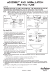
Fig.1
Motor
Black or Blue Wire
Switch Box
Wire Nut
Black
Washer
Center Plug
White Wire
White Wire
Hex Nut
Screw
Switch Box Cover
Nipple(-a)
Fixture
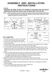
Fig.2
Motor
Screw
Black or Blue Wire
Wire Nut
Black Wire
Hex Nut
Washer
Switch Box
White Wire
Terminal (Groove)
Terminal ( Tongue)
White Wire
Switch Box Cover
Nipple(-a)
Plug
Cap
Set Screw
(6 x 32 20mmL)
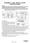
Fig.3
For Light Kit:
Motor
Socket
Nipple(-b)
1. Remove the switch box cover from the switch
Pull Chain
box of the fan by loosing the three screws.
Glass Shade
2. Unscrew the center plug from the switch box
cover and discard it.
Washer
3. For fan style that is shown in Fig.1: Attach the
Hex Nut
nipple(-a) of the light kit to the hole of the
Bottom Cap
Antler
switch box cover, then thread the wires
Finial
through the washer and hex nut, then secure
them tightly.
4. For fan style that is shown in Fig.2: Thread the fixture wire through the switch box cover,
the washer and hex nut. Then attach the cap to the switch box cover, then secure it with
two set screws (6x32 20mmL).
5. Pull out the wires from the switch box. Make wire connections using the wire nuts:
---The black wire from light kit to the black or blue wire from the fan.
---The white wire from light kit to the white wire from the fan.
---Carefully tuck wires back into the switch box.
6. Restore the switch box cover back to the switch box using the three screws.
7. Thread the pull chain through the glass shade, washer and hex nut, then attach the glass
shade to the socket by inserting nipple(-b) and secure it with the washer and hex nut.
Thread the pull chain through the antler and finial, then attach the antler to the glass shade
by inerting nipple(-b) and secure it with the finial. (See Fig.3)
8. Install bulbs (not included). See relamping label at socket area or packaging for maximum
allowed wattage.
9. Turn on the power at the main fuse or circuit breaker box.
(You can control the lights with the pull chain.)
LK33012 --- Page 1
060217
TM
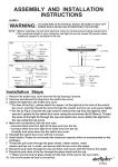
For Ceiling Light: (See Fig.4 & Fig.5)
Fig.4
Nipple(-a)
Coupling
Washer
Cap
Nipple(-c)
Fixture
Mounting Parts for Ceiling Light
1. Take out the the hex nut, washer, two bolt nuts,
groudnig pad and canopy from the hardware
package for ceiling light.
Outlet Box
House Grounding Wire
2. Unscrew and remove the nipple(-a), coupling, washer
Wire Nut
and the cap from the nipple(-a).( See Fig.4)
Screw
3. Attach the canopy with the open side facing upward
Mounting Strap
to the fixture by inserting the nipple(-c), then secure
Lock Nut
it with a washer, grounding pad and hex nut.
Green Grounding Screw
Mounting Screw
4. Attach two screws to the mounting strap, then
Fixture
Grounding Wire
secure them with two lock nuts. Adjust the length
Hex Nut
of the screws if necessary.
Grounding Pad
Washer
5. Attach the mounting strap to the outlet box by using
Canopy
two mounting screws.
6. Pull out the outlet wires and the house grounding
Bolt Nut
wire from the outlet box. Make wire connections
Nipple(-c)
using the wire nuts:
Fixture
Fig.5
---The black wire from fixture to the black wire from
the outlet box.
---The white wire from fixture to the white wire from the outlet box.
---Attach the fixture grounding wire to the mounting strap with the green grounding screw. Then
connect it to the house grounding wire with a wire nut.
Carefully tuck the wires back into the outlet box.
7. Attach the canopy to the mounting strap by inserting two screws, then secure them with the bolt
nuts.
8. Follow steps 7~9 as for Light Kit.
TM
LK33012 --- Page 2
060217