1
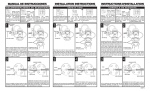
INSTALLATION INSTRUCTION WM-1
For Wall Mount Light Fixtures (Rev. 09/10/2007)
PREPARATION
CONNECTING THE WIRES
1.
Shut off power at the fuse box or circuit breaker box. If
necessary, remove old fixture and all mounting hardware from
wall junction box.
Connect the fixture wires to the junction box wires as shown in the wiring
Carefully unpack your new fixture and lay out all the parts on a
clear area. Take care not to lose any small parts necessary for
installation.
junction box, connect the Fixture Ground Wire to the Circular Strap or
2.
MOUNTING THE FIXTURE
3.
Your new fixture will be either a Circular Strap (Fig. A) mounting,
or a Crossbar (Fig. B) mounting type.
Determine which type your fixture is by the parts shipped with your
fixture and follow the appropriate instruction. NOTE: The wiring
is the same for either fixture.
diagram. Making sure all wire connectors are secured and do not easily
pull off with a slight tug. If there is no Green Ground wire from the
the Crossbar with the green Screw provided.
COMPLETING THE INSTALLATION
4.
Insert glass shade (F) all the way into holder (G) and lock it firmly
against the holder by threading socket ring (I) onto the screw shell
on the socket.
5.
Install the proper light bulbs for your fixture.
and test the fixture.
Fig. A CIRCULAR STRAP MOUNTING
Your installation is now complete.
A1. The Circular Strap (A) contains several pairs of threaded holes,
Find the pair of holes that match the hole spacing in your fixture
Canopy (D) and thread the two Studs (C) part way into the
Circular Strap (A). The side of Circular Strap marked “GND” must
face out
A2.
DO NOT EXCEED
THE SPECIFIED WATTAGE! Return the power to the junction box
Place the Circular Strap (A) over the junction box so the Studs
(C) are vertical or horizontal, as required by fixture type. Holding
the Strap in place, secure to the junction box by threading the
two junction box screws (B), through the slotted holes.
A3.
Connect the wires as described under “Connecting the Wires”.
A4.
Place the fixture Canopy (D) over the two Studs (C) so they
protrude through the holes in the Canopy (D). Thread the Cap
Nuts (E) onto the Studs (C) and continue turning until the Fixture
is snug against the wall. (See “Completing the Installation”)
Fig. A
G
F
I
Fig. B CROSSBAR MOUNTING
B1. Attach the Crossbar (A) to the junction box with the two Junction
box screws (B) as shown. The side of the Crossbar marked
“GND” must face out.
B2. Thread the Nipple (C) part way into the center hole of the
Crossbar.
B3. Connect the wires as described under “Connecting the Wires”.
Fig. B
C B
D
E
G
F
BA
C
I
FIXTURE
WIRES
Black or
Smooth
E
D
FIXTURE
WIRES
White or
Ribbed
HOUSE
WIRES
Black
(Hot)
FIXTURE
WIRES
Bare
Copper
(Ground)
HOUSE
WIRES
White
(Neutral)
In the event that you should have any installation
question or are missing parts, please contact
Customer Service. Customer service may be reached
weekdays a 1-800-527-0998 between the hours of
8:00am and 5:00pm PST (Pacific Standard Time).
LA-419E/S
A
JUNCTION
BOX
CROSSBAR
B4. Place the fixture Canopy (D) over the Nipple so the Nipple
protrudes through the center hole. Holding the fixture in place,
thread the Cap Nut (E) onto the end of the Nipple until fixture is
secure to the wall. (See “Completing the Installation”).
Note: Illustration (Fig. A and B) on this manual is
for installation purposes only. It may or may not be
identical to the fixture purchased.
JUNCTION
BOX
CIRCULAR STRAP
HOUSE
WIRES
Green
(Ground)
INSTRUCCIONES PARA LA INSTALACION WM-1
Para lamparas de pared (Rev. 09/10/2007)
PREPARACION
CONECTANDO LOS ALAMBRES
1.
Corte la corriente en la caja de fusibles o en el circuito principal.
Si fuera necesario, saque la lampara vieja y todo el montaje de
la caja de union de la pared.
2.
Desempaque cuidadosamente la nueva lampara y coloque todas
las partes en una superficie despejada. Tenga cuidado de no
perder las pardes pequenas que son necesarias para la
instalacion.
Conecte los alambres de la lampara a los alambres de la caja de union
como se muestra en el diagrama de eldctricidad. Asegurese que todas
las conecciones de los alambres esten firmes y que no se suelten con
un pequeno jalon. Si no hay alambre verde a tierra en la caja de union.
Conecte el alambre a tierra de la lampara a la abrazadera circular o a la
barra transversal con el tornillo verde que viente con el paquete.
MONTANDO LA LAMPARA
3.
TERMINANDO LA INSTALACION
4.
Su nueva lampara tendra un montaje de abrazadera circular
(Fig. A) o de barra transversal (Fig. B). Determine a que tipo
pertenece su lampara con las partes que vienen en el embalaje y
siga las instrucciones apropidas. NOTA: La instalacion electrica
se igual en ambas lamparas.
Meta la Panta de Vidrio (F) dentro el Socket (G) asegurelo con el
Anillo de la Cubierta (I) segido por el Rodillo.
5.
Instale el foco apropiado para su lampara NO SE EXCEDA EL
LOS WATTS EXPECIFICADO! Connecte la corriente electrica y pruebe
la lampara.
Su instalacion esta ahora completa.
Fig. A MONTAJE DE ABRAZADERA CIRCULAR
A1.
La abrazadera circular (A) contiene varios pares de agujeros
con rosca. Encuentre los agujeros quehacen pareja con el
agujero en la cubierta de su lampara (D) y atornille las dos
espigas (C), sin apretarias, en la abrazadera curcular (A). El lado
del travesano marcado “GND” debe de quedar hacia afuera
A2. Coloque la abrazadera circular (A) sobre la caja de union de tal
forma que las espigas (C) queden en posicion vertical o
horlzontal, dependiendo del tipo de lampara. Mientras sostiene
la abrazadera en su lugar. Asegurela a la caja de union
atronillando los dos tornillos de la caja de union (B) a traves de
las ranuras.
A3. Conecte los alambres en la forma en que describe en
CONECTANDO LOS ALAMBRES.
Fig. A
La Caja
de Union
Abrazadera Circular
G
F
A4. Coloquela cubierta de la lampara (D) sobre las dos espigas (C) de
tal forma que se asomen a traves de los agujeras de la cuierta
(D). Atronille las tuercas de tapa (E) a las espigas (C) y continue
atroniliando hasta que la lampara este firme contra la pared.
(Vea “COMPLETANDO LA INSTALACION”)
I
D
E
A
C B
Fig. B MONTAJE DE BARRA TRANSVERSAL
B1. Una la barra transversal (A) a la caja de union con los dos
tornillos de la caja de union (B) como se muestra con el dibujo.
El lado de la barra tranversal marcado “GND” debe de quedar
hacia afuera.
B2. Atonille la boquilla (C) sin apretar en el agujero central de la barra
transversal.
Fig. B
Barra Transversal
La Caja
de Union
G
F
B3. Conecte los alambres como se describe en “CONECTANDO LOS
ALAMBRES”
B4. Coloque la cubierta de la lampara (D) sobre la boquilla de tal
forma que la boquilla se asome a traves del agujero central.
Mientras sostiene la lampara en su lugar. Atronille los tornillos de
tapa (E) a la punta de la boquilla hasta que la lampara quede
firme contra la pared. (Vea COMPLETANDO LA INSTALACION).
C
I
D
ALAMBRES
DE LA
LAMPARA
VERDE O DE
COBRE
(A TIERRA)
ALAMBRES
DE LA
LAMPARA
BLANCO O
CON MARCA
ALAMBRES
DE LA
LAMPARA
NEGRO O
SIN MARCA
Nota: La ilustracion (Fig A and B) en este manual
esta para los propositos de la instalacion
solamente. Puede o puede no ser identical al
accesorio comprador.
E
ALAMBRES
DE LA
CASA
ALAMBRES
DE LA
CASA
BLANCO
(NEUTRAL)
En caso de preguntas sobre la instalacion o le faltaron
partes, porfavor hablar al departamento de Servicio
al Cliente al 1-800-527-0998 de Lunes a Viernes de
8:00 a.m. a 5:00 p.m. PST (Tiempo del Pacifico).
LA-419E/S
BA
ALAMBRES
DE LA
CASA