Transcript
INSTALLATION INSTRUCTIONS
For Model 71163-A144/143C (Rev. 04/30/2014)
READ AND SAVE THESE INSTRUCTIONS
W ARNING!
S H U T P O W E R O F F AT F U S E O R C I R C U I T B R E A K E R .
AVERTISSEMENT! COUPER LE COURANT AU NIVEAU DES FUSIBLES OU DU DISJONCTEUR.
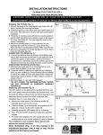
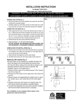
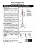
PREPARING FOR INSTALLATION (Fig. 1)
1. Shut off the power at the fuse box or circuit breaker. If
necessary, remove the old fixture, including the
mounting hardware.
2. Carefully unpack your new fixture, lay out all parts on a
clear area. Take care not to lose any small parts
necessary for installation.
3. Before installation, loosen the ball screws (H) to remove
glass holder (I).
4. Attach the circular strap (A) to the outlet box using the
mounting screws (B) (Size: #8-32N*L0.5”). The side of
the circular strap (A) marked “GND” must face out.
5. Thread the studs (C) into the pre-drilled holes of the
circular strap (A), spaced the same distance apart as the
holes in the back plate (D).
CONNECTING THE WIRES (Fig. 2)
6. At this point, connect the fixture wires to outlet box wires
as shown in Fig. 2, making sure that all wire connectors
are secured. If your outlet box has a ground wire (green
or bare copper), connect the fixture’s ground wire to it.
Otherwise, connect the fixture’s ground wire directly to
the circular strap (A) using the green screw provided.
After wires are connected, tuck them carefully inside the
outlet box.
COMPLETING THE INSTALLATION (Fig. 1)
7. Align back plate (D) onto studs (C) and secure with two
ball nuts (E).
8. To prevent moisture from entering the outlet box and
causing a shortage, use clear caulking (i.e.
Indoor/Outdoor silicone sealant) to outline the outside of
fixture back plate where it meets the wall leaving a space
at the bottom to allow moisture a means to escape
(Fig.3).
9. Install light bulb(s) (not included) in accordance with the
fixture’s specification. (DO NOT EXCEED THE
MAXIMUM WATTAGE RATING!) (NE PAS DEPASSER
LA PUISSANCE NOMINALE MAXIMALE!).
10. Align the glass shade (J) into glass holder (I) and
secure with screws (G).
11. Align the glass holder (I) with glass shade (J) over
socket (K) and into metal shade (F) and secure with ball
screws (H).
Fig.1
Set# A-020
- Circular Strap
- Ground Screw
- Mounting Screw*2
C
H
A
K
B
D
E
I
F
G
J
Fig.2
FIXTURE
WIRES
Black or
Smooth
FIXTURE
WIRES
White or
Ribbed
HOUSE
WIRES
Black
(Hot)
FIXTURE
WIRES
Bare
Copper
(Ground)
HOUSE
WIRES
White
(Neutral)
Fig. 3
Your installation is now complete. Return power to the
outlet box and test the fixture.
Note: Illustration (Fig. 1) on this manual is for
installation purposes only. It may or may not be
identical to the fixture purchased.
LA-2420E
CAULKING
BACKPLATE
HOUSE
WIRES
Green or
Bare
Copper
(Ground)