1
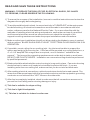
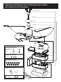
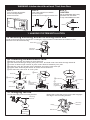
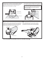
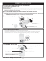
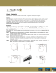
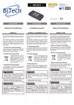
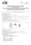
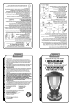
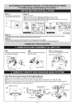
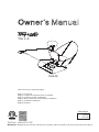
Owner’s Manual
The L.A.
3LA44
This instruction contains 6 pages:
Page 1: Foreword
Page 2: Unpack and inspect parts contained
Page 3: Hanging system installation
Page 4: Wire connection and Canopy installation
Page 4~5: Blade installation
Page 6: Remote
Net weight
6.0 KGS.
13.2 LBS.
3110124
Toll Free: 1-855-676-7247
WARNING : Read and follow these instructions carefully and be mindful of all warnings shown throughout.
READ AND SAVE THESE INSTRUCTIONS
WARNING : TO REDUCE THE RISK OF FIRE, ELECTRICAL SHOCK, OR INJURY
TO PERSONS, PLEASE OBSERVE THE FOLLOWING :
1]. To ensure the success of the installation, be sure to read the instructions and review the
diagrams thoroughly before beginning.
2]. To avoid possible electric shock, be sure electricity is TURNED OFF at the main power
box before wiring. All electrical connections must be made in accordance with local
codes, ordinances and/or the National Electric Code. If you are unfamiliar with the
methods of installing electrical wiring and products, secure the services of a qualified
and licensed electrician as well as someone who can check the strength of the
supportive ceiling members and make the proper installations and connections.
3]. Make sure that your installation site will not allow rotating fan blades to come in contact
with any object. BLADE SHOULD BE AT LEAST 7 FEET FROM FLOOR WHEN FAN IS IN
OPERATION.
4]. If possible, mount ceiling fan on a ceiling joist - the joist must be able to support the
motion and weight of the moving fan. If the fan will be mounted on a ceiling outlet box, a
4" x 2-1/8" deep METAL octagon box is required ; one UL listed as " suitable for fan
support ". The box and its supporting members must not be able to twist or work loose.
DO NOT USE PLASTIC BOXES. Installation on a concrete ceiling should be performed
by qualified personnel.
5]. Blades should be attached after motor housing is hung and in place. Fan motor housing
should be kept in carton until ready to be installed to protect its finish. If you are
installing more than one ceiling fan, make sure that you do not mix fan blade sets.
6]. After making electrical connections, spliced conductors should be turned upward. The
wires should be spread apart with the grounded conductor and the equipment-grounding
conductor on one side and the "HOT" wires on the other side.
7]. After fan is completely installed, check to make sure that all connections are secure to
prevent fan from falling and/or causing damage or injury.
8]. This fan is suitable for slope ceiling.
9]. This fan is light kit adaptable.
10]. This fan is suitable for indoor location use.
P1
Unpack and inspect fan carefully to be certain
all contents are included.
Mounting Bracket
Downrod
Canopy
Yoke cover
Wires
Blade
Fan Assembly
Hardware Bag
For Mounting Bracket:
Flat Washer x2
Spring Washer x2
Machine Screw x2
Wood Screw x2
For Wire Connection:
Wire Nut x 3
For Blade Installation:
Blade Screw x 13 (one spare screw included)
Remote *Battery Included
Hardware Bag
Wood Screw x2
P2
WARNING: blades should be at least 7 feet from floor
Note 1:
Note 2:
Turn off power at breaker
box to avoid possible
electrical shock.
Use metal outlet box suitable
for fan support.
Outlet box must support 35 lbs min.
Note 3:
CAUTION:
Do not fold blades with heavy
pressure from two sides.
It may cause blades to crack.
Blade
OFF OFF OFF
1. HANGING SYSTEM INSTALLATION
1A.Installing mounting bracket to ceiling outlet box
Install mounting bracket to outlet box in ceiling by using screws included with the outlet box and
washers from the hardware bag.
Outlet Box
Mounting
Bracket
1B. Installing Downrod and Yoke
1 Remove cross pin and cotter pin from downrod.
2 Insert downrod through canopy and yoke cover, and feed motor lead wires through downrod.
3 Loosen 2 downrod jam screws at yoke. Insert downrod assembly into yoke.
4 Insert the cross pin through yoke & downrod and secure with cotter pin.
5 Tighten both downrod jam screws to further secure downrod.
6 Pull down the yoke cover to cover yoke.
2 Wires
1 Cross Pin
1 Cotter Pin
Canopy
Downrod
Assembly
Downrod
4 Cotter Pin
3
5
Downrod Jam
Screw(2)
( Loosen ing)
Yoke
Yoke cover
Downrod Jam
Screw(2)
(Tightening)
Yoke cover
6
4 Cross Pin
Yoke
1C. Hanging the fan
Rotate fan so that the groove on the ball engages
the ridge in the mounting bracket.
Lift fan assembly onto mounting bracket.
Mounting
Bracket
Ridge
Ball Groove
Fan Assembly
P3
Mounting
Bracket
2. WIRE CONNECTION
Making electrical wire connection
Follow diagram below and make sure that all exposed wires are secured inside wire nuts or terminal block.
Note : Wires from house may vary in color and may not include ground wire ( green ).
*White wire from house to white wire from fan
*Black wire from house to black wire from fan
*Ground wire from house to green wire from downrod and from mounting bracket
*Secure with twist - lock wire nuts. (Included)
* After wiring is completed, gently push wires into junction box with wire nuts pointing upward.
Outlet Box
Wire Form House
From House
From Fan
White
White
Black
(AC-N)
(MOTOR-N)
(AC-L)
(MOTOR-L)
Green
( from downrod )
( for ground wire )
( from mounting bracket )
Black
Green
Green
3. CANOPY INSTALLATION
Note: Two screws are pre-installed on mounting bracket for canopy installation.
1 Push up canopy until two screws pre-screwed on mounting bracket are engaged with two key holes
on canopy.
2 Rotate canopy slightly until two pre-installed screw heads are engaged in the narrow end of key holes.
3 Tighten both screws.
1 Canopy
3 Screw (2)
2 Key Hole (2)
4. BLADES INSTALLATION
NOTE 1:
Please make sure blades are positioned with
"This side up" label facing the ceiling for step 4A.
(*Only clear blades have protection membrane.)
NOTE 2:
There may be two pieces of protection membrane on
two sides of blade for protecting blade from scratches.
Remove a part of the protection membrane on both
sides of blade end with "This side up" label for Step 4B.
Membrane
Th
is s
ide
up
This side up
P4
4A.
Blade end with "This side up" label should be attached
to the TOP side of fan motor (facing toward ceiling).
Make sure embossed spot on motor is properly
aligned with positioning hole on blade.
4B.
Once aligned, fasten the blade end onto TOP side
of fan motor with blade screws from hardware bag.
CAUTION: To avoid possible noise, do not fully
tighten the first blade screw while positioning.
Fasten both blade screws evenly after both
screws are in place.
Blade Screw
Embossed Spot
This side up
Positioning Hole
Th
is
sid
e
up
This side up
Blade
Membrane
Blade
Fan Assembly
4C.
If present, remove a part of the protection membrane
on both sides of the other blade end, and attach the
blade end onto DOWN side of fan motor with blade
screws and flat washers from hardware bag.
4D.
After repeating steps 4A to 4C twice until all
three blades are done, remove the protection
membrane from both sides of all three blades.
Blade
Membrane
Membrane
Turn on power at breaker box for remote setting.
P5
5:REMOTE INSTALLATION
5A. Initial Settings (Back side of Transmitter)
1. Code setting on TRANSMITTER.
1 Remove battery cover.
2 FAN code setting:
There are 4 switches for 16 possible code combinations just in case your house has other fans installed
with the same codes. You may change your code switches by using a small screwdriver or ball point pen
to slide each code switch firmly up or down.
Note: IF ONLY ONE FAN TO BE INSTALLED IN THE HOUSE, YOU CAN SKIP THIS STEP.
3 LIGHT On/Off-Dimming code setting :
This switch is to interchange light function while using incandescent bulbs (Dimming) or CFL bulbs (On/Off).
* Dimming function: Slide the code to “D” position (for incandescent bulbs)
* On/Off function: Slide the code to “ON” position (for CFL bulbs)
4 Install 12V 23AE battery x 1 pc.
2
ON
3
ECE D
D
ON
1 2 3 4 X
The picture is showing
for CFL bulbs.
1
4 12V 23AE Battery x 1 pc
5B. SETTING before starting fan.
Pressing the button “SET” for 3~5 seconds till the fan operates ,
which means this remote control is doing the setting. Fan will operate clockwise for 2.5 minutes
and anti-clockwise for 2.5 minutes, then stop automatically. (Totally 5 minutes for SETTING.)
SET
III
5C. TRANSMITTER BUTTON
IV
II
(Lowest Speed)
6 speeds from I (Lowest Speed)
to VI (Highest Speed).
V
I
VI
Reversing function
(Highest Speed)
Fan ON/OFF switch:
Light switch (two options)
1. On/Off (for CFL bulbs)
2. Dimming (for incandescent bulbs)
Your fan is ready for operation.
P6