Transcript
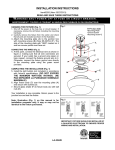
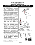
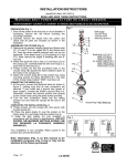
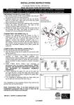
INSTALLATION INSTRUCTIONS
For item#2259 (Rev. 05/27/2013)
READ AND SAVE THESE INSTRUCTIONS
W ARNING!
S H U T P O W E R O F F AT F U S E O R C I R C U I T B R E A K E R .
AVERTISSEMENT! COUPER LE COURANT AU NIVEAU DES FUSIBLES OU DU DISJONCTEUR.
PREPARATION (Fig. 1)
1. Shut off the power at the fuse box or circuit breaker. If
necessary, remove the old fixture, including the
mounting hardware.
2. Carefully remove the fixture from the carton and check
that all parts are included as shown in the illustration.
INSTALLATION (Fig. 1)
3. Thread the two mounting studs (B) into the pre-drilled
holes in crossbar (A) (You can adjust to length of the
mounting studs if necessary).
4. Attach the crossbar (A) to the outlet box with mounting
screws (C) (size: #8-32N*L0.5”). The side of crossbar
(A) marked ”GND” must face out.
Fig.1
Set# A-016
-Crossbar
-Ground screw
-Mounting Screw*2
A
B
C
D
CONNECTING THE WIRES (Fig. 2)
5. At this point, connect the electrical wire as shown in
figure 2, making sure that all wire connectors are
secured. If your outlet has a ground wire (green or bare
copper), connect the fixtures ground wire to it.
Otherwise, connect the fixture ground wire directly to the
crossbar using the green screw provided.
COMPLETING THE INSTALLATION (Fig. 1)
6. Attach fixture body (D) to mounting stud (B) and secure
it with cap nuts (E).
7. Install the light bulb(s) (not included) in accordance with
fixture’s specifications.(DO NOT EXCEED THE
MAXIMUM WATTAGE RATING!)(NE PAS DEPASSER
LA PUISSANCE NOMINALE MAXIMALE!)
8. Secure glass shade (G) to fixture body (D) with ball nuts
(F).
Your installation is now complete. Return power to the
junction box and test the fixture.
Note: Illustration (Fig. 1) on this manual is for installation
purposes only. It may or may not be identical to the
fixture purchased.
LA-2343E
E
F
G