1
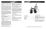
10. Attach the Handle Coupler to the end of the Pull Handle and join to the end of the Yoke by
aligning holes and then inserting M6 x 60 Pull Handle Bolt into first the Yoke, the coupler, then out
the other side of the Yoke. Secure with Washer and Lock Nut. See Figure 9.
3. Attach the Steering Link Connector (Part 12) to the Front Axle Support (Part 9) by
threading tw0 M8 x 15 Bolts (Part 23) through the top of the Link Connector (Part 12)
and into the Axle Support (Part 9). Secure at the bottom with Washer (Part 19) and the
Lock Nut (Part 20). See Figure 3
Link Connector
M8 x 15 Bolt
Handle Coupler
Yoke
Front Axle Support
Pull Handle/Towbar
M6 x 60 Bolt, Washer & Lock Nut
Washer & Lock Nut
Figure 3
4. Join the Yoke and the Center Front Axle Brace to the Front Axle Support by first threading one
M8 x 25 Bolt through the hole in the Center Front Axle Brace, then into the second hole in the
yoke and through the hole in the bottom of the Front Axle Support. From the bottom, insert
Washer and secure with a Lock Nut. See Figure 4A & 4B
Figure 9
11. Join the Back panel to the bed by inserting Large Quick Release Pin through the side loop located at the bottom of the Back Panel and the top edge of the Bed. See Figure 10
Center Front Axle Brace
Tabs facing out
M8 x 25 Bolt
Back Panel
M8 x 15 Bolt
Yoke
Bed
Quick release Pin
Figure 4A
Figure 4B
Figure 10
12. Repeat the process with Side Panels and the Front Panel to the Cart Bed. Lift Lock Handles that
have been pre-attached to the Front and Back Panels up to secure the Back, Front and the Side
Panels together by firmly pressing the lock Handle down and around the hook on the end of the
Side Panel.
8
5. Secure the Yoke to the Steering Link Connector by threading one M8 x 15 Bolt through the
first hole in the Yoke then into the Link Connector. Secure with Washer and Lock Nut. See Figure
4B.
5