1
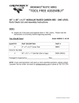
Modular Rustic Garden Wedge
(34”W x 48”L x 32”H - 18D) Assembly Instruction
1
Parts Identification
MRGW 34-48
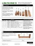
Stack matching pieces in piles. Using the parts list, locate and count
the individual pieces and verify that you have received the correct
number of pieces.
1
2
3
4
7
5
8
6
If any pieces are missing or replacement parts are required, contact
Gronomics at 1-855-299-6727.
NOTE: It is recommended to place a protective layer between
the ground and the pieces during assembly. This will help prevent
damage to the pieces.
10
Parts List
DESCRIPTION
ITEM
QTY.
1
4
CP41
Corner Post, 3-1/4” x 3-1/4” x 41-1/4”
2
8
R4501
Front & Back Side Rails, 45” x 5-5/8 x 13/16”
3
2
ES2613L
End Side Rails, 26-3/8” x 5-1/2” x 13/16”
4
2
ES2013
End Side Rails, 20-1/4” x 5-1/2” x 13/16”
5
2
ES1313
End Side Rails, 13.7/8” x 4-3/8” x 13/16”
6
2
ES0713
End Side Rails, 7-3/4” x 5-1/2” x 13/16”
7
2
SH43
8
1
BCR43
Bottom Center Rail, 43-3/8” x 2-1/2” x 13/16”
9
4
R3100
Post Cap, 4-5/8” x 4-5/8” x 1-1/2”
10
1
FL3652
Fabric Liner, 36” x 52”
2
PART #
9
Shelves, 43-3/4” x 5-1/2” x 1-3/8”
Post Assembly
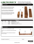
Place two 3-1/4” x 3-1/4” x 41-1/4” corner posts (Item 1)
together as shown.
1
Repeat procedure for the two remaining corner posts.
Packaged & Inspected by:
Date:
Continued
www.gronomics.com
East Bethel, MN USA
763-753-7374
3
5
Side Rail Assembly
Install the eight 45” x 5-5/8” side rails (Item 2) into the upper
part of the slots between the corner posts and slide down.
Bottom Center Rail Assembly
Install the 43-3/8” x 2-1/2” bottom center rail (Item 8) with the
tapered edges of the rail facing down.
Install the fabric liner into the Garden Wedge.
2
Soil Capacity: 6.5 Cubic Feet
2
8
6
4
Shelve Assembly
Install the two 43-3/4” x 5-1/2” shelves (Item 7) onto the side
rails on both sides of the Garden Wedge.
End Side Rail Assembly Continued
Install the four end side rails (Item 6, 5, 4 & 3) into the
upper part of the slots between the two corner posts and
slide down.
7
Repeat procedure on the opposite end with the four
remaining end side rails.
7
3
4
5
Post Cap Assembly
Remove the rubber cap from the post studs.
Align the hole of the 4” x 4” post cap (Item 9) with stud and
tighten until the post cap makes contact with the post. Do
not overtighten.
6
9
Stud
www.gronomics.com
East Bethel, MN USA
763-753-7374