1
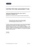
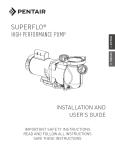
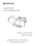
SEA FLOW® Pump Owner's Manual IMPORTANT SAFETY INSTRUCTIONS READ AND FOLLOW ALL INSTRUCTIONS SAVE THESE INSTRUCTIONS Table of Contents IMPORTANT PUMP WARNING AND SAFETY INSTRUCTIONS ............................................................................ I-II SECTION I. GENERAL INFORMATION .............................................................................................................. 1 SECTION II. MAINTENANCE .............................................................................................................................. 2 SECTION III. SERVICE ........................................................................................................................................ 3 SECTION IV. RESTART INSTRUCTIONS ............................................................................................................. 6 SECTION V. TROUBLESHOOTING ..................................................................................................................... 6 SECTION VI. TECHNICAL DATA .......................................................................................................................... 7 A. REPLACEMENT PARTS ............................................................................................................................ 7 B. PUMP CURVES .......................................................................................................................................... 8 WARNING Before installing this product, read and follow all warning notices and instructions accompanying this pump. Failure to follow safety warnings and instructions can result in severe injury, death, or property damage. Important Notice Attention Installer. This manual contains important information about the installation, operation and safe use of this product. This information should be given to the owner/operator of this equipment. WARNING RISK OF ELECTRICAL SHOCK OR ELECTROCUTION This pool pump must be installed by a licensed or certified electrician or a qualified pool installer in accordance with the 2008 National Electrical Code (“NEC”) to current and/or all applicable local codes and ordinances. The specific section of NEC covering your pump may vary depending on your location. Some states, and/or municipalities may not have adopted the current NEC code. In this case your state or local code may only be applicable and/or an earlier edition of the NEC may apply. Please check your local and state codes and regulations before commencing any installation of this pump. Improper installation could create, among other things, an electrical hazard which may result in death or serious injury to pool users, installers, or others due to electrical shock, and/or property damage. Always disconnect power to the pool pump at the circuit breaker before servicing the pump. Failure to do so could result in death or serious injury to pool users, installers or others (due to electrical shock) and/or property damage. P/N 350522 Rev. E 7/12 IMPORTANT PUMP WARNING AND SAFETY INSTRUCTIONS General Warnings • Never open the inside of the drive motor enclosure. There is a capacitor bank that holds a 230 VAC charge even when there is no power to the unit. • The pump is not submersible. • The pump is capable of high flow rates; use caution when installing and programming to limit pumps performance potential with old or questionable equipment. • Code requirements for the electrical connection differ from state to state. Install equipment in accordance with the National Electrical Code and all applicable local codes and ordinances. • Before servicing the pump; switch OFF power to the pump by disconnecting the main circuit to the pump. • This appliance is not intended for use by persons (including children) of reduced physical, sensory or mental capabilities, or lack of experience and knowledge, unless they have been given supervision or instruction concerning the use of the appliance by a person responsible for their safety. IMPORTANT NOTICE This guide provides installation and operation instructions for the SeaFlo ® Pump. Consult Lifegard Aquatics for questions regarding this equipment. Attention Installer: This guide contains important information about the installation, operation and safe use of this product.This information should be given to the owner and/or operator of this equipment after installation or left on or near the pump. Attention User: This manual contains important information that will help you in operating and maintaining this product. Please retain it for future reference. READ AND FOLLOW ALL INSTRUCTIONS SAVE THESE INSTRUCTIONS This is the safety alert symbol. When you see this symbol on your system or in this manual, look for one of the following signal words and be alert to the potential for personal injury. Warns about hazards that can cause death, serious personal injury, or major property damage if ignored. Warns about hazards that may cause death, serious personal injury, or major property damage if ignored. Warns about hazards that may or can cause minor personal injury or property damage if ignored. FAILURE TO FOLLOW ALL INSTRUCTIONS AND WARNINGS CAN RESULT IN SERIOUS BODILY INJURY OR DEATH. THIS PUMP SHOULD BE INSTALLED AND SERVICED ONLY BY A QUALIFIED POOL SERVICE PROFESSIONAL. INSTALLERS, POOL OPERATORS AND OWNERS MUST READ THESE WARNINGS AND ALL INSTRUCTIONS IN THE OWNER’S MANUAL BEFORE USING THIS PUMP. THESE WARNINGS AND THE OWNER’S MANUAL MUST BE LEFT WITH THE POOL OWNER. SUCTION ENTRAPMENT HAZARD: STAY OFF THE MAIN DRAIN AND AWAY FROM ALL SUCTION OUTLETS! NOTE indicates special instructions not related to hazards. F Carefully read and follow all safety instructions in this manual and on equipment. Keep safety labels in good condition; replace if missing or damaged. THIS PUMP PRODUCES HIGH LEVELS OF SUCTION AND CREATES A STRONG VACUUM AT THE MAIN DRAIN AT THE BOTTOM OF THE BODY OF WATER. THIS SUCTION IS SO STRONG THAT IT CAN TRAP ADULTS OR CHILDREN UNDER WATER IF THEY COME IN CLOSE PROXIMITY TO A DRAIN OR A LOOSE OR BROKEN DRAIN COVER OR GRATE. THE USE OF UNAPPROVED COVERS OR ALLOWING USE OF THE POOL OR SPA WHEN COVERS ARE MISSING, CRACKED OR BROKEN CAN RESULT IN BODY OR LIMB ENTRAPMENT, HAIR ENTANGLEMENT, BODY ENTRAPMENT, EVISCERATION AND/OR DEATH. The suction at a drain or outlet can cause: Limb Entrapment: When a limb is sucked or inserted into an opening resulting in a mechanical bind or swelling. This hazard is present when a drain cover is missing, broken, loose, cracked or not properly secured. Hair Entanglement: When the hair tangles or knots in the drain cover, trapping the swimmer underwater. This hazard is present when the flow rating of the cover is too small for the pump or pumps. Body Entrapment: When a portion of the body is held against the drain cover trapping the swimmer underwater. This hazard is present when the drain cover is missing, broken or the cover flow rating is not high enough for the pump or pumps. Evisceration/Disembowelment: When a person sits on an open pool (particularly a child wading pool) or spa outlet and suction is applied directly to the intestines, causing severe intestinal damage. This hazard is present when the drain cover is missing, loose, cracked, or not properly secured. When installing and using this electrical equipment, basic safety precautions should always be followed, include the following: Do not permit children to use this product. RISK OF ELECTRICAL SHOCK. Connect only to a branch circuit protected by a ground-fault circuitinterrupter (GFCI). Contact a qualified electrician if you cannot verify that the circuit is protected by a GFCI. This unit must be connected only to a supply circuit that is protected by a ground-fault circuit-interrupter (GFCI). Such a GFCI should be provided by the installer and should be tested on a routine basis. To test the GFCI, push the test button. The GFCI should interrupt power. Push the reset button. Power should be restored. If the GFCI fails to operate in this manner, the GFCI is defective. If the GFCI interrupts power to the pump without the test button being pushed, a ground current is flowing, indicating the possibility of an electric shock. Do not use this pump. Disconnect the pump and have the problem corrected by a qualified service representative before using. This pump is for use with permanent swimming pools and may also be used with hot tubs and spas if so marked. Do not use with storable pools. A permanently-installed pool is constructed in or on the ground or in a building such that it cannot be readily disassembled for storage. A storable pool is constructed so that it is capable of being readily disassembled for storage and reassembled to its original integrity. i IMPORTANT SAFETY INSTRUCTIONS For Installation of Electrical Controls at Equipment Pad (ON/OFF Switches, Timers and Automation Load Center) Install all electrical controls at equipment pad, such as on/off switches, timers, and control systems, etc. to allow the operation (startup, shut-down, or servicing) of any pump or filter so the user does not place any portion of his/her body over or near the pump strainer lid, filter lid or valve closures. This installation should allow the user enough space to stand clear of the filter and pump during system start-up, shut down or servicing of the system filter. IMPORTANT PUMP WARNING AND SAFETY INSTRUCTIONS Mechanical Entrapment: When jewelry, swimsuit, hair decorations, finger, toe or knuckle is caught in an opening of an outlet or drain cover . This hazard is present when the drain cover is missing, broken, loose, cracked, or not properly secured. NOTE: ALL SUCTION PLUMBING MUST BE INSTALLED IN ACCORDANCE WITH THE LATEST NATIONAL AND LOCAL CODES, STANDARDS AND GUIDELINES. TO MINIMIZE THE RISK OF INJURY DUE TO SUCTION ENTRAPMENT HAZARD: • A properly installed and secured ANSI/ASME A112.19.8 approved anti-entrapment suction cover must be used for each drain. • Each suction cover must be installed at least three (3’) feet apart, as measured from the nearest point to nearest point. • Regularly inspect all covers for cracks, damage and advanced weathering. • If a cover becomes loose, cracked, damaged, broken or is missing, replace with an appropriate certified cover. • Replace drain covers as necessary. Drain covers deteriorate over time due to exposure to sunlight and weather. • Avoid getting hair, limbs or body in close proximity to any suction cover, pool drain or outlet. • Disable suction outlets or reconfigure into return inlets. A clearly labeled emergency shut-off switch for the pump must be in an easily accessible, obvious place. Make sure users know where it is and how to use it in case of emergency. HAZARDOUS PRESSURE: STAND CLEAR OF PUMP AND FILTER DURING START UP Circulation systems operate under high pressure. When any part of the circulating system (i.e. locking ring, pump, filter, valves, etc.) is serviced, air can enter the system and become pressurized. Pressurized air can cause the pump housing cover filter lid and valves to violently separate which can result in severe personal injury or death. Filter tank lid and strainer cover must be properly secured to prevent violent separation. Stand clear of all circulation system equipment when turning on or starting up pump. Before servicing equipment, make note of the filter pressure. Be sure that all controls are set to ensure the system cannot inadvertently start during service. Turn off all power to the pump. IMPORTANT: Place filter manual air relief valve in the open position and wait for all pressure in the system to be relieved. Before starting the system, fully open the manual air relief valve and place all system valves in the “open” position to allow water to flow freely from the tank and back to the tank. Stand clear of all equipment and start the pump. IMPORTANT: Do not close filter manual air relief valve until all pressure has been discharged from the valve and a steady stream of water appears. Observe filter pressure gauge and be sure it is not higher than the pre-service condition. General Installation Information The Virginia Graeme Baker (VGB) Pool and Spa SafetyAct creates new requirements for owners and operators of commercial swimming pools and spas. Commercial pools or spas constructed on or after December 19, 2008, shall utilize: (A) A multiple main drain system without isolation capability with suction outlet covers that meet ASME/ANSI A112.19.8a Suction Fittings for Use in Swimming Pools, Wading Pools, Spas, and Hot Tubs and either: (i) A safety vacuum release system (SVRS) meeting ASME/ANSI A112.19.17 Manufactured Safety Vacuum Release systems (SVRS) for Residential and Commercial Swimming Pool, Spa, Hot Tub, and Wading Pool Suction Systems and/or ASTM F2387 Standard Specification for Manufactured Safety Vacuum Release Systems (SVRS) for Swimming pools, Spas and Hot Tubs or (ii) A properly designed and tested suction-limiting vent system or (iii) An automatic pump shut-off system. Commercial pools and spas constructed prior to December 19, 2008, with a single submerged suction outlet shall use a suction outlet cover that meets ASME/ANSI A112.19.8a and either: (A) A SVRS meeting ASME/ANSI A112.19.17 and/or ASTM F2387, or (B) A properly designed and tested suction-limiting vent system, or Pentair Water Pool and Spa IMPORTANT SAFETY INSTRUCTIONS (C) An automatic pumpatshut-off or For Installation of Electrical Controls Equipmentsystem, Pad (ON/OFF Switches, Timers and Automation Load Center) (D) Disabled submerged outlets, or (E) Suction outlets shall be reconfigured into return inlets. • All work must be performed by a qualified service professional, and must conform to all national, state, and local codes. • Install to provide drainage of compartment for electrical components. • These instructions contain information for a variety of pump models and therefore some instructions may not apply to a specific model. All models are intended for use in swimming pool applications. The pump will function correctly only if it is properly sized to the specific application and properly installed. Pumps improperly sized or installed or used in applications other than for which the pump was intended can result in severe personal injury or death. These risks may include but not be limited to electric shock, fire, flooding, suction entrapment or severe injury or property damage caused by a structural failure of the pump or other system component. The pump can produce high levels of suction within the suction side of the plumbing system. These high levels of suction can pose a risk if a person comes within the close proximity of the suction openings. A person can be seriously injured by this high level of vacuum or may become trapped and drown. It is absolutely critical that the suction plumbing be installed in accordance with the latest national and local codes for swimming pools. ® Warnings and safety instructions for Lifegard Aquatics pumps and other related products are available at: http://www.lifegardaquactics.com/literature or call (562) 404-4129 for additional free copies of these instructions. Install all electrical controls at equipment pad, such as on/off switches, timers, and control of systems, etc. to allow the For Installation Electrical Controls at Equipment Pad (ON/OFF operation (startup, shut-down, or servicing) of any pump or Switches, Timers Automation filter so the user does not place and any portion of his/her body Load Center) over or near the pump strainer lid, filter lid or valve closures. Install allspace electrical This installation should allow the user enough to stand controls at equipment pad, such as clear of the filter and pump during system start-up, shut down on/off switches, timers, and control systems, etc. to or servicing of the system filter. allow the operation (startup, shut-down, or servicing) of any pump or filter so the user does not place any portion of his/her body over or near the pump strainer lid, filter lid or valve closures. This installation should allow the user enough space to stand clear of the filter and pump during system start-up, shut down or servicing of the system filter. Please refer to http://www.lifegardaquactics.com for warning and safety instructions related to this product. SAVE THESE INSTRUCTIONS ii WARNING To reduce the risk of injury, do not permit children to use this product unless they are closely supervised at all times. CAUTION This pump is for use with permanently installed pools and may also be used with hot tubs and spas if so marked. Do not use with storable pools. A permanently installed pool is constructed in or on the ground or in a building such that it cannot be readily disassembled for storage. A storable pool is constructed so that it may be readily disassembled for storage and reassembled to its original integrity and has a maximum dimension of 18 feet (5.49m) and a maximum wall height of 42 inches (1.07m). CAUTION For hot tubs and spa pumps, do not install within an outer enclosure or beneath the skirt of a hot tub or spa unless so marked. SECTION I. GENERAL INFORMATION A. Wiring. WARNING RISK OF ELECTRICAL SHOCK OR ELECTROCUTION This pool pump must be installed by a licensed or certified electrician or a qualified pool installer in accordance with the 2008 National Electrical Code (“NEC”) and/or all applicable local codes and ordinances. The specific section of NEC covering your pump may vary depending on your location. Some states, and/or municipalities may not have adopted the current NEC code. In this case your state or local code may only be applicable and/or an earlier edition of the NEC may apply. Please check your local and state codes and regulations before commencing any installation of this pump. Improper installation could create, among other things, an electrical hazard which may result in death or serious injury to pool users, installers, or others due to electrical shock, and/or property damage. Always disconnect power to the pump at the circuit breaker before servicing the pump. Failure to do so could result in death or serious injury to service people, users or others due to electric shock. Read all servicing instructions before working on the pump. SUPPLY WIRE SIZES (AWG) 1. Be sure all electrical breakers and switches are turned (size and length by horsepower) off before wiring motor. hp 115 volts 230 volts 2. Be sure the supply line voltage matches the motor voltage 50 ft. 100 ft. 150 ft. 50 ft. 100 ft. 150 ft. listed on the motor plate (example 230 VAC or 115 1/3 14 14 12 14 14 14 VAC). If they do not match, permanent motor damage may occur. 1/2 14 12 10 14 14 14 3. Use #12 AWG for wire runs upto 100 feet (30.5 meters) and 3/4 12 12 10 14 14 14 #10 AWG for lengths longer than 100 feet (30.5 meters). 1 12 10 8 14 14 14 When in doubt use a heavier gauge (larger diameter) wire. For 1½ 10 10 8 14 14 12 more information , see CHART 1. 2 10 8 8 14 12 12 4. Use strain relief and be sure all electrical connections are clean 3 12 12 10 and tight. Chart 1. 5. Cut wires to the appropriate length so they don’t overlap or touch when connected to the terminal board. 6. Permanently ground the motor using the green ground terminal located on the inside of the motor canopy or access plate, see Figure 1. Use the correct wire size and type specified by National Electrical Code. Make sure the ground wire is connected to an electrical service ground. 1 NOTE When pump is mounted permanently within 5 ft. of the inside walls of a swimming pool, you must use a No. 8 AWG or larger conductor to connect to bonding conductor lug. Typical Ground Screw Terminal 7. Bond the motor to the pool structure in accordance with the National Typical Wiring Electrical Code. Use a solid No. 8 AWG or larger copper conductor. Terminals Run a wire from the external bonding to the pool bonding structure, see Figure 1. NPT 1/2” for Cord Strain Relief 8. Connect the wire from the accessible bonding lug on the motor to all Typical metal parts of the swimming pool, spa, or hot tub structure and to all Bonding Lug electrical equipment, metal conduit, and metal piping within 5 feet of Field Wiring Compartment the inside walls of the swimming pool, spa, or hot tub. For Figure 1. Canada, a 6 AWG or larger solid copper bonding conductor is required. 9. The pump should be permanently connected to either a circuit breaker, 2-pole timer or 2-pole relay. If AC power is supplied by a GFCI circuit breaker, use a dedicated circuit breaker that has no other electrical loads. Note: When the pump is started and stopped by removing power with a relay or timer, a two-pole device should be used to apply and remove power to both POWER LINE TERMINALS. B. The Pump Strainer Basket. This unit, sometimes referred to as the ‘Hair and Lint Pot’, is the unit in front of the volute. Inside the chamber is the basket which must be kept clean of leaves and debris at all times. View basket through the ‘See Through Lid’ to inspect for leaves and debris. Regardless of the length of time between filter cleaning, it is most important to visually inspect the hair and lint pot basket at least once a week. A dirty basket will reduce the efficiency of the filter and heater and also put an abnormal stress on the pump motor which would result in a costly repair bill. SECTION II. MAINTENANCE WARNING Clamp, pot DO NOT open the strainer pot if pump fails to prime or if pump has been operating without water in the strainer pot. Pumps operated in these circumstances may experience a build up of vapor pressure and may contain scalding hot water. Opening the pump may cause serious personal injury. In order to avoid the possibility of personal injury, make sure the suction and discharge valves are open and strainer pot temperature is cool to touch, then open with extreme caution. Lid O-ring, lid CAUTION Basket To prevent damage to the pump and filter and for proper operation of the system, clean pump strainer and skimmer baskets regularly. A. Pump Strainer Basket Cleaning Procedures. 1. Turn off motor. 2. Relieve pressure in the system by allowing the water to cool. 3. Gently tap the clamp in a counter-clockwise direction to remove the clamp and lid. 2 Pot Fig- 4. 5. 6. 7. Put the debris from the basket into the trash and rinse out the basket. If the basket is cracked, it should be replaced. Replace the basket and fill the pump pot and volute up to the inlet port with water. Clean the cover, cover O-ring, and sealing surface of the pump pot. Grease the O-ring with silicone. Reinstall the lid by placing the clamp and the lid on the pot; see Figure 2. a. Make sure the lid O-ring is properly placed. Seat the clamp and lid then turn clockwise until the handles are perpendicular to the inlet/outlet ports; see Figure 3. 8. Turn the power “ON” at the house circuit breaker. Reset the pool time clock to the correct time. WARNING THIS PUMPS OPERATES UNDER HIGH PRESSURE. WHEN ANY PART OF THE CIRCULATING SYSTEM (e.g., LOCK RING, PUMP, FILTER, VALVES, ETC.) IS SERVICED, AIR CAN ENTER THE SYSTEM AND BECOME PRESSURIZED. PRESSURIZED AIR CAN CAUSE THE LID TO SEPARATE WHICH CAN RESULT IN SEVERE INJURY, DEATH, OR PROPERTY DAMAGE. TO AVOID THIS POTENTIAL HAZARD, FOLLOW THESE INSTRUCTIONS. Clamp 9. Open the High Flow manual air relief valve on top of the filter. Figure 3. Lid 10. Stand clear of the filter. Start the pump. 11. Bleed air from the filter until a steady stream of water comes out. Close the High Flow manual air relief valve. B. Winterizing. 1. If the air temperature drops below 35° F., the water in the pump can Volute freeze and cause damage. Freeze damage is not warrantable. 2. To prevent freeze damage follow the procedures listed below: a. Shut off electrical power for the pump at the house circuit breaker. b. Drain the water out of the pump case by removing the two thumb-twist drain plugs from the case. Store the plugs in the pump basket. c. Cover the motor to protect it from severe rain, snow and ice. d. Do not wrap the motor in plastic. It will cause condensation and rust on the inside of the motor. C. Care of Electric Motor. 1. Protect from heat. a. Shade the motor from the sun. b. Any enclosure must be well ventilated to prevent overheating. c. Provide ample cross ventilation. 2. Protect against dirt. a. Protect from any foreign matter or splashing water. b. Do not store (or spill) pool chemicals near the motor. c. Avoid sweeping or stirring up dust near the motor while it is operating. d. If a motor has been damaged by dirt it voids the motor warranty. 3. Protect against moisture. a. Protect from splashing pool water. b. Protect from the weather. c. Protect from lawn sprinklers. 3 d. If a motor has become wet - let it dry before operating. Do not allow the pump to operate if it has been flooded. e. If a motor has been damaged by water it voids the motor warranty. NOTE DO NOT wrap motor with plastic or other air tight materials. The motor may be covered during a storm, for winter storage, etc., but never when operating, or expecting operation. NOTE When replacing the motor, be certain that the motor support is correctly positioned to support the size of motor being installed. SECTION III. SERVICE WARNING RISK OF ELECTRICAL SHOCK OR ELECTROCUTION This pool pump must be installed by a licensed or certified electrician or a qualified pool installer in accordance with the 2008 National Electrical Code (“NEC”) and/or all applicable local codes and ordinances. The specific section of NEC covering your pump may vary depending on your location. Some states, and/or municipalities may not have adopted the current NEC code. In this case your state or local code may only be applicable and/or an earlier edition of the NEC may apply. Please check your local and state codes and regulations before commencing any installation of this pump. Improper installation could create, among other things, an electrical hazard which may result in death or serious injury to pool users, installers, or others due to electrical shock, and/or property damage. Always disconnect power to the pool pump at the circuit breaker before servicing the pump. Failure to do so could result in death or serious injury to pool users, installers or others (due to electrical shock) and/or property damage. WARNING DO NOT open the strainer pot if pump fails to prime or if pump has been operating without water in the strainer pot. Pumps operated in these circumstances may experience a build up of vapor pressure and may contain scalding hot water. Opening the pump may cause serious personal injury. In order to avoid the possibility of personal injury, make sure the suction and discharge valves are open and strainer pot temperature is cool to touch, then open with extreme caution. A. Pump Disassembly. 1. All moving parts are located in the rear sub-assembly of this pump. Tools required: a. 3/32 inch Allen head wrench. b. 1/2 inch open end wrench. c. 9/16 inch open end wrench. d. Flat blade screwdriver. 2. To remove and repair the motor sub-assembly perform the following procedures. a. Turn off the pump circuit breaker at the main panel. b. Drain the pump by removing the drain plugs. c. Remove the 6 bolts that hold the main pump body (strainer pot/volute) to the rear sub-assembly. d. GENTLY pull the two pump halves apart, removing the rear sub-assembly. e. Use a 3/32 inch Allen head wrench to loosen the two holding screws located on the diffuser. 4 f. Hold the impeller securely in place and remove the impeller lock screw by using a #2 Phillips screwdriver. The screw is a left-handed thread and loosens in a clockwise direction. g. Remove the shaft cap located at the back of the motor and hold the shaft secure with a ½ inch open-end wrench. h. To unscrew the impeller from the shaft, twist the impeller counter-clockwise. i. Remove the four bolts from the seal plate to the motor, using a 9/16 inch wrench. j. If replacing the mechanical seal set, see Section B. Pump Reassembly/Seal Replacement on below. B. Pump Reassembly/Seal Replacement; see Figure 4. NOTE It is important that the O-rings be kept clean and well lubricated. We recommend a silicone base lubricant for best results. CAUTION Be sure not to scratch or mar the polished shaft seal faces; the seal will leak if faces are damaged. 1. When installing the replacement shaft seal, use silicone sealant on the metal portion before pressing into the seal plate, being careful to keep off of the seal face. Ensure the seal is fully seated and allow 24 hours for sealant to cure. (Complete seal plate w/seal replacement kit available, P/N 350201/350101.) 2. Before installing the ceramic section of the seal into the impeller, be sure the impeller is clean. Use a light density soap and water to seal the seal. Press the seal into the impeller with your thumbs and wipe off the ceramic and carbon faces with a clean cloth. Bolt 3. Remount the seal plate to the motor by installing bolts in an X pattern and tightening to 70 in-lbs. 4. Clean the motor shaft thread and the impeller insert, then screw the impeller onto the motor shaft. 5. Screw in the impeller lock screw (counter-clockwise and tighten to 25 in-lbs. while holding the motor shaft with wrench). 6. Remount the diffuser onto the seal plate. Make sure the plastic pins and holding screw inserts are aligned. 7. Grease the diffuser O-ring and seal plate gasket. Seal Plate Gasket Lockscrew Water Slinger Motor Shaft Impeller Lockscrew Seal Figure 4. 8. Grease the bolt threads, assemble the motor sub-assembly to the strainer pot-pump body by using the two through bolts for proper alignment. Do not tighten the through bolts until all 6 bolts are in place and finger tightened. Torque in a cross pattern to 110 in-lbs. 9. Fill the pump with water. 10. Reinstall the pump lid and plastic clamp; see SECTION IV. RESTART INSTRUCTIONS. 11. Reprime the system. C. The Shaft Seal. 1. The Shaft Seal consists primarily of two parts, a rotating member and a ceramic seal. 2. The pump requires little or no service other than reasonable care, however, a Shaft Seal may occasionally become damaged and must be replaced. 5 CAUTION The polished and lapped faces of the seal could be damaged if not handled with care. CAUTION In mild climate area, when temporary freezing conditions may occur, run your filtering equipment all night to prevent freezing. SECTION IV. RESTART INSTRUCTIONS A. If pump is installed below the water level of the pool, close return and suction lines prior to opening hair and lint pot on pump. Make sure to reopen valves before to operating. CAUTION DO NOT run the pump dry. If the pump is run dry, the mechanical seal will be damaged and the pump will start leaking. If this occurs, the damaged seal must be replaced. ALWAYS maintain proper water level in your pool (half way up skimmer opening). If the water level falls below the skimmer opening, the pump will draw air through the skimmer, losing the prime and causing the pump to run dry, resulting in a damaged seal. Continued operation in this matter could cause a loss of pressure, resulting in damage to the pump case, impeller, and seal and may cause property damage and personal injury. B. Priming the Pump. 1. The pump strainer pot must be filled with water before the pump is initially started. Follow these steps to prime the pump: a. Remove the pump lid plastic clamp. Remove the pump lid. b. Fill the pump strainer pot with water. c. Reassemble the pump cover and plastic clamp onto the strainer pot. The pump is now ready to prime. d. Open the air release valve on the filter, and stand clear of the filter. e. Turn on the switch or time clock. f. When water comes out of the air release valve, close the valve. The system should now be free of air and recirculating water to and from the pool. 2. For 2-speed pumps: a. Pump should run on high-speed for priming. b. The pump should not run longer than eight (8) minutes before priming is achieved. SECTION V. TROUBLESHOOTING A. Failure to Pump. 1. Pump will not prime - too much air. Remedy: a. Check suction piping and valve glands on any suction gate valves. b. Secure lid on pump strainer pot and make sure lid gasket is in place. c. Check water level to make sure skimmer is not drawing air. 2. Pump will not prime--not enough water. Remedy: a. Make sure suction lines, pump strainer, and pump volute are full of water. b.Make sure valve on suction line is working and open, (some systems do not have valves). c. Check water level to make sure water is available through skimmer. 3. Pump strainer clogged. Remedy: a. Clean pump strainer pot. 4. Pump strainer gasket defective. Remedy: a. Replace gasket. B. Reduced Capacity and/or Head. 1. Air pockets or leaks in suction line. Remedy: a. See item A.1. of this section, above. 2. Clogged impeller. Remedy: a. Disassemble; per SECTION III. A. Pump Disassembly. b. Clean debris from impeller. If debris cannot be removed, complete the following steps. (1) Remove left hand thread anti-spin bolt and O-ring. (2) Remove, clean and reinstall impeller. c.Reassemble; per SECTION III. B. Pump Reassembly. 3. Pump strainer clogged. - Remedy: a. Clean suction trap. 6 SECTION VI. TECHNICAL DATA A. Replacement parts. Item No. 1 357199 Clamp, Cam & Ramp, almond 1 357150 Clamp, Cam & Ramp, black 27 071313S 2 Cover, clear, WFE pump 3/4 HP, 60 Hz, WFE-2, 3 & 24, 1 spd., almond, 9 lbs. 357151 27 071314S 2 Cover, chemical resistant Cam & Ramp 1 HP, 60 Hz, WFE-4 & 26, 1 spd., almond, 33 lbs. 357156 27 071315S 3 O-ring, WFE cover 1-1/2 HP, 60 Hz, WFE-6 & 28, 1 spd., almond, 39 lbs. 350013 27 071316S 4 070387 Basket, AQ & WFE 2 HP, 60 Hz, WFE-8 & 30, 1 spd., almond, 40 lbs. 27 071317S 5 Bolt, 3/8, 16 x 1.25 hex hd. SS, 4 req. 3 HP, 60 Hz, WFE-12, 1 spd., almond, 40 lbs. 070430 27 356630S 6 Washer, 3/8 x 13/16 o.d. SS, 6 req. 1 HP, WFDS-4 & 26, 2 spd., 34 lbs. 072184 27 071320S 7 Bolt, 3/8, 16 x 1.75 hex hd. SS, 2 req. 1-1/2 HP, WFDS-6 & 28, 2 spd., 36 lbs. 070431 27 071321S 8 Nut, 3/8, 16 hex hd., 2 req. 2 HP, WFDS-8 & 30, 2 spd., 45 lbs. 071403 27 075232S 9 357100 Black Gasket for Seal Plate 1/2 HP, WF-2 & 23, 1 spd., almond, 39 lbs. 27 075233S 10 Volute, WFE pump & pot, almond 3/4 HP, WF-3 & 24, 1 spd., almond, 26 lbs. 350015 27 075234S 10 27 075235S 11 1-1/2 HP, WF-6 & 28, 1 spd., 39 lbs. 355227 Volute, WFE pump & pot, black O-ring parker No. 2-238, WFE pump 1 HP, WF-4 & 26, 1 spd., almond, 28 lbs. 357157 27 075236S 12 Set screw, 4-40 x 1-1/8 WFE, 2 req. 2 HP, WF-8 & 30, 1 spd., 32 lbs. 27 075237S 13 071660 072928 Diffuser assembly, WFE-12, 3 HP only 3 HP, WF-12, 1 spd., almond, 40 lbs. 27 355203S WFK-4 motor, 3 ph, 1 spd., black, 28 lbs. 13 072927 Diffuser assembly, WFE-2–8, 1/2 HP – 2.5 HP 27 355204S WFK-6 motor, 3 ph, 1 spd., black, 30 lbs. 14 071652 Set screw, 1/4, 20 x 1 lh. Phillips 27 355205S WFK-8 motor, 3 ph, 1 spd., black, 37 lbs. 15 075713 Rubber washer, WFE pump 27 355398S WFK-12 motor, 3 ph, 1 spd., black, 35 lbs. 16 071734S 27 356626S 1 HP, 3 ph, 1 spd., sq. flg., almond 16 27 356627S 1-1/2 HP, 3 ph, 1 spd., sq. flg., almond 17 071728 070429 Seal PA-7 w/ceramic seat, PS1000 Seal A7 w/ceramic seat, PS201 ➊ Bolt, 3/8, 16 x 7/8 SS hex hd., 4 req. 27 356628S 2 HP, 3 ph, 1 spd., sq. flg., almond 18 350201 27 356629S 3 HP, 3 ph, 1 spd., sq. flg., almond 27 356630S 1 HP, 1.5A, 2 spd., 1 ph, sq. flg., almond 18 350101 79129900 2-Speed Toggle Switch Seal Plate Kit: Seal plate (almond), Gasket (black), with installed Seal (Includes items: 9, 16, & 18) Seal Plate Kit: Seal plate (black), Gasket (black), with installed Seal (Includes items: 9, 16, & 18) Pot Assembly, Almond NPT. (Includes items: 1-4, 10, 24 [qty. 2], 25 [qty. 2]) Pot Assembly, Black NPT. (Includes items: 1-4, 10, 24 [qty. 2], 25 [qty. 2]) P/N Item No. Description Seal Plate Kit WFE, black (Includes Mechanical Seal installed) Foot, WFE-4 pump, almond 070927 19 357159 Foot, black 20 070929 Foot insert, WFE pump, almond 20 357160 Foot insert, WFE pump, black 21 071657 Screw, 1/4, 20 x 1 in. hh. SS, 2 req. 22 071406 Nut, 1/4, 20 hex. hd. SS, 2 req. 23 072183 Nut, 1/4, 20 hex. hd. SS, 2 req. 24 071131 Knob plug drain, 2 req. almond Description Motors Seal Plate Kit WFE, almond (Includes Mechanical Seal installed) 19 P/N Not Shown 350202 350203 357243 357244 Power End Subassy. Includes Items: 12-18, 27-28 ITEM 28 — IMPELLER CHART HP 1/2 3/4 1 1-1/2 2 3 PUMP MODEL WFE-2, WF-2, WF-23, WFK-2 WFE-3, WFE-24, WF-3, WF-24, WFK-3, WFDS-24 WFE-4, WFE-26, WF-4, WF-26, WFK-4, WFDS-4, WFDS-26 WFE-6, WFE-28, WF-6, WF-28, WFK-6, WFDS-6, WFDS-28 WFE-8, WFE-30, WF-8, WF-30, WFK-8, WFDS-8, WFDS-30 WFE-12, WF-12 STD PART NO. 073126 073127 075136 WFE-2 075137 WFE-3, WFE-24 075138 WFE-4, WFE-26 075139 WFE-6, WFE-28 075140 WFE-8, WFE-30 075141 WFE-12 075145 WFDS-3, WFDS-24 075142 WFDS-4, WFDS-26 075143 WFDS-6, WFDS-28 075144 WFDS-8, WFDS-30 075251 WF-2, WF-23 075252 WF-3, WF-24 075253 WF-4, WF-26 075254 WF-6,WF-28 075255 WF-8,WF-30 075256 WF-12 Fluid Ends-All Parts, w/o Motor 073128 073129 073130 075452 WFE-3 fluid end, 3/4 HP 075453 WFE-4 fluid end, 1 HP 075454 WFE-6 fluid end, 1-1/2 HP 075455 WFE-8 fluid end, 2 HP 075456 WFE-12 fluid end, 3 HP CSA/CUL (only) for Canada. Energy efficient, single phase. 073131 Standard efficiency, single phase. Two speed, single phase. 7 26 27 28 B. Pump Curves. SEA FLOW® SEA FLOW® Dual Speed Models Single Speed Models SAVE THESE INSTRUCTIONS 8 Warranty Policy • Warranty period starts from date of purchase and must be validated with copy of original purchase receipt. • Warranty requests by phone will not be honored. • Warranty items returned without copy of original purchase receipt will not be honored. • Products purchased from EBay, Craig’s List, etc. cannot be honored for warranty unless returned by original purchaser with proof of purchase. • All items must first be returned to Lifegard Aquatics for inspection, evaluation, and processing to determine if product qualifies for warranty replacement or repair. No warranty (repair, replacement, or credit) will be issued prior to inspection of product. • Please contact us first for warranty assistance. Many times the product can be repaired without the cost and time involved in sending it back. If absolutely necessary, return product FREIGHT PREPAID for warranty evaluation and processing. Call or email our office to obtain RMA number and shipping address. Lifegard Aquatics Tel (562)404-4129 Fax (562)404-4159 Email: [email protected] • 3 year warranty from date of purchase on Quiet One Pump Motors Only. • 60 day warranty from date of purchase on Shafts and Impellers for All Types of Pumps. • 60 day warranty from date of purchase on all Ultraviolet Bulbs. • 60 day warranty from date of purchase on all Test Strips. • 1 year warranty from date of purchase on All Other Products. © 2012 Lifegard Aquatics Inc. All rights reserved. Tel: (562) 404-4129 FAX (562) 404-4159 Email: [email protected] - visit www.lifegardaquatics.com Sea Flow® is a registered trademark of Lifegard Aquatics Inc. and/or its affiliated companies in the United States and/or other countries. *350522* P/N 350522 Rev. E 7/12