1
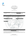
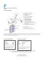
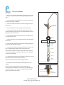
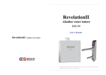
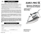
PRO-RO 6-Stage Reverse Osmosis System System tested and certified by NSF International against NSF/ANSI Standard 58 for the reduction of substances specified on the performance data sheet. Pelican Water Systems 877-842-1635, www.pelicanwater.com 1 Rev: 0814 Please fill out the following information at the time of installation. Save for future reference. Model: Pelican PRO-RO Date Code: Install Date: Sold by: Installed By: Service Center Phone Number: . Introduction to the PRO-RO Congratulations on your purchase of the PRO-RO six stage reverse osmosis system. The PRO-RO features a four-stage prefilter, membrane and postfilter housed in a single cartridge. The final two stages consist of a granular activated carbon polishing filter and a calcite remineralizing filter. When properly maintained, this system will provide you with years of trouble-free service. The next sections contain important information on the proper care and maintenance of your system, please take a few minutes to read through this information. The cartridges in this system must be replaced on a regular basis to maintain efficiency and to ensure high water quality. These cartridges work together and must be replaced every 6-12 months. Any significant change in performance of the system should be investigated promptly to avoid secondary damage or deterioration to other parts of the system. Normally, the reverse osmosis membrane is replaced during an annual filter change. However, if at any time you notice a reduction in water production or an unpleasant taste in the reverse osmosis water, it could be time to replace the membrane. Nimbus recommends replacing the membrane when TDS reduction falls below 75%. In order to ensure the system is functioning properly, a water sample must be sent in to Pelican every 6 months for a free diagnosis of your membrane performance. To send a water sample, use two clean containers and fill one with 1/2 cup of tap water and the other with 1/2 cup of RO water. Clearly label each sample. Send the samples to Pelican Water Systems, 3060 Performance Circle, Suite 2, Deland, FL 32724, Attn: “Water Sample Testing” along with your contact information. Pelican will test the samples and contact you with the results. CAUTION: Improperly installed systems could result in water damage due to leaks or flooding. Proper installation of this system requires familiarity with standard sink plumbing and proper use of common hand and power tools. If you are not familiar with standard sink plumbing and proper use of common hand and power tools or have any difficulty with the installation of this system, consult a licensed professional, such as a contractor or plumber. NOTE: This system has been designed for installation by licensed professionals, such as a contractor or plumber. Stage Description Replacement Interval Part Number 1-4 4-Stage Cartridge 1) 20 micron sediment prefilter 2) Granular activated carbon (GAC) prefilter 3) Reverse osmosis membrane 4) Granular activated carbon postfilter 18 months 104863 5-6 Granular activated carbon (GAC) and calcite (remineralization) postfilter 6-12 months 104851 Pelican Water Systems 877-842-1635, www.pelicanwater.com 3 Limited Warranty This Limited Warranty extends to the original purchaser of the system only. This warranty covers all Manufacturer-supplied items only that prove to be defective in material, workmanship or factory preparation. This warranty covers parts only; all labor is excluded from this warranty, including, but not limited to, services related to the removal, replacement, installation, adjustment, maintenance and/or repair of the unit or its components items. excludes all non-Manufacturer labor required for any servicing of the unit, including, but not limited to, servicing related to installation, adjustment, maintenance and repair of the unit. This warranty applies only for the first full calendar year from date of purchase. The following items are excluded from this warranty: membranes, filters, O-rings, and all other parts or components that require regular replacement as a result of ordinary usage. Disclaimers: This Limited Warranty applies only if the system is installed, used and maintained in compliance with all instructions and requirements enclosed with the system. This warranty will be void for failure to observe the following conditions: 1. 2. 3. 4. 5. 6. 7. 8. 9. The system is to be used with potable water from a municipal water system. Feed water pressure to the unit is no less than 40 PSI and no greater than 80 PSI. The system is to be used on water supplies with chlorine concentrations of 1.0 mg/L (ppm) or less. Feed water temperature to the unit must be no less than 40°F and no more than 100°F. Total dissolved solids in feed water must be less than 2,000 mg/L (ppm). Feed water must have a pH between 4 and 8. Turbidity must be less than 1.0 NTU. SDI must be less than 5. Feed water must be completely free of iron, manganese or hydrogen sulfide. Do not use with water that is microbiologically unsafe or of unknown quality without adequate disinfection before or after the system. The Manufacturer does not know the characteristics of your water supply. The quality of water supplies may vary seasonably or over a period of time. Your water usage may vary as well. Water characteristics can also change if the drinking water appliance is moved to a new location. The Manufacturer assumes no liability for the determination of the proper equipment necessary to meet your requirements, and we do not authorize others to assume such obligation on our behalf. This Limited Warranty does not cover any Manufacturer-supplied items that are defective as a result of the use of improper parts, equipment or materials. This warranty does not cover alterations or modifications of the unit, or failure of a unit caused by such alterations and modifications This Limited Warranty does not cover malfunctions of the unit due to tampering, misuse, alteration, lack of regular maintenance, misapplication, fouling due to hydrogen sulfide, manganese or iron, scaling from excessive hardness, turbidity greater than 1.0 NTU, Silt Density Index (SDI) greater than 5.0 SDI, or excessive membrane hydrolysis due to chlorine levels in excess of 1.0 mg/L (ppm). In addition, damage to the unit due to fire, accident, negligence, act of God, or events beyond the control of the Manufacturer are not covered by this warranty. Incidental and Consequential Damages Limitation: The Manufacturer will not be responsible for any incidental or consequential damages as a result of the failure of this unit to comply with express or implied warranties or any defect in the unit, including but not limited to, lost time, inconvenience, damage to personal property, loss of revenue, commercial losses, postage, travel, telephone expenditures, or other losses of this nature. Some states do not allow the exclusion or limitation of incidental or consequential damages, so this exclusion may not apply to you. Owner’s Warranty Responsibilities: As a condition of this Limited Warranty, the owner must ensure periodic maintenance of the system is performed as described in the literature enclosed with the system. Neglect, improper maintenance, abuse, modification or alteration of the unit will invalidate this Warranty. Should your unit develop a defect or otherwise fail to perform in accordance with this warranty, you should contact the retailer from whom the product was originally purchased. Implied Warranties: The implied at-law warranties of merchantability and fitness for a particular purpose shall terminate on the date one year after the date of purchase. Note: some states do not allow limitations on how long an implied warranty lasts, so the above limitations may not apply to you. Other Rights: This Warranty gives you specific legal rights and you may also have other rights which vary from state to state. Pelican Water Systems 877-842-1635, www.pelicanwater.com 4 Performance Data Sheet System Performance This system has been tested according to NSF/ANSI 58 for reduction of the substances listed below. The concentration of the indicated substances in water leaving the system was reduced to a concentration less than or equal to the permissible limit for water leaving the system, as specified in NSF/ANSI 58. Do not use with water that is microbiologically unsafe or of unknown quality without adequate disinfection before or after the system. Systems certified for cyst reduction may be used on disinfected water that may contain filterable cysts. This system has been tested for the treatment of water containing pentavalent arsenic (also known as AS(V), As+5 , or arsenate) at concentrations of 50 ppb. This system reduces pentavalent arsenic, but may not reduce other forms of arsenic. This system is to be used on water supplies containing a detectable free chlorine residual at the system outlet or on water supplies that have been demonstrated to contain only pentavalent arsenic. Treatment with chloramine (combined chlorine) is not sufficient to ensure complete conversion of trivalent arsenic to pentavalent arsenic. Please see the Arsenic Facts section of the Performance Data Sheet for further information. Testing was performed under standard laboratory conditions, actual performance may vary. Incoming water must be free of potential membrane foulants such as Iron, Hydrogen Sulfide and Manganese. Efficiency rating means the percentage of the influent water to the system that is available to the user as reverse osmosis treated water under operating conditions that approximate typical daily usage. Recovery rating means the percentage of the influent water that is available to the user as reverse osmosis treated water when the system is operated without a storage tank or when the storage tank is bypassed. Model Number: PRO-RO Recovery: 26.76% Temperature: 4°C - 38°C (40°F - 100°F) Influent Challenge Concentration Production Rate: 55.30 L/d (14.61 gpd) Efficiency: 15.82% Pressure: 2.81 - 5.62 kg/cm2 (40-80 psi) Maximum Allowable Concentration Average Percent Reduction Arsenic (pentavalent) 50 ppb 10 ppb 97.8 Cysts Minimum 50,000/mL 110 #/mL >99.99 Fluoride 8.0 mL ± 10% 1.5 mL 96.3 Lead 0.15 mL ± 25% 0.010 mL 98.0 TDS (Total Dissolved Solids) 740 187 mL 96.5 System Maintenance This reverse osmosis system contains a replaceable component critical to the efficiency of the system. Replacement of the reverse osmosis component should be with one of identical specifications, as defined by the manufacturer, to ensure the same efficiency and contaminant reduction performance. Pelican Water Systems 877-842-1635, www.pelicanwater.com 5 Arsenic Fact Sheet Arsenic (AS) is a natually occuring contaminant found in many ground waters. Arsenic in water has no color, taste or odor. It must be measured by a lab test. Public water utilities must have their water tested for arsenic. You can get the results from your water utility. If you have your own well, you can have the water tested. The local health department or the state environmental health agency can provide a list of certified labs. The cost is typically $15 to $30. Information about arsenic in water can be found on the Internet at the US Environmental Protection Agency website: www.epa.gov/safewater/arsenic.html. There are two forms of arsenic: pentavalent arsenic (also called AS(V), As+5, and arsenate) and trivalent arsenic (also called AS(III), As+3, and arsenite). In well water, arsenic may be pentavalent, trivalent, or a combination of both. Special sampling procedures are needed for a lab to determine what type and how much of each type of arsenic is in the water. Check with the labs in your area to see if they can provide this type of service. Reverse osmosis (RO) water treatment systems are very effective at removing pentavalent arsenic. RO systems do not remove trivalent arsenic from water very well. A free chlorine residual will rapidly convert trivalent arsenic to pentavalent arsenic. Other water treatment chemicals such as ozone and potassium permanganate will also change trivalent arsenic to pentavalent arsenic. A combined chlorine residual (also called chloramine) may not convert all the trivalent arsenic. If you get your water from a public water utility, contact the utility to find out if free chlorine or combined chlorine is used in the water system. The PRO-RO system is designed to remove pentavalent arsenic. It will not convert trivalent arsenic to pentavalent arsenic. The system was tested in a lab. Under those conditions, the system reduced 50 ppb pentavalent arsenic to 10 ppb (the USEPA standard for drinking water) or less. The performance of the system may be different at your installation. Have the water tested for arsenic to check if the system is working properly. The RO component of the PRO-RO system must be replaced yearly to ensure the system will continue to remove pentavalent arsenic. The component identification and location where you can purchase the component are listed in the installation/operation manual. Pelican Water Systems 877-842-1635, www.pelicanwater.com 6 State of California Department of Public Health Water Treatment Device Certificate Number 11 - 2076 Date Issued: May 10, 2011 Trademark/Model Designation Pelican PRO-RO Nimbus Water Maker Five WM5-50 Replacement Elements TF50 (4 stage cartridge) 104863 TF50 (4 stage cartridge) 104592 Calcite/GAC (2 stage cartridge 104803 104851 GAC postfilter Manufacturer: Nimbus Water Systems The water treatment device(s) listed on this certificate have met the testing requirements pursuant to Section 116830 of the Health and Safety Code for the following health related contaminants: Microbiological Contaminants and Turbidity Cysts (protozoan) Inorganic/Radiological Contaminants Arsenic V Fluoride Lead Organic Contaminants Rated Service Capacity: Rated Service Flow: 14.61 gal/day Conditions of Certification: Do not use where water is microbiologically unsafe or with water of unknown quality, except that systems certified for cyst reduction may be used on disinfected waters that may contain filterable cysts. 1 Claims for arsenic reduction shall only be made on water supplies maintaining detectable residual free chlorine at the reverse osmosis (RO) system inlet. Water systems using an in-line chlorinator should provide a minimum of 1 minute chlorine contact time before the RO system. Pelican Water Systems 877-842-1635, www.pelicanwater.com 7 System Specifications Dimensions and Weight D G I F E M L H K B A. Product water storage tank B. Tank valve C. Tank tubing (3/8” white) D. Air-gap faucet E. Drain connection assembly F. Drain tubing (3/8” white) G. Quick connect fitting H. Drain tubing (1/4” black) I. Faucet tubing (3/8” blue) J. Four-stage desalinator K. Feed water tubing (1/4” green) L. Feed valve assembly (with adapter and shut-off valve). M. Two-stage remineralizing post-filter C (not shown) A J System Dimensions 9.72” W x 13.75” D x 15.38” H ( 24.7 x 34.9 x 39.1 cm), 11 lbs. (5 kg.) (behind cover) This system has been designed for installation by a licensed professional such as a contractor or plumber. Proper completion of this installation will require basic familiarity with standard sink plumbing and proper use of common hand and power tools. Improperly installed systems could result in water damage due to leaks or flooding. Performance Specifications Membrane Production System Production TDS Rejection Recovery1 50 GPD 14.61GPD 96.5% 26.76% System tested at 50 psig, 750ppm TDS at 77°F. The percentage of the feed water available as reverse osmosis treated water under normal operating conditions. 1 Feed Water Requirements Pressure Temp TDS Chlorine Turbidity SDI pH 40-80 psi (275 kPa - 552 kPa) 40°F - 100°F (4°C - 38°C) <2000 mg/L <1.0 mg/L <1 NTU <5 4-8 Feed water must be potable, municipal water. Must be free of potential membrane foulants such as Iron, Hydrogen Sulfide and Manganese. Do not use with water that is microbiologically unsafe or of unknown quality without adequate disinfection before or after the system. Pelican Water Systems 877-842-1635, www.pelicanwater.com 8 Faucet Installation 1. Drill a 1 1/4" hole for installation of the air-gap faucet on your countertop. If you already have a hole large enough, please see step 2. 2. Place the RO unit underneath the sink in the area you plan on having it for the final installation. 3. Place the rubber seal onto base of faucet, fitting around the faucet barbs. Escutcheon (attached) 4. Put the faucet stem down through the countertop hole. 5. From underneath the sink, slide the large washer, and the white plastic spacer, open end up, onto the threaded faucet stem, fitting around the faucet barbs. 6. Place the lock washer onto the faucet stem. Thread the lock nut onto the faucet stem. Rubber seal 7. Orient the faucet on the countertop and then securely tighten the lock nut. Countertop Countertop 8. Push the 3/8" white tubing onto the 3/8" fitting (larger barb) located on the faucet base. See Fig. 2. Large washer 9. Push the 1/4" black drain tubing, attached to the system, onto the 1/4" fitting (smaller barb) located on the faucet base. Spacer Note: Running the black and white tubing under warm water for 2-3 minutes will soften the tubing and allow for easier installation on the two air-gap barbs. Lock washer Lock nut 10. Thread the faucet quick-connect adapter, located in the system parts bag, onto the end of the the faucet stem. Faucet connector Note: This connection should be hand-tightened only. 11. Firmly push the end of the 3/8" blue tubing into this 3/8" adapter. Note: The white tubing provided is typically longer than is required for your installation. Be sure to cut the white tubing to the proper length to reach the drain installation (see following page). Discard any excess tubing. Fig 1: Faucet and fittings Large barb, 3/8” white tubing Fig 2: Closeup of faucet barbs Pelican Water Systems 877-842-1635, www.pelicanwater.com 9 Small barb, 1/4” black tubing Feed and Drain Connection Feed Connection 1. Locate and turn off the angle stop valve on the cold water line feeding the sink. This valve will usually be located under the sink on the pipe coming out of the wall. 2. When the angle stop valve is closed, relieve pressure in the line by momentarily opening the cold water tap on the sink. Shut-off valve 3. Disconnect the cold water faucet feed line at the angle stop valve. Adapter 4. Install the feed valve assembly into the angle stop. (Fig. 1) 5. Firmly press the green 1/4” tubing into the 1/4" connector on the feed valve assembly. 6. Connect the cold water faucet feed line into the feed valve assembly. Angle stop 7. Make sure the small shut-off valve on the feed valve assembly is closed. Turn on the feed water connection valve. Check for leaks. 7. Attach the small feed valve warning tag from the parts bag to the feed valve. 8. Attach the Shutoff Warning label to the system so that it is directly visible. Fill out the Date of Installation label and attach to the side of the system. Drain Connection 1. You will need an electric drill with a 3/8” bit and a screwdriver for this portion of the installation. Fig. 1 Note: The feed valve adapter may be configured to fit either a 3/8" or 1/2" angle stop connection by changing the location of the adapter. 2. Obtain the drain saddle assembly, two 1 ½” bolts, two 3/8” hex nuts, and the small adhesive foam pad from the small parts bag (Fig. 2). 3. Place the adhesive foam pad on the inside of the the drain saddle front, aligning the holes. 4. Position the drain saddle on the drain pipe under the sink between the “P” trap and the sink connection. Orient the drain saddle so that the opening is on the side of the drain pipe. 5. Using the bolts and hex nuts, hand tighten the saddle bracket evenly until the saddle grips the pipe snugly. Use a Phillips screwdriver to fully tighten the bolts. Do not overtighten. 6. If necessary, remove the drain saddle connector nut from the opening of the drain saddle. Using the connector opening in the side of the drain saddle as a guide, drill a 3/8" hole through the wall of the drain pipe. 7. Extend the drain tubing from the RO dispensing faucet to the drain saddle and measure for length. The tubing must be routed so that water can run downhill for the entire length of the tubing from the faucet. Avoid low spots or loops. Cut the tubing shorter, if necessary. 8. Insert the drain tube from the R.O. dispensing faucet through the drain saddle connector nut. Tighten the connector nut onto the drain saddle. Pelican Water Systems 877-842-1635, www.pelicanwater.com 10 Fig. 2 Note: The drain saddle assembly must be installed before the 'P' trap. Do not install the drain saddle assembly between the 'P' trap and the wall. System Activation and Flushing System Activation and Inspection 1. Check all tubing connections to ensure they are firmly seated. CHECK TO SEE THAT THE CARTRIDGE RETAINER CLIP IS PROPERLY ENGAGED AND LOCKED. Failure to keep the retaining clip in place will result in accidental leaks and flooding. 2. Open the dispensing faucet at the sink. Close the tank shut-off valve. Make sure the feed valve for the incoming water is open. Open the small feed shut-off valve on the green feed line. 3. Observe all tubing and connections for several minutes to detect any leaks. In approximately 5 minutes, (assuming normal feed water pressure) the dispensing faucet should begin dripping. 4. Allow the faucet to run for up to 15 minutes, then close the faucet. 5. Check for leaks at all connections. 6. Open the tank shut-off valve. Initial Flushing Procedure 1. Before the system can be used for drinking water production it must be adequately flushed. Each reservoir tank is dosed with a small amount of powdered sanitizer before shipment, typically a chlorinating agent, in order to ensure tank internal cleanliness. Also, the carbon filter cartridge will release a small amount of carbon fines during the first tankful of flow. This flushing procedure will allow any sanitizer or carbon fines to pass from the system. 2. Initial tank filling will take approximately one hour (based on average feed pressure). When the tank is full, the water pressure will have risen to the point where the automatic shut-off valve inside the system will stop the feed flow through the system. Actuation of the automatic shut-off valve can be determined by either checking for a lack of brine flow to the drain saddle, or by listening very closely near the dispensing faucet for absence of water flow sound though the air gap. When the tank has filled for the first time, it should be left undisturbed for at least 8 hours to ensure proper sanitization. 3. After 8 hours has elapsed, open the dispensing faucet fully and allow the product water to run out to drain at maximum flow. The initial discharge will be dark with the bulk of the carbon particle wash out. There may also be the scent of chlorinated water from the sanitizing agent. When the flow has diminished to a fast drip or small stream, close the dispensing faucet. 4. Fill and flush the tank at least three times prior to use. If necessary, repeat until the chlorination scent has disappeared. It is important that the flush be done at maximum flow (e.g. the tank must be full) to assist in rapid wash out. After this flushing procedure the system is ready for normal use. Pelican Water Systems 877-842-1635, www.pelicanwater.com 11 Installation Checklist 1. System is located where it will not be subject to physical impacts or rough contact by heavy objects. 2. Feed water pressure to the unit is no less than 40 psi and no greater than 80 PSI. 3. Ensure the plastic retainer clip that holds the desalinator cartridge in place is fully engaged and locked in place. The slide locks must snap into place in the slots. If the clip does not snap easily into place through the slots it means the cartridge is not fully inserted into the connectors. Press top or bottom of cartridge to engage connectors until it snaps into place properly. 4. All tubing connections, especially push-in quick connections, are fully inserted. 5. Tubing connected between the faucet and the drain saddle fitting (the fitting attached to the sink drain pipe) runs "downhill" to the drain. There should be no loops or places where water would not flow out to the drain. 6. Feed water valve is open. 7. Within one to two hours after initial application of water pressure, check again for leaks especially at the tank, faucet tubing and connectors. These parts will not see full pressure until approximately 2 hours after the system is activated. 8. Flush three tankfuls of product water to drain. If a chlorine scent persists, repeat flushing procedure. Pelican Water Systems 877-842-1635, www.pelicanwater.com 12 Maintenance Cartridge Replacement 1. Close the small shut-off valve on the feed valve assembly. 2. Close the tank shut-off valve. 3. Open the dispensing faucet to relieve system pressure. Close dispensing faucet when flow has stopped. 4. Remove the cover from the front of the system. Remove the retaining clip. Pull the cartridge off the system evenly at top and bottom. Dispose of used cartridge. 6. Install the new cartridge, rocking gently from side to side as necessary until the cartridge tubes are properly engaged in the unit connectors. Install the retaining clip, ensuring the slide locks snap into place in the slots. If the clip does not snap easily into place through the slots it means the cartridge is not fully inserted into the connectors. Press the top or bottom of the cartridge to engage the connector so that it snaps fully into place. Failure to properly install the retaining clip will result in accidental leaks and flooding. 7. Open the small shut-off valve on the feed valve assembly. Open the dispensing faucet. 8. Close dispensing faucet after water starts running. 9. Observe system for any leaks, especially at newly replaced cartridge. 10. Open the tank shut-off valve. 11. The system should be flushed at least once as described above under Section 8. Post Filter Replacement 1. Close the small shut-off valve on the feed valve assembly. 2. Close the tank shut-off valve. 3. Open the dispensing faucet. 4. Close the dispensing faucet when the water stops flowing. 5. Locate the inline filter on the faucet line. 6. Remove the tubing by depressing the collet towards the filter and pulling the blue tubing from the filter. 7. Remove the other side of the blue tubing as described above. 8. Reverse the above steps to install the new inline filter, making sure that the tubing is pressed in as far as possible. 9. Open the small shut-off valve on the feed valve assembly. Observe system for any leaks, especially at newly replaced cartridge. 10. Open the tank shut-off valve. 11. The system should be flushed at least once as described in System Activation and Flushing. Pelican Water Systems 877-842-1635, www.pelicanwater.com 13