1
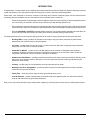
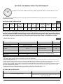
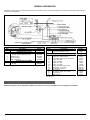
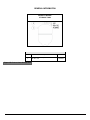
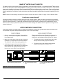
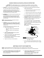
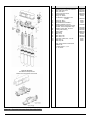
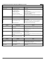
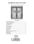
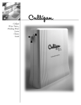
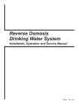
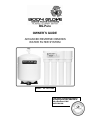
BG-Pure
OWNER’S GUIDE
ADVANCED REVERSE OSMOSIS
WATER FILTER SYSTEM
Model: WI-BG-PURE
This model is tested and certified
by WQA against NSF/ANSI 58 for
the reduction of TDS:
4VTFC25G-PB
Please fill in the following information and retain for reference:
Model Number:
WI-BG-PURE
Serial Number: _____________________________________
Date Purchased: ____________________________________
Date Installed: ______________________________________
INTRODUCTION
Congratulations, on the purchase of your new Body Glove Advanced Reverse Osmosis Water Filter System. With proper care and
regular maintenance, your new system will provide many years of service, delivering great tasting water.
Please take a few moments to review the contents of the Body Glove Reverse Osmosis System and this manual before
proceeding with the installation and use of the system. Some important items to review are:
o
Check all components for any damage caused in shipment. Also, take a quick inventory of all items supplied to ensure
none are missing. A checklist in the next section will assist you with identifying these items.
o
Ensure that the reverse osmosis system and storage tank will easily fit into the desired location. This reverse osmosis
system and tank needs to be accessed for regular maintenance, good accessibility is an important tip to keep in mind.
o
Read all CAUTIONS and NOTES contained within this manual. They provide valuable installation tips and advice on
how to properly install and maintain your Body Glove Reverse Osmosis Drinking Water System.
The water produced by the reverse osmosis (RO) process can be used for many purposes around the home and office.
o
Drinking Water - keep a container of RO water in the fridge to enjoy the clean, fresh taste of purified water.
Alternatively, take it directly from the faucet dispenser.
o
Ice Cubes - use RO water to fill ice cube trays. Ice cubes made from RO water are typically clearer and better
tasting than ice made from non-filtered tap water.
o
Automatic Ice Makers - a water line from the RO system can be plumbed to refrigerators with automatic
icemakers. Additional accessories required to complete this connection are not included. Please consult the
refrigerator manufacturer’s owner’s manual for this type of installation.
o
Kettles and Coffee Makers - tap water eventually causes films and scale in these devices that is difficult to clean
without the use of special cleansers. RO water is very low in dissolved minerals content, greatly reducing the
tendency of scale buildup.
o
Cooking - use RO water for food preparation and any recipe that calls for water.
o
Washing Fresh Fruit & Vegetables - prevent tap water minerals from being deposited onto food to maintain
freshness and to prevent off-tastes.
o
Family Pets – Allow your pets to enjoy the same great tasting water you do.
o
Irons & Steamers - prevent mineral buildup in household and office appliances that use water and eventually
build up with scale when using non-filtered tap water.
Now you can enjoy all the benefits of great tasting water supplied by your Body Glove reverse osmosis drinking water system.
I
CERTIFIED CONTAMINANT REDUCTION PERFORMANCE
Model 4VTFC25G-PB is tested and certified by WQA against NSF/ANSI 58 for the reduction of TDS
The following Body Glove BG-PURE Reverse Osmosis System conforms to NSF/ANSI 58 for the specific performance claims as verified and
substantiated by test data.
BG-PURE SYSTEM CONFIGURATION
Table 1
Model
Description
Storage
Tank
# of
Vessels
Storage
Tank
Capacity
Liters (gal)
Vessel
1
Vessel
2
Vessel
3
Vessel
4
Daily
Production
Rate(2) L/day
(G/day)
Efficiency
Rating(3) %
Recovery
Rating(4) %
Monitor(6)
4VTFC25G-PB
Plastic/Metal
4
7.19 (1.9)
Sediment
Filter
Carbon
Filter
TFC(1)
Membrane
Carbon
Filter
29.1 (7.7)
8.2
18
Smartap®
Push
Button
The manufacturer tested higher efficiency and recovery ratings using the 25 GPD TFC membranes with the Body Glove
BG-Pure. Stringent NSF/ANSI 58 testing criteria reported lower efficiency and recovery ratings, representing the worst
case tested scenarios. Under surrogate testing, using a storage tank with backpressure, the TDS reduction efficiency
percentage averaged 95% and the recovery rating percentage averaged 28.5% based on manufacturer test data.
CONDITIONS FOR USE
Table 2
Source Water Supply Profile
Community/Private
Chemical Parameters
Chlorinated/Non-Chlorinated
Feed Water Pressure
(5)
242-690 kPa (35-100 psi)
Temperature
4°-38° C (40°-100° F)
Hardness (CaCO3 )
Max mg/L
<350 (20 gpg)
Iron (Fe )
<0.1
Manganese (Mn)
<0.05
pH Range
3.0 - 11.0
Hydrogen Sulfide (H2S )
0.00
Maximum TDS Level
2000 mg/L
Residual Chlorine (Cl2)
<2.0
Turbidity**
<1.0 NTU
** Nephelometric Turbidity Unit
Maximum SDI***
*** Silt Density Index: Value stated in SDI units.
<4.0
NOTES:
1. TFC refers to reverse osmosis membranes constructed from a THIN FILM COMPOSITE.
2. The daily production rate is the volume of product water produced by the system per day and is determined by testing in accordance with the procedure
outlined in NSF/ANSI Standard 58.
3. System’s Efficiency rating as verified by testing in accordance with NSF/ANSI standard 58. Efficiency rating means the percentage of the influent water to
the system that is available to the user as reverse osmosis treated water under operating conditions that approximate typical daily usage.
4. System’s Recovery rating as verified by testing in accordance with NSF/ANSI Standard 58. System’s Recovery rating means the percentage of the influent
water to the membrane portion of the system that is available to the user as reverse osmosis treated water when the system is operated without a storage
tank or when the storage tank is bypassed.
5. PRESSURE REGULATOR IS RECOMMENDED FOR FEED WATER PRESSURES EXCEEDING 552 kPa (80 psi).
6. SMARTAP® PUSH BUTTON MONITOR. Indicator lights located on the module cover report system status.
OPTIONS AND ACCESSORIES
PRODUCT WATER FAUCETS
BOOSTER PUMP
A booster pump may be used if system pressure is below 242 kPa (35 psi).
Pump should be placed near RO Module and installed in feed water line just
before it enters Module.
Faucets will be supplied as Air Gap.
II
GENERAL INFORMATION
This Owner’s Guide covers all components that may be included with a system. Information relating to any component that is NOT included with your
system may be disregarded.
SYSTEMS WITH AIR GAP FAUCET, MODEL WI-BG-PURE
Item
1
2
3
4
5
6
REVERSE OSMOSIS SYSTEM
Description
4 Vessel Module, With Quality Monitor
MEMBRANE AND FILTERS
Reverse Osmosis TFC Membrane
25 GPD, Yellow Casing, Black Tape
Sediment Filter
Carbon Pre-Filter
Carbon Post Filter
FLOW RESTRICTOR TUBING
Flow Restrictor Tubing
25 GPD
Part No.
Fig 8
Item
7
8
33001068
41400008
41400009
41400009
9
10
11
12
13
14
n/s
n/s
n/s
n/s
n/s
n/s
n/s
40600040
PRODUCT WATER FAUCETS
Description
Chrome-Plated Metal, Air Gap
Connector, Faucet 3/8” x 7/16”
INSTALLATION KIT
Complete Kit
Supply Valve, Saddle-Tapping
Drain Clamp, Saddle Clamp, Air Gap, 3/8”
Tubing, 3/8”, Red
Tubing, 3/8”, Blue
Tubing, 3/8”, White
Tubing, 1/4", White
Screw, Mounting Bracket (2 each)
Elbow, Stem, 3/8” (2 each)
Elbow, Stem ¼” (2 each)
Owner’s Guide
Kit, O-Rings, Collets, QC ¼” & 3/8”
Safety Clip 1/4”
Safety Clip 3/8”
Part No.
92192, Fig 7
92407
n/s - not shown
Figure 1.A: Component* and Interconnection Locators, Model WI-BG-PURE
*Replacement parts can be obtained from Water, Inc. Refer to the service information on the last page of this manual.
III
92276
92160
87604
87600
115207
115200
32701006
33501071
33501064
36101291
92166
96345
92346
GENERAL INFORMATION
PRODUCT WATER
STORAGE TANK
PRODUCT WATER STORAGE TANK
Item
1
2
Description
Storage Tank Assembly, Metal
Ball Valve, 3/8”
Figure 1.B: Product Water Storage Tank.
IV
Part No.
92342/92294
33503601
INSTALLATION REQUIREMENTS
READ THIS ENTIRE INSTALLATION AND SERVICE GUIDE BEFORE BEGINNING INSTALLATION
The Body Glove Reverse Osmosis (RO) Drinking Water System has been designed for ease of installation and
serviceability and is constructed with the finest materials available. Using these instructions and paying close attention to
the parameters outlined within "CONDITIONS FOR USE" detailed on Page II will ensure a successful installation.
The Body Glove System must be installed in accordance with applicable city, state, provincial and local plumbing
codes. To ensure the system continues to operate at its optimum level, it is necessary to use a routine maintenance and
replacement schedule (See table 4 below). The frequency at which filters must be changed will depend on the quality of
feed water supply and the level of system usage.
The Body Glove RO system contains replaceable filter components critical to the efficiency of the system.
Replacement of the reverse osmosis filter components should be with one of identical specification, as defined by Water,
Inc. to assure the same efficiency. Product water shall be tested periodically to verify the system is performing properly.
®
The Body Glove RO operator may perform the periodical water test using the Smartap Water Quality Monitor.
All state, provincial and local government codes regarding installation of these devices must be observed.
PREPARATION
2. Determine location for RO component installation.
Two requirements for consideration are: access to
cold water supply line and household sink drainpipe.
Specific requirements are detailed in Table 3.
1. Check that all appropriate components are packed
with your system (Figures 1.A. and 1.B., pgs. III & IV).
COMPONENT LOCATION REQUIREMENTS
Table 3
PRODUCT WATER FAUCET
Faucet may be installed in any convenient location.
Make sure underside of location is free of obstructions.
REVERSE OSMOSIS MODULE
Module may be installed under sink or in any convenient
location within 15 feet of source water supply and faucet.
STORAGE TANK
Tank may be placed in any space within 15 feet of faucet, generally under kitchen sink or in an adjacent unused cabinet.
Tubing length between components should be kept to a minimum, avoiding sharp bends or kinks.
DO NOT PLACE MODULE WHERE IT WILL BE EXPOSED TO FREEZING AND/OR DIRECT SUNLIGHT.
MODULE MUST BE EASILY REMOVABLE FOR PERFORMANCE OF ROUTINE MAINTENANCE.
Mount Module on side of cabinet using bracket (attached to Module) and two screws provided in the Installation Kit.
HOLD THE MODULE BY THE FILTER HOUSINGS WHEN PICKING UP OR CARRYING UNIT.
NOTE
THIS BODY GLOVE DRINKING WATER SYSTEM IS FOR USE ON POTABLE WATER SUPPLIES ONLY.
SOURCE WATER EXCEEDING CHEMICAL PARAMETERS REQUIRES PRE-TREATMENT.
CAUTION
DO NOT USE WITH WATER THAT IS MICROBIOLOGICALLY UNSAFE OR OF UNKNOWN QUALITY
WITHOUT ADEQUATE DISINFECTION BEFORE OR AFTER THE SYSTEM.
BODY GLOVE RO MAINTENANCE REQUIREMENTS
Table 4
Service Requirements
Recommended Service Intervals
To insure the system operates at its optimum level, certain routine
maintenance must be performed. Frequency of maintenance performance
will depend on feed water quality and level of system usage.
Replace filters as required or every 6 to 12 months
depending on feed water quality.
CLEAN: Each time filters are replaced
Replace membrane as required based on Smartap®
Water Quality Monitor indication or periodic TDS rejection tests.
SANITIZE: At least once a year and each time membrane is replaced.
Maximum recommended service life for membrane is 60 months.
1
SMARTAP® WATER QUALITY MONITOR
®
The Body Glove Reverse Osmosis System incorporates a proven performance indicator. Our patented Smartap Water Quality
Monitor uses dual probe LOGIC PULSE MEMORY technology to accurately indicate membrane performance. A split-second
power pulse compares the feed water Total Dissolved Solids (TDS) level with that of the product water. Then, by reversing the
polarity of the electronic pulse, the probes are cleaned and kept free of chemical plating. A nine-volt alkaline battery provides
power to the Monitor. For optimum monitor performance, the battery should be replaced each time system is sanitized (or once a
year).
NOTE: Monitor Troubleshooting Indicators and Common Solutions are shown in Table 5 on page 12 of the Owner's Guide..
Push Button Actuated Smartap®
Pressing a test button located on the Body Glove RO cover activates monitor. When the button is pressed, and momentarily
held down, the monitor reports the membrane status by illuminating a light located next to test button. A green light means the
system is operating normally. A yellow light indicates the system needs servicing (membrane may be depleted or fouled).
While the button may be pressed at any time, the most accurate readings are obtained when the system is making water for
at least 10 minutes.
INTER-COMPONENT CONNECTIONS
Connections between cold water supply line, Body Glove RO Module, storage tank, product water faucet and drain line are
accomplished using plastic tubing and push-together quick-connect type fittings.
PLASTIC TUBING
QUICK-CONNECT FITTINGS
1. Cut tube ends square and straight. Do not deform
tube (i.e., cause tube to compress its diameter so it
is no longer round).
Fittings consist of two parts: a Body and a colored collet
and symbol. Collet color and symbol corresponds to
tubing to be used at that connection (Figure 2.A. below).
2. Make sure outer surface of tube is clear of marks or
scratches for a length equal to twice tube diameter.
This allows "O" ring to seat properly against tube.
1. To install a tube, push it through Collet until it seats
firmly at bottom of fitting (Figure 2.A and 2.B.).
2. To remove a tube, push and hold Collet against
Body while pulling tube out (Figure 2.C.).
3. Avoid sharp changes in direction when routing
tubing. Sharp turns cause tubing to flex and deform,
which reduces flow capacity and may increase
lateral stress on the fittings, causing leakage.
A. Push tube through Collet into Body.
Figure 2:
B. Tube must seat firmly at bottom of
fitting.
How to Use Quick-Connect Fittings
2
C. Push Collet against Body and pull
tube to release.
SADDLE-TAPPING VALVE INSTALLATION ON COPPER TUBE
CAUTION: This saddle-tapping valve is not designed for installation on flex line tubing.
NOTE: State, provincial and local plumbing codes may prohibit use of saddle-tapping valves.
4. Connect source water feed tubing to valve body
using compression fitting.
1. CAUTION: If no shut off valve is installed under
sink, close main water valve during this Installation.
a. Slide nut and sleeve onto tubing (in that order).
Locate shut off valves on water lines under sink. To
identify hot supply pipe and cold supply pipe, turn
both faucets on and let water run. As water flows, the
hot water pipe becomes noticeably warmer.
b. Install insert into plastic tubing.
c.
Install tube with insert and sleeve into valve body.
d. Thread compression nut onto valve body, tighten.
2. CAUTION: Do not install feed water assembly on the
hot water line.
Turn off cold water supply by closing shut off valve.
Drain the water line by opening sink faucet. Some
mixing-type faucets may require hot water supply be
shut off as well.
5. Turn saddle-tapping valve handle clockwise until it is
firmly seated and piercing lance is fully extended.
6. CAUTION: Supply line is pierced and valve is closed.
Do not open valve until system is activated (See
Activating the System, page 9).
NOTE: All instructions refer to components shown in
Figure 3 unless otherwise noted.
Turn on cold water supply. Check saddle-tapping
valve installation for leaks. Allow water to run from
faucet for a few minutes to clear any debris in the line
caused by installation.
3. CAUTION: Do not turn valve handle before or while
installing saddle-tapping valve. Make sure piercing
lance does not protrude beyond rubber gasket before
installing valve.
NOTE: If flow from sink faucet is reduced, clean
faucet aerator.
Assemble saddle-tapping valve assembly on tube.
a. Hold back plate against tube.
• 3/8" copper tubing use back plate smaller
radius.
• 1/2" copper tubing, use back plate larger
radius
LARGER RADIUS
TIGHTENING
SCREW
VALVE SADDLE
STEM SEAL NUT
REVERSIBLE
BACK PLATE
b. Hold valve saddle against tubing in a position
directly opposite back plate.
c.
EXISTING 1/2"
COPPER TUBING
HOUSEHOLD
COLD WATER LINE
SMALLER RADIUS
VALVE HANDLE
VALVE BODY
COMPRESSION
NUT
INSERT
Tighten screw enough so valve saddle and back
plate are held securely against tube.
SLEEVE
d. Rotate assembly so tubing connection is aligned
toward RO Module feed port.
Figure 3:
e. Tighten screw firmly. Do not crush tube.
TUBING TO MODULE
(1/4" WHITE TUBING
Saddle-Tapping Valve Assembly
P/N 92276 installed on
1/2” Copper Tubing
7. Trim ¼” white tube to desired length. Install ¼” white
tube into ¼” white collet as shown in Figure 1.A (page
111).
ADDITIONAL POINT OF USE CONNECTION
NOTE: Icemakers typically use 1/4" tubing as feed line. Use a reducing union for this connection.
NOTE: Reduce the 3/8” line to 1/4” as close as possible to the additional point-of use device to minimize flow loss.
1. To connect an additional point of use (icemaker, extra
faucet in wet bar and/or another use for treated water),
place a "tee" connector in 3/8" blue line between
faucet and RO Module.
2. Connect "tee" to point-of-use with 3/8" blue tubing.
Connect tubing to point-of-use.
Connector requirements are based on type of
delivery device i.e., a typical icemaker uses
3/8" x 1/4" reducing union.
3
DRAIN OUTLET ASSEMBLY INSTALLATION
NOTE: State, provincial and local plumbing codes may prohibit use of saddle-tapping drain connections and may
require use of an air gap.
NOTE: Location and orientation of drain outlet assembly is vital to system performance.
Horizontal Drain Line:
Locate drain hole as close as possible to top of pipe
(between 45º and top) and as far as practical from
garbage disposal.
Figure 4:
Vertical Drain Line:
Locate drain hole on a straight length of drainpipe next to
"P"/"S" trap between trap and sink.
Drain Hole Location and Installation, Air Gap Faucet
NOTE: See Page III, Figure 1.A. for connection to drain for Non-Air Gap Faucet.
1. Select a location for drain hole based on type of sink
and orientation of drain line (Figure 4).
2. Position drain outlet saddle (Figure 5, Item 1) on
drainpipe. Allow adequate space for drilling operation.
3. Tighten saddle bolts evenly on both sides. Avoid overtightening.
4. Using opening in drain saddle outlet as a guide, drill a
3/8" to 7/16" diameter hole in drainpipe. Clean any
debris out of drain saddle connection.
Item
1
Description
Drain Saddle, Air Gap, 3/8” Connection
Figure 5:
4
Drain Outlet Assembly
Part No.
92160
PRODUCT WATER FAUCET SITE PREPARATION
Refer to Faucet Installation Instructions (Page 6) for site location and mounting hole specifications.
Primary considerations for site selection are convenience of use and an open area under sink. An existing 7/8”
Sink Hole will also accommodate metal faucets with air-gap connections. Always check underside of selected
location for obstructions.
STAINLESS STEEL SINK
PORCELAIN/ENAMEL OVER STEEL
OR CAST IRON SINKS
1. Use a center punch to make a small indentation to
mark center of desired location.
1. CAUTION: A heavy duty, variable speed drill motor
with a spring-loaded porcelain drill set (Figure 6) is
strongly recommended for this procedure.
2. Drill a pilot hole with a 1/8" metal drill bit, then enlarge
hole with a 3/8" metal drill bit.
CAUTION: The plastic sleeve supplied on pilot drill
(Figure 6.A) is to be positioned on drill bit against drill
chuck. This prevents chuck from contacting
porcelain after pilot hole has been completed.
3. Complete hole size by using a 1-1/4” chassis punch.
4. Installation hole is ready, install faucet.
NOTE: Practice on discarded sinks to familiarize
yourself with operation of porcelain cutter kit.
A.
PILOT DRILL
B.
SPRING LOADED PORCELAIN SAW
C.
FINISH HOLE SAW
Using carbide tipped bit with plastic sleeve (Figure
6.A.), drill pilot hole completely through porcelain and
metal underneath.
2. CAUTION: Avoid high motor R.P.M. during initial
penetration of porcelain, as high drill speed will cause
excessive chipping.
Place spring-loaded porcelain saw (Figure 6.B.) into
drill chuck. Make sure pilot guide is inserted tightly.
Insert pilot guide into pilot hole. Push down gently on
drill motor to apply light pressure to porcelain surface.
Start drill motor turning as slowly as possible.
After initial cut has started, motor speed may be
gradually increased. The cut may require three to
four minutes to complete. Going faster could result in
excessive chipping. Be sure a complete ring has
been cut through porcelain to material underneath.
3. Place finish hole saw (Figure 6.C.) into drill chuck.
Make sure pilot guide is inserted tightly. Insert pilot
guide into pilot hole. Begin cut using a slow speed
and light pressure until porcelain (inside ring cut in
Step 2) has been penetrated to material underneath.
4. Remove saw from hole and clean all debris from
porcelain surface. Re-insert saw into hole and cut
through remaining material.
5. Installation hole is ready, install faucet.
TILE COUNTER TOP
1. Follow procedures detailed in section labeled
"Porcelain/Enamel Over Steel" (substitute "tile" for
"Porcelain" in instructions).
Figure 6
5
METAL PRODUCT WATER FAUCET INSTALLATION AND SYSTEM CONNECTIONS
Install faucet on flat surface at least 2" in diameter. Unused 1-1/4" hole is ideal.
Steps unique to a specific configuration are so noted. All other steps are common to either configuration.
New Faucet Installation
Refer to Faucet Site Preparation, Page 5.
8. CAUTION: Red 3/8" tube connecting product water
faucet to drain saddle must run vertically (or as
closely as possible) with no sharp bends or loops
(See Page 4, Figure 4).
Replacement Faucet Installation
Verify size of existing hole is 1 1/4".
Connect loose ends of tubing as follows:
a. Non-Air Gap Only: Connect 1/4" FLR red tubing
to 1/4" drain saddle using compression nut.
b. Air Gap Only: Connect 3/8” red tubing to
3/8" on drain saddle using compression nut.
NOTE: Item callouts refer to Page 7, Figure 7 unless
noted otherwise.
1. Air Gap Only: Verify faucet body, metal base
washer, and rubber base washer are in place above
sink (Items 1, 3, and 2).
Non-Air Gap Only: Verify faucet body, metal base
washer, and rubber base washer are in place above
sink (Items 1, 3, and 2).
Refer to steps 2-4 in Polymer Tank Assembly for use
of compression nuts.
Storage Tank Connection - Metal Tank Assembly
2. CAUTION: Flow Restrictor (FLR) is installed inside
the 1/4” red tubing on the end with the label. DO NOT
TRIM THE END OF THE 1/4" FLR
RED TUBING THAT INCLUDES
THE LABEL (See Figure 8.A/B).
NOTE: The following instructions refer to Page IV,
Figure 1.B, Items 2 & 3.
NOTE: Refer to Page 2, Inter-Component Connections
for instructions on how to install tubing.
Air Gap Only: Install 3/8” red tubing from
Installation Kit onto larger hose barb as shown in
Figure 7.
1. Install ball valve (located inside of master pack box)
onto the 1/4” storage tank nipple. Use thread sealing
tape to seal threads between ball valve and nipple.
2. Connect 3/8” white tubing between module
(near symbol as shown) and storage tank
shut-off valve.
3. The basic installation is complete and
system is ready for activation (see Page 9).
3. Air Gap Only: Connect the 1/4” FLR red
tubing end with FLR label between the
module red collet near symbol shown
and the faucet:
a. Air Gap Only: Insert the 3/8” red tube into the
mounting hole.
b. Air Gap Only: Insert the 1/4" FLR red tubing
upwards through mounting hole.
c. Air Gap Only: Position module in desired
location. Trim the end of FLR tubing without label
to desired length. Attach FLR tubing onto smaller
hose barb as shown in Figure 7.
NOTE: With the storage tank empty, ensure the air-cell
pre-charge is set to manufacturer’s instructions marked
on tank. Use a hand power air pump to increase, if
necessary.
WARNING: Never use an air compressor to fill air cell of
a reverse osmosis system storage tank. Damage to the
tank and/or air cell can occur.
4. Lower faucet into mounting hole and place
faucet over hole.
NOTE: Optional stem elbows have been
supplied to allow installations with limited
space. Connect the stem elbow into the
inlet, faucet, tank and drain parts as
required before connecting tubing.
5. Air Gap Only: Install slotted washer, spacer, faucet
washer, and nut onto faucet nipple below sink and
snug them up (Items 4, 5, 6, and 7). Be sure to
properly align faucet before tightening. Do not over
tighten.
Non-Air Gap Only: Install locating washer, faucet
washer and nut (Items 4A, 6, and 7) onto faucet
nipple below sink and snug them up. Be sure to align
faucet properly before tightening. Do not over tighten.
6. Install faucet connector (Item 8), packaged with
faucet, onto faucet nipple. Install 3/8” blue tube into
faucet connector.
7. Trim 3/8” blue tube to desired length. Install
3/8” blue tube into 3/8” blue collet located on
side of module near symbol as shown.
6
Description
Chrome Plated Metal Air Gap Faucet
(USEPA Compliant and California SB 1953
Compliant)
Part No.
Item
40301001 or
92192
Description
1
Body, Faucet
2
Faucet Base Washer, Rubber
3
Faucet Base Washer, Metal
4
Washer, Slotted (Air Gap, Slot Shape may vary)
4A
Washer, Locating (Non-Air Gap, Replaces Items 4 and 5, not
shown)
Figure 7:
Chrome-Plated Metal Product Water Faucet Assembly
7
5
Spacer, Faucet (Air Gap)
6
Washer, Faucet
7
Nut, Faucet
8
Connector, Faucet 3/8” x 7/16”
MODEL WI-BG-PURE
Item
1
2
3
4
5
6
7
8
9
10
11
12
13
14
15
16
17
18
19
n/s
n/s
n/s
Description
BG-PURE Cover, Push Button Manifold
Screw, inlet Valve Cover
Cover, Inlet Valve
"O" Ring, Inlet Valve Cover
Shut Off Assembly
Tubing, 1/4”, White *
Flow Restrictor, 1240 Series, Red
25 GPD
Tubing, 3/8”, Blue *
Tubing, 3/8”, White *
RO, 4V Manifold, Assembled **
Cartridge, Sediment, 5 micron
Filter, Membrane Thin Film Composite
25 GPD, Yellow Casing Black Tape
Cartridge, Carbon AES, 10 micron
"O" Ring, Filter Housing
Housing, Filter
Circuit Board
Battery 9 volt
Elbow, Stem, 3/8” *
Elbow, Stem, 1/4” *
Kit, O-Rings, Collets, QC, ¼” & 3/8”
Safety Clips ¼”
Safety Clips 3/8”
*Note: These parts are included with
installation kit.
** Includes Items: 2, 3, 4, 5.
n/s – not shown
Model WI-BG-PURE
Push Button Smartap® Monitor
Module Cover and Monitor Connections
Figure 8:
Exploded Schematic, Body Glove BG-PURE
8
Part No.
20500127
32701038
20500126
34201024
40600010
115200
40600040
87600
115207
12402
41400008
33001068
41400009
34201026
20500129
40200132
701085
33501071
33501064
92166
92345
92346
ACTIVATING THE SYSTEM
CAUTION: Make sure all water supply lines, drain lines and fittings are secure and free from leakage.
1. Open source water supply valve. Close product water
faucet. Check for leakage.
8.
Open product water faucet and let water flow until all air
has been expelled from system.
2.
Turn tank valve one-quarter turn counter-clockwise to
open valve (handle should be in line with tubing as it
enters connection).
9.
Close product water faucet. In 30 minutes, check
connections for leaks and correct if necessary.
3.
Confirm system is producing water. Module will be
sending rinse water to drain.
4.
Remove manifold cover if attached by gently lifting
cover up and away from manifold.
Icemaker/Extra point of use: Check connections on
these supply lines for leaks.
10. Allow storage tank to fill overnight.
11. WARNING: DO NOT USE THE FIRST FULL
STORAGE TANK OF WATER
CAUTION: Wiring within module cover connects
monitor components. If wires, circuit board, or
connections are damaged and/or wetted, monitor will
not function.
5.
Discard (to drain) first full tank of water by opening
product water (and extra point-of-use) faucet until water
flow stops, then close faucet. This will flush sanitizing
solution from system.
CAUTION: Verify battery connector alignment
before making connection (Page 11, Figure 9).
Icemaker: Let tray/bin fill with ice cubes. Discard all
ice cubes. This flushes sanitizing solution from lines to
icemaker.
Connect battery on manifold by pressing clip onto
battery terminals.
6.
Replace manifold cover by gently pushing cover onto
manifold until it snaps into place.
7.
Test battery connection by activating monitor. Press
push button. If either indicator light illuminates,
connection is good.
12. System is ready to use. Should there be any aftertaste
or odor to water or ice cubes, repeat Steps 10 and 11.
NOTE: Release button after light illuminates. Test is to
confirm battery connection, not water quality.
DO NOT USE THE FIRST STORAGE TANK OF WATER
Allow storage tank to fill overnight. Dispense this water to drain.
This process removes factory-installed sanitizing solution from the entire system and sends it to drain.
This process also sanitizes fittings and tubing used during installation.
MAINTENANCE PROCEDURE PREPARATION
RECOMMENDATIONS
HAVE ALL EQUIPMENT AND REPLACEMENT COMPONENTS ON HAND AND READY BEFORE BEGINNING PROCEDURE.
A CLEAN WORK AREA AND EQUIPMENT ARE ESSENTIAL TO PROPERLY CLEAN AND/OR SANITIZE THE SYSTEM.
(i.e., CLEAN HANDS, TOOLS, WORK SURFACE, AND CONTAINERS)
EQUIPMENT NEEDED
Safety glasses
Rubber gloves, sanitary
Wash Cloth, Clean and Lint-free
Liquid dish soap
Household bleach - Unscented Only
(5.25% sodium hypochlorite)
Plastic storage bag
Manual Air Pump
9
Plastic bucket
Plastic bowl
“O” ring Lube FDA Approved
CLEANING, SANITIZING, AND CARTRIDGE REPLACEMENT PROCEDURE
1. Mix mild cleaning solution of dish soap and clean
potable water in plastic bowl.
Clean filter housings and manifold ports, inside and
outside, with washcloth and cleaning solution. Do
not use abrasive materials.
2. Empty storage tank and relieve system pressure.
Verify tank valve is open. Close feed water supply
valve and open product water faucet.
9. Rinse manifold/housings with clean potable water.
10. Inspect manifold and filter housing "O" ring groove
area for damage (i.e., nicks or scratches). Replace
damaged components.
Icemaker: Transfer ice cubes from bin/tray to clean
freezer container for storage until procedure is done.
3. CAUTION: Only use air hand pump to avoid
damaging tank. Verify product water valve is open
before proceeding.
11. Place a small amount of "O" ring lubricant over
surface of filter/membrane housing "O" ring. Install
"O" ring into filter housing groove.
Check product water storage tank air pre-charge
using a low-pressure gauge (e.g. 0 -15 or 0 – 30 psi).
Air valve is located on tank base. Pre-charge should
be 55 kPa (8 psi) with tank empty and tank valve
open.
TO SANITIZE THE SYSTEM: Complete Steps 12-34.
TO INSTALL FILTERS: Complete Steps 19-34.
WARNING: WEAR SAFETY GLASSES WHILE
PERFORMING THIS PROCEDURE.
4. CAUTION: Do not attempt to remove filter housings
until water flow stops. This reduces pressure inside
the system so housings may safely be removed.
READ "WARNINGS" INFORMATION ON BLEACH
CONTAINER BEFORE USING CONTENTS.
HANDLE SANITIZING SOLUTION CAREFULLY.
AVOID CONTACT WITH UNPROTECTED AREAS.
CAUTION: Additional point-of-use devices (i.e.,
icemakers) may use filters along their supply line.
Remove any filter or treatment device installed
between module and device before proceeding.
12. CAUTION: Excessive concentrations of bleach will
damage plastic and rubber components. Rinse all
parts that contact bleach thoroughly with clean
potable water.
Remove each filter/membrane housing by turning it
counter-clockwise. Remove each filter cartridge as its
housing is removed. Discard filters.
Mix sanitizing solution of 1.5 ml (1/3 teaspoon) of
household bleach and 3.8 L (1 gallon) of clean,
potable water in the bucket. Mix solution well.
IF MEMBRANE IS PERFORMING SATISFACTORILY:
Proceed to Step 5.
IF MEMBRANE IS DEPLETED OR FOULED:
Discard it and go to Step 7.
13. CAUTION: Tighten filter housings by hand only. Do
not use tools as they will over-tighten and damage
housings. Take care not to cut or pinch o-rings.
5. CAUTION: Use sanitary rubber gloves for this
procedure to avoid contaminating sanitizing solution,
filters, or membrane. Wear gloves whenever
cleaning/ sanitizing system components or handling
new filter/membrane cartridges.
Add 236 ml (one cup, 8 oz.) of sanitizing solution to
each filter housing and install them onto the manifold
(do not install filters or membrane at this time).
Tighten each filter housing by hand only.
Clean membrane outer wrap with washcloth and
cleaning solution. Do not immerse membrane in
solution. Do not scrub membrane wrap with abrasive
cleaners. Rinse membrane well with clean potable
water.
14. Slowly open source water supply valve.
15. Open product water faucet. Close faucet as soon as
water begins to flow from spout.
16. Wait 5 minutes, then close source water supply
valve.
6. Place membrane into clean plastic bag, close bag.
7. Remove filter/membrane housing "O" rings and wash
them with cleaning solution. Rinse them well with
clean potable water. Inspect them for damage (i.e.,
nicks, scratches). Replace damaged "O" rings.
17. Wait 25 minutes, then open product water faucet and
let water flow to drain.
18. CAUTION: Do not attempt to remove filter housings
until water flow stops. This reduces pressure inside
the system so housings may be removed safely.
®
8. CAUTION: Do not allow the Smartap Water Quality
Monitor electronics, wiring, or connectors to get wet.
Remove filter housings and dispose of water. Rinse
filter housings and manifold ports thoroughly with
clean potable water.
10
CLEANING, SANITIZING, AND CARTRIDGE REPLACEMENT PROCEDURE (cont.)
19. CAUTION: Do not remove protective plastic bag from
replacement filter/membrane cartridges until
instructed.
28. Test battery connection by activating monitor. Press
push button. If an indicator light illuminates,
connection is good.
Install "O" rings into filter housings. Open top of filter
bag enough to expose filter cap and "O" ring grooves.
Place a small amount of "O" ring lubricant on surface
of each "O" ring.
29. Replace manifold cover by gently pushing manifold
cover onto manifold until it snaps into place.
20. CAUTION: Tighten filter housings by hand only. Do
not use tools as they will over-tighten and damage
housings. Take care not to cut or pinch o-rings.
30. Open product water faucet. Let water flow until all
air has been expelled from the system.
31. Close product water faucet. Wait 30 minutes, check
connections for leaks, and correct if necessary.
CAUTION: Refer to Page 8, Figure 8.B. for
location of each cartridge.
Icemaker/Extra point of use: Check lines for leaks.
Install filter and membrane cartridges. Hold cartridge
by its protective plastic bag and insert cartridge into
manifold turning it 1/4 turn as it enters the port. Slide
bag from cartridge and discard. Replace each filter
housing as each cartridge is installed.
32. Allow storage tank to fill overnight.
33. WARNING: DO NOT USE THE FIRST FULL
STORAGE TANK OF WATER
21. Turn feed water valve slowly to open position.
Discard (to drain) first full tank of water by opening
product water faucet until water flow stops, then
close faucet. This flushes sanitizing solution from
system.
22. Confirm system is producing water. Unit will be
sending rinse water to drain.
Smartap® Water Quality Monitor
Icemaker: Let tray/bin fill with ice cubes. Discard all
ice cubes to drain. This flushes sanitizing solution
from lines to icemaker. Replace delivery device filter
(if applicable).
TO REPLACE BATTERY: Perform Steps 23 – 29
NOTE: Replace battery with a new alkaline 9-volt battery.
23. CAUTION: Wiring within module cover connects
monitor components. If wires, circuit board, or
connections are damaged and/or wetted, monitor will
not function.
34. System is ready to use. Should there be any after
taste or odor, drain storage tank and repeat Steps 32
and 33.
Remove module cover by gently lifting manifold cover
up and away from manifold body.
24. Disconnect battery. The battery connection is a snap
type connector (Figure 9).
25. Remove battery by sliding it out of its holder.
®
Figure 9: Smartap Battery Connections
26. Slide new battery into its holder.
27. CAUTION: Verify battery connector alignment
before making connection (Figure 9).
DO NOT USE THE FIRST
FULL STORAGE TANK OF WATER
Connect battery by pressing clip onto battery
terminals.
Allow reservoir to fill overnight.
Dispense this water to drain.
This process removes sanitizing solution from system,
sanitizes fittings and tubing, and sends solution to drain.
NOTE: Release button immediately after light
illuminates. Test is to confirm battery connection,
not water quality.
11
TROUBLESHOOTING INDICATORS AND COMMON SOLUTIONS
Table 5
WATER VOLUME AND QUALITY
Symptom
Condition
Action
No product water.
Water supply is turned OFF.
Turn water ON.
Not enough product water.
Low water pressure.
Water supply is blocked.
Storage tank valve is closed.
Storage tank is depleted.
Check source water line pressure.
Clear restriction.
Open storage tank valve.
Increase product water storage capacity and/or install membrane
and flow restrictor with higher output rating.
Replace Pre-filter cartridge(s).
Empty water from storage tank (product water valve must remain open
while adjusting pressure) and adjust pressure to 55 kPa (8 psi).
Clogged Pre-filter cartridge(s).
Storage tank air pressure charge is low.
System does not shut off.
Shut-off valve is not closing.
Contact Water, Inc. Service Department
No drain water.
Clogged Flow Restrictor.
Replace Flow Restrictor.
Water has offensive taste and/or
odor.
Carbon post-filter is depleted.
Drain storage tank, sanitize system, and replace carbon
post-filter cartridge.
Membrane depleted or fouled.
Smartap® Monitor reads yellow, or if TDS test is unsatisfactory,
drain storage tank, sanitize system, and replace membrane.
Sanitizer not flushed out.
Drain storage tank and let it refill overnight.
LEAKAGE AND NOISE
Symptom
Probable Cause
Solution
Leak at fitting.
Tubing not pushed completely into fitting.
Defective tube.
Push tube into fitting past “O” ring seal.
Cut damaged area from tube or replace tube (See Page 2, Figure 2).
Leak at filter housings.
“O” ring has not seated properly.
Remove “O” ring and inspect “O” ring groove for debris. Clean groove,
lube, and reseat “O” ring.
“O” ring has nicks or scratches.
Replace “O” ring.
Restricted drain tube.
Clear restriction.
Obstructed hole in drain clamp
Remove obstruction.
Tubing from air gap to drain is routed
incorrectly.
Reroute tubing so tubing runs vertically with no sharp bends or loops
(see Page 4, Figure 4).
Trapped air in system. Typical of new
system or as a result of filter changes.
Nothing, system usage will purge trapped air.
Leak from air gap in faucet.
Noise from system and/or faucet air
gap.
PUSH BUTTON ACTUATED SMARTAP® WATER QUALITY MONITOR
Indication
Condition
Action
Green Light.
System operating normally.
None.
Yellow Light.
Low or non-usage.
Draw enough water from product water faucet to get system into
making water. Wait 10 minutes, test.
Membrane depleted or fouled.
Clean and sanitize system. Replace membrane.
Battery voltage low.
Replace Battery.
Dim or No Light.
12
LIMITED WARRANTY
Subject to the conditions and limitations described below, Water, Inc. warrants its Model BG-PURE Reverse Osmosis
Drinking Water Treatment System (excluding membrane, cartridge filters and battery), when installed in accordance with
Water, Inc. specifications, to be free from defects in materials and workmanship under normal use within the operating
®
specifications for a period of two (2) years from the date of purchase. Water, Inc. also warrants the Smartap Water Quality
Monitor to be free from defects in materials and workmanship under normal use within the operating specifications for a
period of five (5) years from the date of purchase. This warranty shall apply to the original end-user of the system only.
Other than the membrane, cartridge filters and battery, any part found defective within the terms of this warranty will be
repaired or replaced by Water, Inc. If any part is found defective, Water, Inc. also reserves the right to replace the drinking
water appliance with a comparable Water, Inc. drinking water system of equal or greater quality. You pay only freight for
repaired or replaced parts from our factory and local dealer charges, including but not limited to labor charges, travel and
transportation expenses and handling fees.
This warranty shall not apply to any part damaged by accident, fire, flood, freezing, act of God, bacterial attack (non-potable
water), membrane fouling and/or scaling, sediment, misuse, misapplication, neglect, alteration, installation, or operation
contrary to our printed instructions, or by the use of accessories or components which do not meet Water, Inc. specifications.
If the drinking water system is altered by anyone other than Water, Inc. the warranty shall be void.
ALL IMPLIED WARRANTIES, INCLUDING WITHOUT LIMITATION WARRANTIES OF MERCHANTABILITY AND
FITNESS FOR PARTICULAR PURPOSE, ARE LIMITED TO THE DURATION OF THE PERIOD SPECIFIED ABOVE FOR
THE PARTS DESCRIBED IN THIS LIMITED WARRANTY.
Water, Inc. does not know the characteristics of your water supply. The quality of water supplies may vary seasonably or
over a period of time. Your water usage may vary as well. Water characteristics can also change if the drinking water
appliance is moved to a new location. For these reasons, we assume no liability for the determination of the proper
equipment necessary to meet your requirements, and we do not authorize others to assume such obligation for us. Further,
we assume no liability and extend no warranties, expressed or implied, for the use of this product with a non-potable water
source or a water source which does not meet the conditions for use as described in this Owner’s Guide.
WATER, INC.’S OBLIGATIONS UNDER THIS WARRANTY ARE LIMITED TO THE REPAIR OR REPLACEMENT OF THE
FAILED PARTS OF THE DRINKING WATER SYSTEM, AND WE ASSUME NO LIABILITY WHATSOEVER FOR DIRECT,
INDIRECT, INCIDENTAL, CONSEQUENTIAL, SPECIAL, GENERAL OR OTHER DAMAGES, WHETHER FROM
CORROSION OR OTHER CAUSES.
Some states do not allow limitations on how long an implied warranty lasts, so the above limitations may not apply to you.
Similarly, some states do not allow the exclusion of incidental or consequential damage, so the above limitation or exclusion
may not apply to you. This warranty gives you specific legal rights, and you may have other rights that vary from state to
state.
Distributed Internationally by:
For parts and service, contact:
Water, Inc. Service Department:
1-800-322-WATER (9283)
1-800-322-WATER (9283)
Extensions 115 or 132
Register your product online
at: www.waterinc.com
© 2009 Water, Inc.
WI-925 Rev. 12-09