1
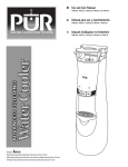
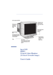
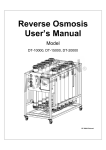
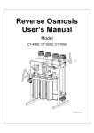
US Item# 1001 104 025 CAN Item# 1000803664 US Model #HDGROS4 CAN Model #HCGROS5 USE AND CARE GUIDE PREMIUM DEFENSE REVERSE OSMOSIS DRINKING WATER FILTRATION SYSTEM Questions, problems, missing parts? Before returning to the store, call Glacier Bay Customer Service 7 a.m. - 6 p.m., CST, Monday - Friday 1- 800800- 247247 -1087 HOMEDEPOT.COM/GLACIER HOMEDEPOT.COM /GLACIERBAY /GLACIERBAY System tested and certified by NSF International against NSF/ANSI Standards 42 & 53, for the reduction of the claims specified on the performance data sheet. NSF ® 201-8401424 (Rev 00) THANK YOU We appreciate the trust and confidence you have placed in Glacier Bay through the purchase of this filtration system. We strive to continually create quality products designed to enhance your home. Visit us online to see our full line of products available for your home improvement needs. Thank you for choosing Glacier Bay! Table of Contents Reverse Osmosis water flow schematic and description ............................................... 18 Maintenance ........................................ 19 Prefilter / Postfilter Maintenance ............. 19 Reverse Osmosis Membrane Cartridge Maintenance ............................................ 19 Reverse Osmosis Cartridge Replacement 19 Prefilter / Postfilter Cartridge Replacement19 Flow Control ............................................. 20 Changing the Collet and O-Ring ............... 20 Changing the Battery ............................... 20 Troubleshooting .................................. 21 Service Parts ....................................... 22 Safety Information .................................2 Warranty .................................................2 Pre-Installation ......................................3 Before You Begin This Installation ............. 3 Installation Location ................................... 3 Dimensions ................................................ 4 Specifications ............................................ 4 Tools Required ........................................... 5 Preparing the Site for Installation .............. 5 Package Contents ...................................... 6 Installation .............................................7 How the RO Water System Works .....17 Safety Information CAUTION:: Do not install the filtration system outside, or in extreme hot or cold temperatures. Temperature of the water supply to the filtration system must be between 40°F and 100°F. Do not install on a hot water line. Read all instructions before installing and using your reverse osmosis water filtration system. Follow all steps exactly to correctly install. Reading this manual will also help you to get all the benefits from the filtration system. NOTICE:: This filtration system works on water pressures of 40 psi (minimum) to 100 psi (maximum). If your house water pressure is over the maximum, install a pressure reducing valve in the water supply pipe to the filtration system. All plumbing must be completed in accordance with national, state and local plumbing codes. Local code information can be obtained at your local public works department. In Massachusetts, plumbing code 248 CMR 3.00 and 10.00 shall be adhered to. Consult with your licensed plumber. NOTICE:: Commonwealth of Massachusetts plumbing codes do not permit the use of saddle valves and require installation by a licensed plumber. Comply with plumbing code 248-CMR for installations in the state of Massachusetts. Please consult your local plumber. WARNING:: Do not use with water that is microbiologically unsafe or of unknown quality without adequate disinfection before or after the system. WARNING:: Do not use for the treatment of water that is visually contaminated (cloudy) or has an obvious contamination source, such as contamination by raw sewage. Warranty GLACIER BAY WATER FILTRATION FILTRATION SYSTEMS - WARRANTY Glacier Bay Water Filtration Systems are manufactured under the highest standards of quality and workmanship. Glacier Bay Water Filtration Systems warrants to the original purchaser that this system will be leak and drip free during normal domestic use for a period of one (1) year from date of purchase. If this system should ever develop a leak or drip Glacier Bay Water Filtration Systems will free of charge provide the parts necessary to put the system back in good working condition. A replacement for any defective part will be supplied free of charge for installation by the purchaser. Defects or damage caused by use of other than authorized parts are not covered by this warranty. This warranty shall be effective from date of purchase as shown on purchaser’s receipt. Glacier Bay Water Filtration Systems shall be installed per the manufacturer’s installation instructions and specifications. Some states do not allow limitations on how long a warranty lasts, so the above limitation may not apply to you. This warranty is valid for the original purchaser only and excludes industrial, commercial, or business use of the product, product misuse, and product damage due to installation error, whether performed by a contractor, service company, or yourself. Glacier Bay Water Filtration Systems will not be responsible for labor charges or for damage incurred during installation, repair or replacement, nor for incidental or consequential damages. Some states, provinces and nations do not allow the exclusion or limitation of incidental or consequential damages, so the above exclusions or 2 Warranty (continued) limitations may not apply to you. Glacier Bay Water Filtration Systems will advise you of the procedure to follow in making warranty claims. Simply write to Glacier Bay Water Filtration Systems at the address below. Explain the defect and include proof of purchase and you name, address and telephone number or you can also call us at 1-800-247-1087. U.S.A Canada Glacier Bay Water Filtration Systems Glacier Bay Water Filtration Systems 2455 Paces Ferry Road, N.W. 900-1 Concorde Gate Atlanta, GA 30339-4024 Toronto, ON M3C 4H9 Pre-Installation BEFORE YOU YOU BEGIN BEGIN THIS THIS INSTALLATION Compare all parts with the Package Contents list. If any part appears missing or damaged, do not install this water filtration system. Call Customer Service at 1-800-247-1087 and refer to the Replacement Parts section at the end of this manual for item numbers of missing parts. INSTALLATION INSTALLATION LOCATION This system can be installed under a sink or in a remote location. Typical remote sites and location options are listed in this section. For best system performance, the feed water to the system should be softened or have hardness less than 10 grains per gallon, with no iron. Check size and position of items for proper installation into location chosen. UNDER THE SINK INSTALLATION The reverse osmosis filter assembly and storage tank may be installed in a kitchen or bathroom sink cabinet. A suitable drain point is needed for drain water from the reverse osmosis system. Tee feed adaptor Drain adapter for reverse osmosis waste water Cold water supply To Tank To Water Supply HOT Storage tank To Drain To Faucet COLD Cold water shutoff Sink drain p-trap Reverse osmosis assembly 3 HOMEDEPOT.COM/GLACIERBAY Please contact 1-800-247-1087 for further assistance. Pre-Installation (continued) REMOTE INTERIOR LOCATION The reverse osmosis filter assembly and storage tank may also be installed in a remote interior location away from the reverse osmosis faucet. You will need a nearby water source and drain point. Outside Faucet (Hard Water) Soft, Cold Water Outside Faucet (Hard Water) Hard Wat er To Faucet Line Soft, Hot Water Soft water to Reverse Osmosis System Shutoff Valve Reverse Osmosis System Hard Water to House Water Heater Reverse Osmosis Drain Water Meter Water Softener Floor Drain Air Gap (see p.11) Storage Tank Main Shutoff Valve DIMENSIONS 9" dia. 17" 14 3/4" 14" 16 1/4" 5" SPECIFICATIONS Supply Water Pressure Limits S upply Water Temperature Limits Maximum Total Dissolved Solids (TDS) Maximum Water Hardness @ 6.9 pH Maximum iron, manganese, hydrogen sulfide Chlorine in water supply (max. ppm) Supply water pH limits (pH) Product (quality) water, 24 hours1 Percent rejection of TDS, minimum (new membrane) 1 Automatic shutoff control Efficiency2 Recovery 3 40 – 100 PSI (276 – 689 kPa) 40 – 100 °F (5 - 38 °C) 2000 ppm 10 gpg 0 2.0 4-10 18.4 gal (69.6 liters) 86.5 Yes 12.2% 22.9% 4 Pre-Installation (continued) This system conforms to NSF/ANSI 58 for the specific performance claims as verified and substantiated by test data. 1 @ Feed water supply at 50 psi, 77°F, and 750 TDS --- Quality water production, amount of waste water and percent rejection all vary with changes in pressure, temperature and total dissolved solids. 2 Efficiency rating means the percentage of the influent water to the system that is available to the user as reverse osmosis treated water under operating conditions that approximate typical daily usage. 3 Recovery rating means the percentage of the influent water to the membrane portion of the system that is available to the user as reverse osmosis treated water when the system is operated without a storage tank or when the storage tank is bypassed. NonNon -potable Water Sources: Do not attempt to use this product to make safe drinking water from non-potable water sources. Do not use the system on microbiologically unsafe water, or water of unknown quality without an adequate disinfection before or after the system. This system is certified for cyst reduction and may be used on disinfected water that may contain filterable cysts. Arsenic Reduction: This system shall only be used for arsenic reduction on chlorinated water supplies containing detectable residual free chlorine at the system inlet. Water systems using an inline chlorinator should provide a one minute chlorine contact time before the reverse osmosis system. Nitrate/Nitrite Test Kit: This system is acceptable for treatment of influent concentrations of no more than 27mg/L nitrate and 3mg/L nitrite in combination measured as N. It is certified for nitrate/nitrite reduction only for water supplies with a pressure of 280 kPa (40 psig) or greater. This system is supplied with a nitrate/nitrite test kit. Product water should be monitored periodically according to the instructions provided with the test kit. TDS Test Kits: TDS test kits are available by calling 1-800-247-1087, or check the water testing section of your local phone directory. Installations in the Commonwealth of Massachusetts: The Commonwealth of Massachusetts requires installation be performed by a licensed plumber and do not permit the use of saddle valves. Plumbing code 248--CMR of the Commonwealth of Massachusetts must be followed in these cases. Product Water Testing: The reverse osmosis system contains a replaceable treatment component critical for the effective reduction of total dissolved solids. Product water should be tested periodically to verify that the system is performing properly. Replacement of the Reverse O smosis smosis C omponent: This reverse osmosis system contains a replaceable component critical to the efficiency of the system. Replacement of the reverse osmosis component should be with one of identical specifications, as defined by the manufacturer, to assure the same efficiency and contaminant performance. TOOLS REQUIRED Phillips screwdriver Pliers Adjustable wrench Tubing cutter Drill and 1-1/4 in. drill bit Sealant tape PREPARING THE SITE FOR FOR INSTALLATION Please read through this entire manual before you begin your installation. These are the seven main steps to completing this installation. These steps are explained in detail in the Installation section of this manual: 1. 2. 3. 4. Connect the feed water supply fitting. Install the drain adapter. Install the storage tank. Plan the faucet installation. 5 HOMEDEPOT.COM/GLACIERBAY Please contact 1-800-247-1087 for further assistance. Pre-Installation (continued) 5. Install the faucet. 6. Install the faucet battery. 7. Connect the tubes 8. Sanitize the system. 9. Pressure test the system. 10. Purge the system. Before you proceed to the Installation steps: 1. Close the hot and cold water shut off valves. 2. Temporarily place the tank and filter assembly into the planned location. Check the position of the items and space required for proper installation. Ensure the tubes can be routed without kinking. 3. Remove and set aside the tank and filter. NOTICE: You must comply with all local plumbing codes. NOTICE: Commonwealth of Massachusetts plumbing codes do not permit the use of saddle valves and require installation by a licensed plumber. Comply with plumbing code 248-CMR for installations in the state of Massachusetts. Please consult your local plumber. NOTICE: For best results, the feed water to the system should be softened or have hardness less than 10 grains per gallon, with no iron. PACKAGE CONTENTS A D G H B E F C I J K Part A B C D E F G H I J K Description Reverse osmosis filtration system with three filter cartridges included (prefilter, postfilter, and RO membrane) Water storage tank Drain adapter kit Faucet assembly with coin battery and blue and black tubes attached Eye dropper Feed water supply fitting Tank connector Nitrate/Nitrite test kit 1/4 in. Green supply tube 1/4 in. Red drain tube 3/8 in. Yellow tank tube 6 Quantity 1 1 1 bag 1 bag 1 1 1 1 1 1 1 Installation 1 Connecting the feed water supply fitting NOTICE: Local codes may dictate which type of water fitting is used. Consult a plumber if you are not familiar with local codes or plumbing procedures. This fitting (F) must be installed on the cold water pipe. The fitting (F) must provide a leak-tight connection to the reverse osmosis 1/4 in. tubing. Locate the cold water line in the sink cabinet. It is recommended, but not required, that the cold water line be soft water. □ Close the house main water shutoff valve and open the faucets to drain water from the sink cold water pipe. □ Remove the nut that connects the cold water faucet to the cold water plumbing. □ Use pipe joint compound or sealant tape on the cold water faucet stud threads and on the male threads of the water supply fitting (F) that connect to the cold water pipe. 7 Cold Water Faucet Stud F Thread Sealing Tape on Threads I Cold Water Pipe Hot Water Shutoff Cold Water Shutoff HOMEDEPOT.COM/GLACIERBAY Please contact 1-800-247-1087 for further assistance. Installation (continued) 2 Option A: A: Installing under a sink using the drain adapter kit IMPORTANT: If you wish to install this system in a remote location, proceed to Step 2 – Option B. Single trap Drain Adapter A drain adapter kit is included in your package. Review the drain adapter kit parts. Install the drain adapter above or ahead of the P-trap. Be sure to comply with your local plumbing codes. The drain adapter fits 1-1/2 in. sink drain pipes. Other drain pipe fittings, purchased locally, may be needed in addition to the adapter. Slowly disassemble the sink drain pipe between the sink P-trap and the sink tailpiece. Clean the sink tailpiece to assure a leak-tight fit. Install the drain adapter (C4) directly onto the sink tailpiece using a ferrule (C2) and nut (C1). Snug the nut, but do not tighten. Assemble the drain tubing connector (C3) to the drain adapter (C4) using a ferrule (C2) and nut (C1). Snug the nut, but do not tighten. Ensure the location allows the drain tubing from the reverse osmosis faucet to run straight to the adapter, with no dips, loops, or kinks. Double trap P-Trap P-Trap 45˚ 45˚ Sink tailpiece C1 C2 C2 C3 C4 Turn the connector (C3) to about 45° (10:00 or 2:00 position). Tighten the nut (C1) securely. C1 Assemble the P-trap to the drain adapter (C4), and other drain pipe fittings as required to complete the drain run. If needed, you can cut the unthreaded end of the adapter to make it fit. Do not cut too short or the adapter will not make a leak-tight seal with the connecting fitting. D C Tighten all connections, but do not over tighten plastic connections. HOT COLD IMPORTANT: Locate drain adapter so that when the black drain tube from the Reverse Osmosis Faucet is installed it will run straight to the adapter, with no dips, loops, or kinks. 8 Installation (continued) Option B: B: Installing in a remote location using a remote drain point and air gap 2 Route the drain tubing to an existing drain in the house. A floor drain, laundry tub, standpipe, sump, etc. are suitable drain points. This type of drain is the preferred over the P-trap drain adapter. Always be sure to provide a 1-1/2 in. air gap between the end of the hose and the drain point. This will prevent water from backing up into the system. □ □ □ □ □ Locate the 1/4 in. red tubing on the reverse osmosis filter assembly. Determine if this length is long enough to reach the drain point. Longer lengths of tubing (see parts list in back of manual) may be needed. If longer tubing is required, disconnect the 1/4 in. red tubing and replace with an adequate length of tubing to reach the drain point. Refer to Step 8 - Connecting the tubes, on page 13. A flow control insert is located inside the elbow fitting that the drain tube connects to. Leave this fitting in place. Route the tubing to the drain point and secure at the end with a bracket (not included). Provide a 1-1/2 in. air gap between the end of the tube and the drain. Outside Faucet (Hard Water) Soft, Cold Water Outside Faucet (Hard Water) Hard Wat er To Faucet Line Soft, Hot Water Soft water to Reverse Osmosis System Shutoff Valve Reverse Osmosis System Hard Water to House Water Heater Reverse Osmosis Drain Storage Tank Water Meter Water Softener Main Shutoff Valve Air Gap Floor Drain 1/4'' REDTubing 1-1/2” Air Gap Sump 1-1/2” Air Gap 1-1/2” Air Gap 1-1/2” Stand pipe Air Gap 9 Laundry Floor Tub Drain HOMEDEPOT.COM/GLACIERBAY Please contact 1-800-247-1087 for further assistance. Installation (continued) 3 Installing the storage tank □ Apply two wraps of thread sealing tape in a clockwise direction to the threads on the nipple at the top of the tank (B). □ Tighten the tubing connector (G1) onto the tank nipple 7-8 full turns, being careful not to cross thread or overtighten. □ Install the tubing insert (G2) and tubing nut (G3) onto the threaded end of the connector (G1). Do not connect the tube at this time. This will occur later in the assembly. □ Place the storage tank (B) next to the reverse osmosis assembly. The tank can be placed upright or on its side. 4 G1 G2 G3 B Planning the faucet installation □ Select the location of the faucet. You have three options to choose from: o Use the existing sink top hole for a spray hose or soap dispenser (must be 1-3/8 in. in diameter). o Drill a new hole in the sink. o Drill a new hole in the countertop next to the sink. □ Check to ensure the faucet (D) will mount flat against the mounting surface. □ Visually review the routing of the tubes from the filter assembly (A) to the faucet (D). Check to ensure there is adequate tube routing space between the faucet (D) and filter assembly (A). □ If drilling is needed, drill a 1-3/8 in. diameter hole in the mounting surface. IMPORTANT: Drilling holes into countertops and sinks should only be performed by an installer who is qualified for drilling such materials. Drilling surfaces made of stone or solid surface materials such as granite, marble, Corian™ or other plastic resin products or sinks made of porcelain or stainless steel may cause permanent, irreparable damage to the sink or countertop surface. D A 10 Installation (continued) 5 Installing the faucet Mount faucet (D) base to the sink hole until the faucet base is flat against the sink surface. The rubber gasket should be between the sink surface and the faucet base. Tighten the toggle bolts until the base is firmly mounted to the sink surface. Do not overtighten. Insert the black and blue tubes attached to the faucet body (D) into the sink hole until approximately one foot of tube length and the faucet body (D) are left above the counter surface. Do not kink the tubes in the process. NOTE If you routed the red drain tubing directly to a remote drain point, disregard step 5 and move on to step 6. D Timer housing Connect one end to the red collet fitting on the top of the reverse osmosis filtration system. See the diagram in Step 9. □ □ □ □ Route the loose end of the red tube through countertop to faucet. Cut the loose end of the red tube square and to length. See Step 7 for cutting the tubes. Tubing lengths should allow for the removal of the assembly from the hanger washers for servicing. If tubing lengths are shortened for neater appearance, it may be necessary to keep the assembly on the hanger washers for service. Insert all the way onto the 1/4 in. faucet barb fitting on the faucet. Pull on the tubing to be sure it is held firmly in the fitting. Mount the faucet body (D) onto the faucet base, 1/4 turn. 11 Amber LED Screw holding the battery housing in place Battery housing Faucet• base Rubber gasket Toggle bolts Battery negative (-) side facing the front Faucet• base Screw HOMEDEPOT.COM/GLACIERBAY Please contact 1-800-247-1087 for further assistance. Installation (continued) 6 Installing the faucet battery Inside the faucet base is a battery-operated 6 month timer. An amber LED indicator is also located in the front of the faucet base. This LED will flash continuously after 6 months has passed indicating that it is time to replace the battery, prefilter, and postfilter. BLACK TUBE 3/8” barb fitting for the black tube □ Remove the screw on the right side of the faucet base. □ Press the battery housing upward from the front faucet base until it releases from the faucet base. □ Install the battery (CR 2032 or equivalent). Place the battery into the holder with the positive (+) side facing the back of the holder. □ When the battery is installed the LED will flash six times and turn off. This indicates the battery is fully charged. After the six flashes, the timer enters the 6 month time cycle. RED TUBE 1/4” barb fitting for the red tube BLUE TUBE 3/8” quick connect fitting for the blue tube Push in fitting NOTE If the LED repeatedly flashes two times, the battery needs to be replaced. Battery negative (-) side facing the front □ Re-install the battery housing and firmly tighten the mounting screw. Screw Faucet base 12 Installation (continued) 7 Connecting the tubes This system includes push-in fittings for quick tubing connections. Failure to follow these instructions may lead to future leaks. □ Remove and discard the foam plugs. □ Use a sharp cutter or knife to cut the end of tubing. Always cut the tubing square. □ Inspect the tube up to 1 in. from the end to be sure there are no nicks, scratches or other rough spots. If needed, cut the tubing again. NOTE: Tubing lengths should allow for the removal of the assembly from the hanger washers for servicing. If tubing lengths are shortened for neater appearance, it may be necessary to keep the assembly on the hanger washers for service. □ Push the tubing through the collet until it engages the O-ring. □ Continue pushing until the tube bottoms out against the back of the fitting. Do not stop pushing when the tube engages the O-ring. Failure to follow these instructions may lead to future leaks. □ When a 1/4 in. tube is fully engaged, 11/16 in. of the tube has entered the fitting. When a 3/8 in. tube is fully engaged, 3/4 in. of the tube has entered the fitting. □ Mark the tube with a piece of tape or marker. If additional tubing is required, see the Replacement Parts section at the end of this manual. Collet Foam plug O-Ring Push-in Fitting Tube Partially Engaged with Fitting Collet O-Ring Remove and Discard Foam Plugs Tube Tube Fully Engaged with Fitting Push-in Fitting Collet O-Ring Seal Cut tubing square with end of tubing round, smooth, with no cuts, nicks or flat spots. Fitting Collet and O-Ring To Disconnect Tubes: Push the collet inward with a finger tip. Continue holding the collet inward while pulling the tubing out. Tube Correctly Cut Tubing 13 Collet HOMEDEPOT.COM/GLACIERBAY Please contact 1-800-247-1087 for further assistance. Installation (continued) Connecting the tubes to the reverse osmosis system ROUTE THE YELLOW TUBE TO THE STORAGE TANK □ Connect the yellow tube (K) to the filter assembly (A). □ Route the loose end of the yellow tube (K) to the fitting on top of the storage tank (B). □ Cut the tube square and to length. See Step 7. Do not connect at this time. This will occur in the sanitizing step. CONNECT THE GREEN TUBE TO THE COLD WATER SUPPLY PIPE □ Route one end of the 1/4 in. green tube (I) to the fitting on the water supply pipe. □ Cut the tube square and to length. See Step 7. □ Connect the tube (I) to the feed adaptor tee (F). Insert the tube all the way into the fitting. See Step 8. □ Route the other end of the green tube (I) to the green collet fitting on the left side of the reverse osmosis filter assembly (A). Insert the tube all the way into the fitting. □ Pull on the tube (I) to be sure it is held firmly in the fitting. CONNECT THE BLUE TUBE TO THE REVERSE OSMOSIS ASSEMBLY □ Route the loose end of the 3/8 in. blue tube attached to the faucet (D) to the blue collet on the top of the filter assembly (A). □ Cut the tube square and to length and insert it all the way into the fitting, as previously explained and illustrated. □ Pull on the tube to be sure it is held firmly in the fitting. CONNECT THE BLACK TUBE FROM THE FAUCET TO THE DRAIN ADAPTER □ Attach the loose end of the black tube attached to the faucet (D) to the black collet on the sink drain adapter. □ Cut this tube as needed to route it as straight as possible, without loops, dips, or kinks. □ Cut the tube square and to length and insert it all the way into the fitting, as previously explained and illustrated. □ Pull on the tube to be sure it is held firmly in the fitting. RED TUBE TO REVERSE OSMOSIS FAUCET The red tube connection was completed in the faucet assembly steps. F D C J I To Tank To Water Supply K To Drain G To Faucet A 14 B Installation (continued) 8 Sanitizing the system Sanitizing is recommended immediately after installation of the reverse osmosis system and after servicing inner parts. It is important that the person installing or servicing the system have clean hands while handling inner parts of the system. E B □ Make sure that the water supply to the reverse osmosis system is off. □ Open the reverse osmosis faucet (D). If the tank is not already empty, allow the water to empty. □ Use the eye dropper (E) to add 3 ml. of common household bleach (5.25%) into the open end of the yellow tubing (K). Handle bleach according to bleach manufacturer’s recommendations. □ Connect the yellow tubing to the connector on the tank (B). K Sanitizing the system will be completed during the pressure test and purging steps that follow. A NOTE: The bleach must be removed from the system before drinking the water. See purging instructions on the next page. Recommended Sanitation Kit – Model 1073-22-AB This reusable sanitizing kit (not included) is recommended to easily and completely sanitize your Reverse Osmosis system annually. The kit includes the following: □ □ □ □ □ Prefilter sanitization cartridge (contains no filtration media) Postfilter sanitization cartridge (contains no filtration media) RO sanitization cartridge (contains no RO membrane) Syringe, 1 oz. Complete instructions Uses standard 5.25% household bleach (not included) to completely sanitize the system. To order, call customer service at 1-800-247-1087 or visit www.homedepot.com/glacierbay. 15 HOMEDEPOT.COM/GLACIERBAY Please contact 1-800-247-1087 for further assistance. Installation (continued) 9 10 Pressure testing the system □ Open the water supply valve to the reverse osmosis system. □ Purge air from the house plumbing by opening several house faucets. Close faucets when water runs smooth, with no spurting. □ Pressure will start to build in the reverse osmosis system. In about 2 hours check all fittings and connections. Check for water leaks. Fix leaks if any are found. If problems exist, refer to the Troubleshooting section of call customer service. □ □ NOTE: As with all other water system applications, leaks may occur. Because the system pressure builds slowly, leaks may not be immediately apparent. Recheck for leaks 24 hours after purging the system is complete. You will not have filtered water immediately. It may take several hours to fill the storage tank and create maximum flow from the reverse osmosis faucet. Water pressure from the reverse osmosis faucet will be less than your standard faucet. Water will run to the drain while the reverse osmosis system is producing water, even if you are not drawing water from the reverse osmosis faucet. You may hear a small quantity of water going to the drain at times when water is not being used. This is normal. Water going to the drain will automatically shut off when the storage tank is full. B D HOT COLD Open the reverse osmosis faucet (D) and let water flow through the system for a 24 hour period. Water flow will be a slow trickle at this time. Close the reverse osmosis faucet (D) after the 24 hour purging period is complete. When the purging is finished, your reverse osmosis system is ready for use. NOTE: When the system is first pressurized, water may ''spurt'' from the faucet air gap hole until air is expelled from the RO system. Please review the following operating features before using your Reverse Osmosis system. F Purging the system A Water Supply Shutoff Valve to Reverse Osmosis System 16 How the RO Water System Works Your Reverse Osmosis (RO) Drinking Water Filtration System uses your household water pressure to force water through three filters. Minerals and impurities are filtered out. Delicious tasting drinking water goes to the storage tank-ready for your use. Minerals and impurities are sent down the drain. See the figure in this chapter for an illustration of the explanations that follow: Prefilter: Water from the cold supply pipe enters the prefilter. The prefilter is a replaceable sediment cartridge with activated carbon in its composition. The cartridge reduces taste, odor, sand, silt, dirt, other sediments, and up to the amount of chlorine shown in the specifications. Reverse Osmosis Cartridge: Filtered water flows from the prefilter to the reverse osmosis membrane cartridge. The reverse osmosis cartridge is a tightly wound special membrane. The membrane reduces the dissolved solids and organic matter. High quality product water (about one ounce per minute) exits the reverse osmosis cartridge. The product water flows to the storage tank, postfilter, or reverse osmosis faucet. Drain water, with the dissolved solids and organic matter, is routed to the drain. Storage Tank: The storage tank holds product water. A diaphragm inside the tank holds water pressurized to about half of supply water pressure when the tank is full. This provides fast flow to the reverse osmosis faucet. When the tank is empty of water, the pressure at the air valve is 5 - 7 psi. Postfilter: Water goes through the postfilter before going to the reverse osmosis faucet. The postfilter is an activated carbon type filter. Any remaining tastes and odors are reduced from the product water. Clean, high quality drinking water is available at the faucet. Reverse Osmosis Faucet: The sink or countertop faucet has a hand operated knob to dispense drinking water. An air-gap is built into the faucet drain water connection to comply with plumbing codes. Faucet Electronics: Inside the faucet base is a battery-operated 6 month timer. An amber LED indicator is located in the front of the faucet base. This LED will flash continuously after 6 months have passed. This indicates that it is time to replace the battery, prefilter and postfilter. Shutoff Assembly: The unit has an automatic shutoff system to conserve water. When the storage tank has filled to capacity, and the drinking water faucet is closed, pressure closes the shutoff to stop flow to the drain. After enough drinking water is used, pressure in the system drops, and the shutoff opens to allow the tank to be refilled. Check Valve: A check valve is located in the reverse osmosis manifold above the center cartridge. The check valve prevents a backward flow of product water from the storage tank to drain. A backward flow could damage the reverse osmosis membrane. Flow Control: Water flow to the drain is restricted by the flow control. It maintains the desired flow rate to obtain the highest quality drinking water. The flow control is located inside the elbow fitting on the reverse osmosis manifold drain port. 17 HOMEDEPOT.COM/GLACIERBAY Please contact 1-800-247-1087 for further assistance. How the RO Water System Works (continued) REVERSE OSMOSIS WATER WATER FLOW SCHEMATIC AND DESCRIPTION 1. Water enters the prefilter. Sand, silt and other sediments are reduced. Chlorine is also reduced. 2. Water leaves the prefilter and proceeds to the reverse osmosis cartridge. 3. Water enters the reverse osmosis membrane. Dissolved solids are reduced. 4. Processed water leaves the reverse osmosis membrane and flows to the storage tank. 5. Drain water with dissolved solids leaves the reverse osmosis membrane and flows to the drain. 6. The faucet is activated. 7. The processed water leaves the storage tank and flows to the postfilter, where it is filtered to ensure fresh taste. 8. Water flows to the reverse osmosis faucet. PRODUCT WATER FAUCET Air Gap BLA CK 6 PRODUCT WATER Gravity Drain DRAIN WATER AUTOMATIC SHUTOFF Drain Flow Check Control Valve 8 WATER IN GREEN 1 BLUE 7 5 RED PRODUCT WATER STORAGE POSTFILTER PREFILTER RO MEMBRANE 2 18 3 YELLOW 4 Maintenance PREFILTER / POSTFILTER POSTFILTER MAINTENANCE Replace the battery, prefilter and postfilter cartridges at least every 6 months of product water use. Replace more often if they begin to plug with sediment. The prefilter and postfilter are replaceable sediment cartridges with activated carbon in their composition. You must periodically replace the prefilter and postfilter cartridge. This will protect the RO membrane from being destroyed by chlorine. It will also prevent the filters from plugging with sediment. You may notice a slower output of product water as the prefilter and postfilter build up with sediment. Replace the prefilter and postfilter cartridges when this occurs. You should replace the battery whenever you replace the cartridges. Post-Filter Pre-Filter RO Membrane REVERSE REVERSE OSMOSIS MEMBRANE CARTRIDGE MAINTENANCE MAINTENANCE The reverse osmosis cartridge is a tightly wound special membrane. The membrane reduces the dissolved solids and organic matter. The life of the reverse osmosis membrane cartridge depends mostly on the pH and hardness of the supply water (see Specifications). Cartridge life is shorter with higher pH. For example, if supply water pH is from 6.8 to 7.7, the cartridge may last for well over one year. However, cartridge life may be as short as 6 months if the pH is as high as 8.5 to 10. Higher pH weakens the cartridge membrane and causes pin-hole leaks. It is time to replace the reverse osmosis cartridge when the production rate and/or quality of product water drops. Product water may begin to taste different, indicating solids and organics are passing through the reverse osmosis membrane. REVERSE OSMOSIS CARTRIDGE CARTRIDGE REPLACEMENT REPLACEMENT Complete the following steps to replace the cartridges: 1. Remove (turn to the left) the prefilter cartridge from the manifold to stop flow to the reverse osmosis cartridge. 2. Remove the reverse osmosis cartridge. 3. Remove the postfilter cartridge. 4. Discard the cartridges in a proper manner. 5. Install new cartridges in reverse order (post filter, reverse osmosis, prefilter). Turn cartridges to the right to reattach to the filter heads. Do not overtighten. 6. Remove and replace the timer battery. 7. Purge the reverse osmosis system. PREFILTER PREFILTER / POSTFILTER CARTRIDGE REPLACEMENT REPLACEMENT Complete the following steps to replace the cartridges: 1. Remove the prefilter cartridge (turn to the left) from the filter head. Then remove the postfilter cartridge. 2. Discard the cartridges in a proper manner. 3. Install new cartridges in reverse order (postfilter first, then prefilter). Turn cartridges to the right to reattach to the filter heads. Do not overtighten. 4. Remove and replace the timer battery. 5. Purge the Reverse Osmosis system. 19 HOMEDEPOT.COM/GLACIERBAY Please contact 1-800-247-1087 for further assistance. Maintenance (continued) FLOW CONTROL The flow control is required for proper operation of the reverse osmosis system. The flow control, located in the end of the 1/4 in. tube that is connected to the head assembly inside the system cabinet keeps water flowing through the membrane at the required rate. This ensures that the system produces the best quality product water. If the flow control requires service, review the figure in this section. Assemble and disassemble as shown. If the flow control remains in the manifold when the push-in elbow fitting is removed, you will need to remove the drain port’s collet and O-ring, as shown in the next section, to retrieve it. Push o-ring seal into bottom of port then follow with collet. CHANGING THE COLLET COLLET AND OO-RING 1. 2. 3. Remove the collet and O-ring from the fitting with a small screwdriver. Do not scratch the internal walls of the collet port. Clean the collet port, lubricate with siliconebased lubricant, and insert the O-ring seal into the bottom of the port. Push the collet inward until it locks in place. Collet O-Ring Seal Fitting Change Collet and O-Ring Collet (depress to remove tubing) Tubing Disconnect Tubing CHANGING THE BATTERY 1. 2. 3. 4. 5. Remove the screw on the right side of the faucet base. Press the battery housing upwards from the front faucet base until it releases from the faucet base. Replace the battery (CR 2032 or equivalent). Place the battery into the holder with the positive (+) side facing the back of the holder. When the battery is installed the LED will flash six times and turn off. This indicates the battery is fully charged. After the six flashes, the timer enters the 6 month time cycle. If it repeatedly flashes two times, it is not a fully charged battery. Re-install the battery housing and firmly tighten the mounting screw. Battery housing Battery negative (-) side facing the front Faucet• base 20 Screw Troubleshooting Problem The water has a chlorine taste and/or odor. Probable Cause The level of chlorine in your water supply exceeds maximum limits, and has destroyed the reverse osmosis membrane. The prefilter is no longer removing chlorine from the water supply. The water has a bad taste and/or odor. The postfilter is expended or the reverse osmosis membrane cartridge is expended. The product water in the storage tank is contaminated. The system is contaminated. The system makes product water too slowly. The water supply to the reverse osmosis system is not within specifications. The prefilter or reverse osmosis membrane cartridges are plugged with sediment. The system produces a lower amount of product water than usual. The storage tank air-charge is less than 5-7 psi. High total dissolved solids (TDS) are in the product water. The water supply to the reverse osmosis system is not within specifications. There is continual water flow to the drain and low or no water production. The drain flow control insert is plugged. There is a missing flow control insert in the drain port. 21 Solution If the water supply contains more than 2.0 ppm of chlorine, additional filtering of the water supply to the reverse osmosis is needed. Contact your local water supplier. Correct this condition before doing maintenance on the reverse osmosis system. Replace the prefilter, postfilter and reverse osmosis membrane cartridges. Replace the postfilter cartridge. If taste and odor persist, replace the prefilter cartridge and reverse osmosis membrane cartridge. Use sanitizing procedures. Replace the prefilter and postfilter cartridges. Sanitize the entire system. Call 1-800-247-1087 for instructions. Increase the water pressure, precondition the water, etc., as needed to conform before doing maintenance on the reverse osmosis system. Replace the prefilter cartridge. If the rate does not increase, replace the postfilter cartridge and reverse osmosis membrane cartridge. Open the reverse osmosis faucet and drain the tank until flow slows to a drip. Keep the faucet open and check the tank pressure. If low, pressurize to 6 psi. Close the faucet to refill the tank. Increase water pressure, precondition the water, etc., as needed to conform before doing maintenance on the reverse osmosis system. Send treated and untreated water samples to a water analysis lab for testing. It is important to test both the treated and untreated water to determine system performance. If the TDS is not within the system’s performance guidelines, replace the prefilter, post filter and reverse osmosis membrane cartridges. Replace the drain flow control insert. Make sure the flow control insert is in place. HOMEDEPOT.COM/GLACIERBAY Please contact 1-800-247-1087 for further assistance. Troubleshooting (continued) Problem The faucet LED indicator light does not function after a battery change. Probable Cause The battery is dead. The battery is installed incorrectly. Water is leaking from the faucet airgap hole. The drain side of the faucet airgap (3/8 in. black tubing) is plugged, restricted or incorrectly connected to the drain point. Water leaks at the push connect fittings. The tubing is not pushed in all the way. The tubing is not cut square. The tubing is nicked. Solution Replace the battery. Reinstall the battery in the correct position. Inspect and eliminate the restriction or plug. Check that the drain line is routed properly. Refer to the Installation instructions for proper drain connection. Push tubing in all the way into the fittings. Cut the tubing square. Remove the nicked portion and reinsert the tubing into the fitting. Remove the rough portion, and reinsert the tubing into the fitting. The outer tubing surface is not smooth. Service Parts 8 9 6 5 14 15 16 17 18 19 7 2 10 13 12 11 10 3 4 20 24 23 22 1 26 21 25 22 Service Parts (continued) Key Number 1 Part Number Description 119-8600044 2 3 1073-24-01 1073-22-HC 4 7253785 5 1073-22-08 6 1073-22-09 7 7208544 8 1073-22-07 9 1073-24-02 Faucet with base and electronics Cabinet, left Replacement head assembly (12-19) Elbow fitting, .25 x .25 in. 1/4 x 1/4 in. Union fitting, gray 3/8 x 3/8 in. Union fitting, yellow 1/4 x 1/4 in. Union fitting, red Fitting retainer (Qty 2) Cabinet, right 10 HDGROF4/HCGROF5 11 12 13 14 Replacement filter cartridge (2-pack)* HDGROM4/HCGROM5 Replacement RO membrane* 7333137 - Check Valve Kit (12(12 -13) O-ring, auto shutoff cover (2 req’d) Check valve Key Number 15 Part Number Description Washer (4 req’d) 16 Automatic Shutoff Cover Assembly 7333179 – Diaphragm Kit (17(17- 19) 17 Diaphragm (2 req’d) 18 Plunger 19 Spacer ring 20 7275185 Flow control insert 21 7205326 Storage tank 22 7333161 – Tank connector kit (22(22 -24) Nut, 3/8 in. tubing 23 Insert, 3/8 in. tubing 24 25 Connector, 1/4 in. NPT x 3/8 in. Jaco 7208489 RO Drain adapter 7228536 Tee, feed adapter 26 733145 – Automatic Shutoff Kit (14(14- 16) Screw (6 req’d) 1073-22-AB – Sanitation Kit (not illustrated, not included) 7315189 – Auxiliary Storage Tank (not illustrated, not included) 7161823 – Tubing, 1/4 in. x 20 ft., White (not illustrated, not included)** 7157280 – Tubing, 3/8 in. x 20 ft., White (not illustrated, not included)** 7314183 – Coin Battery (not illustrated) 7279749 – Dropper (not illustrated) *Please purchase replacement cartridges from the retailer where you purchased this system. ** This tubing is not included. Tubing lengths for remote installation, direct replacement for colored lengths of tubing. 23 HOMEDEPOT.COM/GLACIERBAY Please contact 1-800-247-1087 for further assistance. Questions, problems, missing parts? Before returning to the store, call Glacier Bay Customer Service 7 a.m. - 6 p.m., CST, Monday-Friday 1- 800800- 247247 -1087 HOMEDEPOT.COM HOMEDEPOT.COM/GLACIER .COM /GLACIERBAY /GLACIERBAY Retain this manual for future use. Manufactured by Ecodyne Water Systems 1890 Woodlane Drive Woodbury, MN 55125 Performance Data Sheet 1 Reverse Osmosis Filter System Model HDGROS4/HCGROS5 IMPORTANT NOTICE: Read this Performance Data Sheet and compare the capabilities of this unit with your actual water treatment needs. It is recommended that, before purchasing a water treatment unit, you have your water supply tested to determine your actual water treatment needs. This filter system is designed to be used for the reduction of the substances listed below. Do not use where water is microbiologically unsafe or of unknown quality, without adequate disinfection before or after the system. Systems certified for cyst reduction may be used on disinfected water that may contain filterable cysts. This system is acceptable for treatment of influent concentrations of no more than 27 mg/L nitrate and 3 mg/L nitrite in combination measured as N and are certified for nitrate/nitrite reduction only for water supplies with a pressure of 280 kPa (40 psig) or greater. This system has been tested for the treatment of water containing pentavalent arsenic (also known as As (V), As (+5), or arsenate) at concentrations of 0.30 mg/L or less. This system reduces pentavalent arsenic, but may not reduce other forms of arsenic. This system shall be used on water supplies containing a detectable free chlorine residual at the system inlet or on water supplies that have been demonstrated to contain only pentavalent arsenic. Treatment with chloramine (combined chlorine) is not sufficient to ensure complete conversion of trivalent arsenic to pentavalent arsenic. Please see the Arsenic Facts section of the Performance Data Sheet for further information. While testing was performed under standard laboratory conditions, actual performance of this system may vary based on local water conditions. Some or all of the contaminants reduced by this unit may not be in your water supply. See owner’s manual for further instructions on filter replacement, system installation, operating procedures, and warranty. The maintenance instructions must be followed for the product to perform as indicated below. General Information This product is an under counter system that filters and stores quality drinking water ready for use. It contains a carbon sediment filter, RO membrane, and an activated carbon post filter. The faucet indicator monitors the length of time the filter has been installed and will flash amber continuously; indicating the filters and battery need to be replaced. This system has been tested according to NSF/ANSI 58 and 42 for reduction of substances listed below. The concentration of the indicated substances in water entering the systems were reduced to a concentration less than or equal to the permissible limit for water leaving the system, as specified in NSF/ANSI 58. The testing was performed using spiked chlorine free deionized water with 1 NTU turbidity, 7.5 0.5 pH, service flow rate at 60 PSIG, 25 1C, and 1S/cm conductivity. Performance Claims For HDGROS4/HCGROS5 Substance Arsenic (pentavalent)2 Barium2 Cadmium2 Chromium (VI)2 Chromium (III)2 Copper 2 Cysts 2 Lead2 Nitrate plus Nitrite (as N)2 Nitrate (as N)2 Nitrite (as N)2 Radium 226/2282 Selenium2 Turbidity2 TDS2 Chlorine Taste and Odor2 Ammonium7 Bicarbonate7 Bromide7 Chloride7 Magnesium7 Sodium7 Sulfate7 Tannin7 Zinc7 2 3 4 5 Application Specifications For Feed Water Pressure ................................................... 40-100 psig (2.8-7.0 kg/cm2) Temperature ........................................................... 40-100F (5-38C) Maximum TDS Level.......................................................... 2000 mg/L Maximum Hardness @ 6.9 pH .............................. 10 gpg1 (171 mg/L) Maximum Iron, Manganese, Hyd. Sulfide................................. 0 mg/L Maximum Chlorine ...............................................................2.0 mg/L2 pH Range ...................................................................................... 4-10 1 2 gpg means Grains Per Gallon. A carbon prefilter is part of this system to protect the reverse osmosis membrane from deterioration should there be chlorine in the supply water. This reverse osmosis system contains a replaceable treatment component critical for effective reduction of TDS. The product water shall be tested periodically to verify that the system is performing satisfactorily. NSF Max. Permissible Product Water Concentration (mg/L)1 0.010 Average Influent (mg/L)1 0.320 Avg./Max Effluent (mg/L)1 0.006 / 0.011 Avg./Min. Percent Reduction 98.2 / 96.6 10 10% 0.03 10% 0.3 10% 0.3 10% 3.0 10% 50,000 #/mL4 0.15 10% 30 10% 2.0 0.005 0.1 0.1 1.3 99.95%3 0.010 10.0 10 0.028 0.310 0.310 2.9 160000 #/mL4 0.16 29 0.23 / 0.58 0.0005 / 0.0012 0.009 /0.017 0.005 / 0.007 0.033 / 0.047 9 / 33 #/mL4 0.001 /0.003 7.2 / 8.6 97.8 / 94.4 98.1 / 95.7 97.0 / 94.4 98.3 / 97.7 98.8 / 98.4 99.99 / 99.98 99.1 / 98.1 75.4 / 70.8 27.0 10% 3.0 10% 25 pCi/L5 10% 0.10 10% 11 1 NTU6 750 40 2.0 10% 10 1.0 5 pCi/L5 0.05 0.5 NTU6 187 1.0 26 3.2 25 pCi/L5 0.10 11 NTU6 740 1.9 6.6 / 7.9 0.61 / 0.75 5 / 5 pCi/L5 0.002 / 0.003 0.1 / 0.2 NTU6 70 / 100 0.09 /0.19 74.9 / 70.0 80.9 / 76.6 80 / 80 pCi/L5 98.0 / 97.0 99.0 / 98.3 90.6 / 86.5 95.2 / 90.5 1.2 10% 300 10% 1.5 10% 800 10% 30 10% 350 10% 800 10% 3.0 10% 15 10% 1.08 1008 3.38 2508 108 1178 2508 1.08 5.08 2.5 280 11 770 31 340 780 2.9 15 0.24 10 1.3 60 <1.0 40 12 0.1 0.25 90 96 89 92 97 88 98 97 98 Daily Production Rate Model HDGROS4/HCGROS5 – 18.46 gal/day (69.87 liters/day)2 Efficiency Rating Model HDGROS49 / HCGROS5– 12.22% Recovery Rating Model HDGROS410 / HCGROS5– 22.95 % 1 Maintenance Replacement filter prices may vary. For estimated costs of replacement filter elements part number HDGROF4/HCGROF5 or replacement membranes part number HDGROM4/HCGROM5 please call toll free at 1-800-247-1087. NSF Required Influent Challenge Concentration (mg/L)1 0.30 10% 6 7 8 9 10 mg/L means Milligrams Per Liter, which is equivalent to parts per million (PPM). Tested by NSF International according to NSF/ANSI Standard 58. NSF minimum percent reduction requirement. Acceptance level for this substance is based on percent reduction rather than maximum effluent concentration #/mL means Particles Per Milliliter. pCi/L means Pico Curies Per Liter. NTU means Nephelometric Turbidity Units. Tested by Spectrum Labs, a qualified independent laboratory, against accepted industry protocol. There is no maximum permissible effluent concentration for this substance because it is not included in the chemical reduction claims listed in NSF Standard 58. The maximum effluent concentrations listed were established by Spectrum Labs and are based on one third of the target influent. Efficiency rating means the percentage of the influent water to the system that is available to the user as reverse osmosis treated water under operating conditions that approximate daily usage. Recovery rating means the percentage of the influent water to the membrane portion of the system that is available to the user as reverse osmosis treated water when the system is operated without a storage tank or when the storage tank is by-passed. 02/20/15 (Rev. 02) 201-8401932 2 Background Arsenic Fact Sheet Arsenic (abbreviated As) can occur naturally in well water. There are two forms of arsenic: pentavalent arsenic (also called As (V), As (+5), and arsenate) and trivalent arsenic (also called As(III), As(+3), and arsenite). Although both forms are potentially harmful to human health, trivalent arsenic is considered more harmful than pentavalent arsenic. In well water, arsenic may be pentavalent, trivalent, or a combination of both. Additional information about arsenic in water can be found on the Internet at the U.S. Environmental Protection Agency (USEPA) website:www.epa.gov/safewater/arsenic.html. Testing Your Water Arsenic in water has no color, taste or odor. It must be measured by a lab test. Public water utilities must have their water tested for arsenic. You can get the results from your water utility. If you have your own well, you can have the water tested. The local health department or the state environmental health agency can provide a list of certified labs. The cost is typically $15 to $30. Pentavalent vs.Trivalent Arsenic Removal These systems are very effective at reducing pentavalent arsenic from drinking water. These models were tested in a lab and proven to reduce 300 parts per billion (ppb) pentavalent arsenic to below 10 ppb, the USEPA standard for safe drinking water. RO systems are not as effective at reducing trivalent arsenic from water. These models will not convert trivalent arsenic to pentavalent arsenic. If you have free chlorine residual in contact with your water supply for at least one minute any trivalent arsenic will be converted to pentavalent arsenic and reduced by this RO. Other water treatment chemicals such as ozone, and potassium permanganate will also change trivalent arsenic to pentavalent arsenic. A combined chlorine residual (also called chloramine) may not convert all the trivalent arsenic. If you get your water from a public water utility, contact the utility to find out if free chlorine or combined chlorine is used in the water system. Maintenance It is strongly recommended that you follow the maintenance instructions and have your water tested periodically to make sure the system is performing properly. See replacement element information above for recommendations on maintaining your Reverse Osmosis drinking water treatment system. FOR IOWA ONLY All sales in Iowa require the following signature before consummation of sale. These signatures must be retained by seller/renter for 2 years minimum. Buyer/Renter __________________________________________________ Date __________________ Seller ________________________________________________________ Date __________________ Sellers Address _______________________________________________________________________ Sellers Phone # _______________________________________________________________________ Product: GLACIER BAY Model HDGROS4/ HCGROS5 Ecodyne Water Systems 1890 Woodlane Drive System has been tested and certified by NSF International against Woodbury, MN 55125 NSF/ANSI Standard 42 for the reduction of chlorine, taste and odor, Standard 58 for the reduction of arsenic, barium, cadmium, 1-800-247-1087 chromium (hexavalent), chromium (trivalent), copper, cysts, lead, nitrate (as N), nitrite (as N), radium 226/228, selenium, turbidity and TDS. 3