1
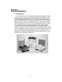
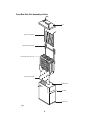
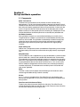
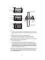
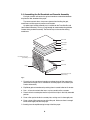
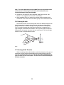
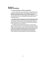
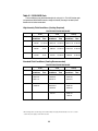
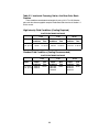
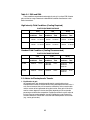
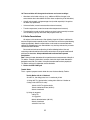
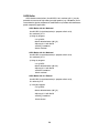
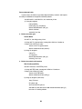
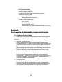
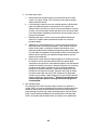
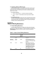
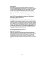
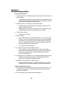
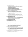
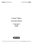
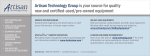
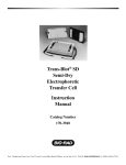
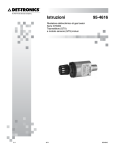
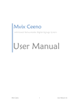
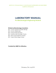
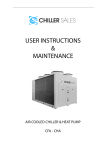
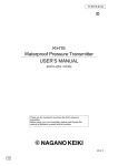
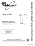
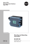
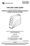
Trans-Blot® Plus
Electrophoretic
Transfer Cell
Instruction Manual
Catalog Number
170-3990
For Technical Service Call Your Local Bio-Rad Office or in the U.S. Call 1-800-4BIORAD (1-800-424-6723)
Table of Contents
Page
Section 1
General Information .........................................................................1
1.1
1.2
1.3
Introduction....................................................................................................1
Specifications ................................................................................................2
Safety.............................................................................................................3
Section 2
Set Up and Basic Operation of the Trans-Blot Plus Cell .............5
2.1
2.2
2.3
2.4
2.5
2.6
2.7
Components ..................................................................................................5
Additional Components .................................................................................6
Setting up the Tank and Cooling System .....................................................6
Assembling the Gel Sandwich and Cassette................................................8
Transfer .........................................................................................................9
Draining the Tank ........................................................................................10
Running Acidic Transfers ............................................................................10
Section 3
Transfer Conditions .......................................................................11
3.1
3.2
3.3
General Guidelines and Running Conditions .............................................11
Notes on Electrophoretic Transfer Conditions ............................................15
Buffer Formulations .....................................................................................17
Section 4
Strategies for Optimizing Electrophoretic Transfer ...................21
4.1
4.2
Optimizing Protein Transfer ........................................................................21
Optmizing DNA and RNA Transfer .............................................................23
Section 5
Choice of Blotting Membranes.....................................................23
5.1
5.2
Protein Blotting Membranes........................................................................23
DNA and RNA Blotting Membranes............................................................24
Section 6
Troubleshooting .............................................................................25
Section 7
Maintenance....................................................................................28
Section 8
Product Information .......................................................................29
Section 9
References ......................................................................................30
Section 10 Warranty ..........................................................................................31
Copyright© (2002) Bio-Rad Laboratories, Inc. All rights reserved.
Section 1
General Information
1.1 Introduction
The Trans-Blot Plus cell is an electrophoretic transfer cell designed for use with
large format gels, such as those used with the PROTEAN Plus Dodeca cell, and
for high-throughput blotting applications with smaller format gels, such as those
used with the Criterion Dodeca cell. The Trans-Blot Plus cell is supplied with three
gel holder cassettes, each with an effective blotting area of 26.5 x 28 cm. A pair of
plate electrodes- a platinum-coated titanium anode and a stainless steel cathodemay be positioned 4 cm, 7 cm, or 10 cm apart for electrophoretic transfers of one,
two, and three gel-containing cassettes, respectively. This variable placement
ensures a minimum distance between electrodes, which increases the field
strength and efficiency of transfer. Cooling, which is achieved with the Super cooling
coil and a refrigerated recirculating water bath, is required for high-intensity transfers
and is recommended for longer, overnight transfers. The Trans-Blot Plus tank is
designed to simultaneously accommodate the two plate electrode cards, three gel
holder cassettes and the Super cooling coil.
1
1.2 Specifications
Trans-Blot Plus cell tank
Overall dimensions
Material
Buffer requirement
Buffer capacity
39.4 cm x 17.27 cm x 30 cm
Acrylic
12 liters
14 liters
Electrodes
Electrode plate dimension
Electrode card dimension
Material
Support card
Anode plate
Cathode plate
Distance anode to cathode
22.86 cm x 24.45 cm
36.2 cm x 28.26 cm
Molded Polycarbonate
Platinum coated titanium
Stainless steel
Adjustable to 4 cm, 7 cm or 10 cm
Cassettes
Cassette dimension
Material
Blotting area
Gel capacity per cassette
28 x 30.7 cm
Molded Polyphthalamide (PPA)
26.5 x 28 cm
1 PROTEAN Plus, PROTEAN II XL, or
PROTEAN II xi gel; 4 Criterion gels or
9 ReadyGel gels
Gel/cassette assembly tray
Material
Overall dimensions
Molded PETG
42 x 42 x 6.3 cm
2
1.3 Safety
!
Power to the Trans-Blot Plus cell is supplied by an external DC voltage power
supply. This power supply must be ground isolated in such a way that the DC
voltage output floats with respect to ground. All of Bio-Rad’s power supplies meet
this important safety requirement. Regardless of which power supply is used, the
maximum specified operating parameters for the cell are:
!
300 VDC
Maximum voltage limit
300 Watts
Maximum power limit
40°C
Maximum ambient temperature limit
Current to the cell, provided from the external power supply, enters the unit
through the lid assembly, providing a safety interlock to the user. Current to the cell
is broken when the lid is removed. Do not attempt to circumvent this safety
interlock. Always turn the power supply off before removing the lid, or when working
with the cell in any way.
The Trans-Blot Plus is certified to meet EN61010-1* safety standard for safety
of laboratory equipment. Certified products are safe to use when operated in
accordance with the instruction manual. This safety certification does not extend to
other equipment or accessories not EN61010-1 certified, even when connected to
the Trans-Blot Plus.
This instrument should not be modified or altered in any way. Alteration of this
instrument will void the manufacturer’s warranty, void the EN61010-1 safety
certification and create a potential safety hazard for the user.
Bio-Rad is not responsible for any injury or damage caused by the use of this
instrument for purposes other than for which it is intended or by modifications of
the instrument not performed by Bio-Rad or an authorized agent.
*EN61010-1 is an internationally accepted electrical safety standard for laboratory instruments.
3
Trans-Blot Plus Cell Assembly of Parts
Lid
Super Cooling Coil
Cathode Plate (Black)
Gel Holder Cassettes (3)
Anode Plate (Red)
Buffer Tank
Tra
ns
-B
lo
tP
lus
Cel
l
Handles
Drain Port
Fig. 1.
4
Section 2
Set up and Basic operation
2.1 Components
Buffer Tank and Lid
The buffer tank and lid combine to fully enclose the inner chamber during
electrophoresis. The lid cannot be removed without disrupting the electrical circuit.
Handles on both sides of the tank facilitate transport. Guide marks on the front and
back of the tank identify appropriate fill levels for transfer buffer. On the inside, the
tank has 5 separate slots for variable placement of the electrode cards and gel
holder cassettes and a designated space for the cooling coil. Multiple ports on the
lid allow three different connection points for the cathode (black) electrode card.
Gel Holder Cassettes
Each gel holder cassette has an overall effective blotting area of 26.5 x 28 cm.
The gel/membrane sandwich is placed into the cassette between two fiber pads,
which are also included. The gel holder cassette design includes three separate
clamps that ensure even pressure across the gel and membrane sandwich. A
detachable hinge mechanism prevents gel sandwiches from slipping during
assembly.
Super Cooling Coil
Coolant from a refrigerated circulator (see Additional Components) passes through
the Super cooling coil to cool the transfer buffer during high intensity or prolonged
runs.
Electrode Cards
The Trans-Blot Plus cell is supplied with a pair of plate electrodes- a platinum-coated
titanium anode and a stainless steel cathode. Both electrode cards are removable.
The anode plate (red) must be placed into the slot that is nearest the front face of the
buffer tank. The placement of the cathode plate (black) is variable; the cathode plate
may be positioned in either the third, fourth or fifth slot (4 cm, 7 cm, or 10 cm away
from the anode) for electrophoretic transfers of one, two, and three gel-containing
cassettes, respectively. The electrode cards are held in place in the tank with the
nylon screws (provided).
Roller
The roller is used to ensure proper contact between gel and membrane and to
remove trapped bubbles during sandwich assembly.
Stir bar
A 3" x ½" stir bar is included with the Trans-Blot Plus cell and should be used
during every electrophoretic run to maintain uniform conductivity and temperature
during transfer.
Drain Port and Quick-Connect Fitting
The drain port and quick-connect fitting on the side of the Trans-Blot Plus cell
facilitate draining the buffer from the tank after transfer. Remove at least half of the
transfer buffer volume prior to moving the tank.
5
2.2 Additional Components
Magnetic stir plate
A magnetic stir plate with a surface area that is sufficient to accommodate the
Trans-Blot Plus cell is required for constant stirring of transfer buffer during
electrophoresis. Recommended stir plates include the PC-610 from Corning, the
Cimarec 3 from Thermolyne and the Vel A from Cole Parmer.
Refrigerated circulator
The Trans-Blot Plus cell requires a refrigerated circulator to work with the Super
cooling coil for optimal results. The recommended minimum cooling capacity of the
refrigerated circulator is 300W at 20°C and minimum pump flow rate is 4 L/min.
Recommended chillers include the Model RTE-7 from Thermo NESLAB and the
Model WKL 26 from Thermo Haake.
Tubing
Tubing with a 3/8 " internal diameter is required to connect both ends of the Super
cooling coil to the refrigerated circulator and for draining the tank using the
quick-release fitting and drain port.
Gel/ Cassette Assembly Tray
The optional gel/ cassette assembly tray is large enough to accommodate a gel
holder cassette and the buffer required for sandwich assembly and may be
purchased separately (see Product Information).
2.3 Setting up the tank and cooling system
1. Prepare the transfer buffer. See Section 3.3 for buffer formulations. Generally,
15 liters of transfer buffer will suffice for electrophoresis, gel equilibration, and
sandwich assembly.
2. Position the anode (red) electrode card into the tank, in the slot that is nearest
the front face of the tank (see Figures 1 and 2). This is the only position
possible for the anode plate since it is the only position that will provide a
connection between the plate electrode and the anode leads in the lid.
Tighten the electrode card in place with the white nylon screw.
3. Position the cathode (black) electrode card into the third, fourth or fifth slot from
the front (4 cm, 7 cm, or 10 cm away from the anode card), depending on
whether you will be transferring one, two, or three gel-containing cassettes,
respectively (see Figure 2). Tighten the electrode card in place with the white
nylon screw.
6
Super Cooling Coil
SLOT
5
4
Cathode Plate (Black)
3
Gel Holder Cassette (1)
2
Anode Plate (Red)
1
Cathode Plate (Black)
Super Cooling Coil
One Gel Holder Cassette Loaded
Super Cooling Coil
Cathode Plate (Black)
Gel Holder Cassettes (2)
Anode Plate (Red)
MAX LEVEL
MIN LEVEL
Two Gel Holder Cassettes Loaded
Trans-Blot Plus Cell
1 CASSETTE
Super Cooling Coil
Cathode Plate (Black)
Gel Holder Cassettes (2)
Anode Plate (Red)
Gel Holder Cassettes (3)
Anode Plate (Red)
Three Gel Holder Cassettes Loaded
Fig. 2.
4. If necessary, adjust the position of the cathode leads (black) on the lid so that
they correspond to the position of the cathode electrode plate (black) within the
tank.
5. Position the Trans-Blot Plus cell on a magnetic stir plate.
6. Add transfer buffer to the appropriate fill line. Choose the fill line that is
appropriate for the number of gel holder cassettes that you are using.
Note: In order to avoid overflow and electrical hazards, do not fill the tank beyond
the indicated buffer level lines marked on the tank.
7. Place the stir bar in the tank.
8. Start cooling. Cooling is required for high intensity field conditions and is
recommended for prolonged, unsupervised runs. Place the Super cooling coil
into its designated slot at the rear face of the tank. Connect the Super cooling
coil to the refrigerated circulator according to the manufacturer's instructions.
Avoid restrictive fittings, internal diameter reductions and excessive extensions
of tubing. Turn on power to the stir plate.
Note: To test that the cooling system is functioning properly before the first transfer
run is initiated, place the Trans-Blot Plus cell on the magnetic stirrer and pour in
11 L of buffer (or water). With no power applied to the tank, the buffer should cool
by 5°C in approximately 20 min.
7
2.4 Assembling the Gel Sandwich and Cassette Assembly
Each gel sandwich will contain the gel and membrane sandwiched between
two pieces of blot absorbent filter paper.
To prevent contamination, always wear gloves when handling the gels,
membranes and filter paper to prevent contamination.
An optional gel/ cassette assembly tray is available for the Trans-Blot Plus cell
(see Product Information). This tray is large enough to accommodate the gel holder
cassette during sandwich assembly. The lid of the tray can be used for soaking
membranes.
Fiber Pad
Filter Paper
Membrane
Gel
Filter Paper
Gel Holder Cassette
(Red Plate)
Clamp
Fiber Pad
Hinge
Gel Holder Cassette
(Black Plate)
Fig. 3.
1. For each gel, cut one piece of membrane and two pieces of filter paper to the
dimensions of the gel. Pre-cut membranes and filter papers are available (see
Product Information).
2. Equilibrate gels and membranes by soaking them in transfer buffer for 15 minutes.
3. Pour ~ 3 liters of transfer buffer into a tray for assembly of the cassettes.
4. Place the black cassette plate into the tray with the clamps in their fully extended
position.
5. Place a fiber pad on the black cassette plate, making sure it is thoroughly wet.
6. Place a piece of filter paper on top of the fiber pad. Make sure there is enough
buffer to thoroughly wet the filter paper.
7. Carefully place the equilibrated gel on top of the filter paper.
8
Note: Extra care is required when handling large gels, first align one side of the gel
with the side of the filter paper and slowly lower the rest of the gel.
8. Carefully place the pre-soaked membrane on top of the gel. Make sure the
membrane is properly positioned as it touches the gel. To avoid ghost prints or
artifacts, do not move the membrane after it is positioned. Use the roller to
remove any air bubbles and to ensure proper contact between the gel and
membrane.
9. Wet a second piece of filter paper in transfer buffer and place it on top of the
membrane.
10. Soak a fiber pad in transfer buffer and place it on top of the filter paper.
11. Place the hinge of the upper cassette plate (red) into the hinge mechanism of
the lower plate, and lower the upper cassette plate on top of the gel sandwich.
Make sure that the gel sandwich is aligned below the rim of the hinge so that
the cassette will close properly.
12. Working with one side at a time, apply firm pressure to the area adjacent to a
clamp and slide the clamp in.
13. Once the cassette is closed and locked, insert it into the tank with the hinge
side up. Make sure the red cassette plate faces the red electrode plate (see
Figure 4).
MAX LEVEL
MIN LEVEL
Trans-Blot Plus Cell
1 CASSETTE
2 CASSETTES
3 CASSETTES
Fig. 4.
2.5 Beginning Transfer
1. Once all the cassettes are in place, check that the buffer level is between the
maximum and minimum levels indicated on the tank.
2. Turn on the stir plate and check that the stirring and cooling are working properly.
3. Place the lid on the tank.
9
Note: The color-coded cables on the lid MUST attach to the electrode cards
of the same color. Reversing the orientation of the cables will cause
irreversible damage to the plate electrodes.
4. Connect the Trans-Blot Plus cell to the power supply. Begin the run. See
Section 3.1 for suggested run times with various buffers.
5. Upon completion of the run, remove the cassettes and disassemble the gel
sandwich on a flat surface so that one locking clamp can be released at a time.
2.6 Draining the tank
After transfer, remove at least half the buffer in the tank before moving the tank
off of the magnetic stir plate for cleaning. To drain the tank, use the drain port
fittings provided and an additional length of tubing (see Additional Components).
First, be sure that the open end of the tubing is placed into a receptacle that is
large enough to accommodate all the buffer. Then, insert the male quick-connect
fitting onto the drain port on the side of the tank (see Figure 5). The tank will begin
to drain as soon as the connection is made.
Fig. 5.
2.7 Running Acidic Transfers
When transferring under acidic conditions, switch the orientation of the gel and
membrane or simply reverse the orientation of the cassette so that the red side
faces the cathode electrode card (black). Do not reverse the electrode plates or
plug the cables into the reverse poles. This will cause irreversible damage to
the plate electrodes.
10
Section 3
Transfer Conditions
3.1 General Guidelines and Running Conditions
The electric field strength (V/cm) is the driving force in electrophoretic transfer.
Therefore, the most efficient transfers are obtained when the distance between the
electrodes of a blotting cell is reduced. The Trans-Blot Plus cell offers three
different electrode placements resulting in anode to cathode distances of 4, 7, and
10 cm for transfer of one, two, or three gel holder cassettes, respectively. In any of
these configurations, transfers may be performed under either high intensity or
standard field conditions.
High intensity field transfers require less than 5 hours to complete. Standard field
transfers require up to 16 hours to complete and are generally run overnight. In order
to produce such rapid transfers, high intensity transfers require higher power input
and consequently, produce more heat. Use of the Super cooling coil is required for
high intensity transfers and is recommended for standard field conditions, where the
run time is prolonged and usually unsupervised.
The following are recommended running conditions for a variety of transfer
buffers and electrode distances. Transfers may be performed under either constant
voltage or constant current settings. Constant voltage settings provide constant field
strength and tend to provide the most efficient transfer. Use of the Super cooling coil
should prevent heating when transferring under constant voltage. Please note that
the run times will need to be increased for gradient gels and may need to be
decreased if your proteins have a low molecular weight and transfer quickly.
Transfer conditions should be optimized for every individual application.
11
Table 3.1 SDS-PAGE Gels
These conditions were determined empirically using 12.5% Tris-HCl Criterion gels
and prestained SDS-PAGE molecular weight standards (Catalog # 161-0318). See
Section 3.3 for buffer formulations.
High Intensity Field Conditions (Cooling Required)
PLATE ELECTRODE DISTANCE
4 cm
7 cm
Buffer
Power
conditions
Run
Time
Towbin
60V/2A*
90V/3A
45 min
15–30 min
CAPS
41V/2A
60V/3A
15 min
15 min
66V/2A
100V/3A
30 min
15–30 min
25V/2A
35V/3A
15 min
15 min
40V/2A
55V/3A
30 min
15–30 min
Carbonate
Power
conditions
Run
Time
10 cm
Power
conditions
100V/2A
45 min
120V/2.4A 15–30 min
Run
Time
100V/1.5A
60 min
130V/~2.3A 15–30 min
95V/2A
30 min
120V/2.5A 15–30 min
55V/2A
80V/3A
30 min
15–30 min
Standard Field Conditions (Cooling Recommended)
PLATE ELECTRODE DISTANCE
4 cm
7 cm
10 cm
Buffer
Power
conditions
Run
Time
Power
conditions
Run
Time
Power
conditions
Run
Time
Towbin
10V/0.3A
20V/ 0.7A
30V/ 1.1A
16 Hrs.
10V/0.2A
20V/0.4A
30V/0.7 A
16 Hrs.
10V/0.15A
20V/0.3A
30V/0.5 A
16 Hrs.
CAPS
10V/ 0.35A
20V/0.8A
4 Hrs.
10V/0.2A
20V/0.55 A
30V/0.9A
4 Hrs.
10V/0.2A
20V/0.4A
30V/0.6A
4 Hrs.
10V/0.7A
4 Hrs
10V/0.4A
20V/1A
4 Hrs
10V/0.33A
20V/0.7A
30V/1A
4 Hrs
Carbonate
* When running under constant voltage, the PowerPac 200 power supply will automatically cross over to constant
current if the power supply's current limit is reached.
12
Table 3.2 Native Gels
These conditions were determined empirically using 12.5% Tris-HCl Criterion
gels and native horse myoglobin samples. See Section 3.3 for buffer formulations.
High Intensity Field Conditions (Cooling Required)
PLATE ELECTRODE DISTANCE
4 cm
Buffer
Towbin
(no methanol)
Power
conditions
Run
Time
50V/2A
80V/3A
45 min
15–30 min
7 cm
Power
conditions
10 cm
Run
Time
90V/2A
45 min
100V/2.2A 15–30 min
Power
conditions
Run
Time
100V/1.7A
60 min
130V/2.3A 15–30 min
Standard Field Conditions (Cooling Recommended)
PLATE ELECTRODE DISTANCE
4 cm
Buffer
Towbin
(no methanol)
7 cm
Power
conditions
Run
Time
Power
conditions
Run
Time
10V/0.3A
20V/0.7A
30V/1.1A
16 Hrs.
10V/0.2A
20V/0.4A
30V/0.7A
16 Hrs.
13
10 cm
Power
Run
conditions Time
10V/0.15A
20V/0.3A
30V/0.5A
16 Hrs.
Table 3.3 Isoelectric Focusing, Native, Acid Urea Gels, Basic
Proteins
These conditions were determined empirically using 12.5% Tris-HCl Criterion
gels and native horse myoglobin samples. Read about acidic transfers in Section 2.7
of this manual.
High Intensity Field Conditions (Cooling Required)
PLATE ELECTRODE DISTANCE
4 cm
Buffer
0.7% Acetic
acid , pH 2.8
7 cm
Power
conditions
Run
Time
Power
conditions
Run
Time
50V/2A
70V/3A
45 min
15–30 min
70V/2A
110V/3A
60 min
15–30 min
10 cm
Power
conditions
Run
Time
100V/1.9A
60 min
125V/2.4A 15–30 min
Standard Field Conditions (Cooling Recommended)
PLATE ELECTRODE DISTANCE
4 cm
Buffer
0.7% Acetic
acid , pH 2.8
7 cm
10 cm
Power
conditions
Run
Time
Power
conditions
Run
Time
Power
conditions
Run
Time
10V/0.4A
20V/0.8A
16 Hrs.
10V/0.25A
20V/0.55A
30V/0.8A
16 Hrs.
10V/0.15A
20V/0.35A
30V/0.55A
16 Hrs.
14
Table 3.4 DNA and RNA
These conditions were determined empirically using 5% uniform TBE Criterion
gels and the low range Fluorescein labeled DNA standards. See Section 3.3 for
buffer formulations.
High Intensity Field Conditions (Cooling Required)
PLATE ELECTRODE DISTANCE
4 cm
7 cm
10 cm
Buffer
Power
conditions
Run
Time
Power
conditions
Run
Time
Power
conditions
Run
Time
1X TBE
30V/2A
40V/3A
30 min
15–30 min
44V/2A
67V/3A
45 min
15–30 min
63V/2A
93V/3A
60 min
15–30 min
1X TAE
21V/2A
30V/3A
30 min
15–30 min
35V/2A
50V/3A
45 min
15–30 min
454V/2A
70V/3A
60 min
15–30 min
Standard Field Conditions (Cooling Recommended)
PLATE ELECTRODE DISTANCE
4 cm
7 cm
10 cm
Buffer
Power
conditions
Run
Time
Power
conditions
Run
Time
Power
conditions
Run
Time
1X TBE
10V/0.6A
16 Hrs.
10V/0.35A
20V/0.85A
16 Hrs.
10V/0.25A
20V/0.55A
30V/0.9A
16 Hrs.
1X TAE
10V/0.8A
16 Hrs.
10V/0.5A
16 Hrs.
10V/0.35A
20V/0.8A
16 Hrs.
3.2 Advice for Electrophoretic Transfer
1. Equilibration of gels
All electrophoresis gels should be equilibrated in transfer buffer prior to
electrophoretic transfer to remove contaminating electrophoresis buffer salts. If
salts are not removed, they will increase the conductivity of the transfer buffer
and the amount of heat generated during the transfer. Also, gels will shrink or
swell to various degrees in the transfer buffer depending on the acrylamide
percentage and the buffer composition. Equilibration allows the gel to adjust to
its final size prior to electrophoretic transfer. Equilibration is not necessary in
situations where the same buffer is used for both electrophoresis and transfer
(e.g., native gel transfers).
15
2. Current limits
The PowerPac 200 Power Supply is capable of a 200 Volt output. Unless a
current limit is set, uncontrolled conductivity changes may result in full power
being delivered to the Trans-Blot Plus cell. The transfer buffer may heat up
(further increasing conductivity), resulting in a potential safety hazard. Refer to
the PowerPac 200 Power Supply Instruction Manual for setting current limits
and run times.
3. Polarity of transfer
Do not reverse the polarity of the plate electrodes. This will result in corrosion
and rusting of the stainless steel cathode. If this should occur, the stainless
steel should be cleaned with a mild, non-abrasive cleanser to remove the rust.
4. Dissipating Heat
Electrophoretic transfer entails large power loads and consequently, heat
generation. The use of the Super cooling coil and a refrigerated circulating bath
is required for high intensity field transfers and is recommended for long,
unsupervised runs. Pre-chilling the buffer or the use of ice blocks are common
practices for heat dissipation in blotting, yet their application for the Trans-Blot
Plus cell should be limited to only runs lasting less than 1 hr and requiring less
than 150 Watts total power.
Placing the Trans-Blot Plus cell in the cold room is not an adequate means of
controlling transfer buffer temperature. The tank of the Trans-Blot Plus cell is
an effective thermal insulator, thus it limits the efficient dissipation of heat.
6. Using a stir bar during transfer
For all blotting applications, a stir bar must be placed inside the Trans-Blot Plus
cell, so that the transfer buffer is stirred during the course of the experiment.
This will help to maintain uniform conductivity and temperature during
electrophoretic transfer. Failure to properly control transfer buffer temperature
results in poor transfer of macromolecules and poses a potential safety hazard.
7. Transfer buffer pH
Do not adjust the pH of transfer buffers unless this is specifically indicated.
Adjusting the pH of transfer buffers, when not indicated, will result in increased
buffer conductivity, manifested by higher initial current output and decreased
resistance.
8. Transfer buffer recommendations
Use only high quality, analytical grade methanol. Contaminated methanol can
cause increased transfer buffer conductivity and poor transfer. Reusing the
transfer buffer is not advised, since the buffer will likely lose its ability to
maintain a stable pH during transfer. Diluting transfer buffers below their
recommended levels is also not advised, since this will decrease their buffering
capacity.
9. Voltage limits
Do not increase the voltage settings beyond those indicated in Tables 3.1–3.4
for overnight operation. Buffer conductivity must be close to the current listed
and a current limit should be set on the power supply. If overnight transfers at
low voltages are ineffective, and higher voltages are necessary, then decrease
the transfer time and use active cooling with the higher voltage settings. Failure
to decrease transfer time and use cooling may result in a safety hazard.
16
10. These variables will change total resistance and current readings:
•
Alterations to the buffer make-up, (e.g., addition of SDS or changes in ion
concentration due to the addition of acid or base to adjust the pH of the buffers)
•
Gel pH, ionic strength, and percentage of acrylamide, especially if the gel has
not been fully equilibrated
•
Volume of buffer (current increases when volume increases)
•
Transfer temperature (current increases when temperature increases)
•
Time during the transfer at which reading was taken (current normally increases
as the buffering capacity diminishes with progress of the run)
3.3 Buffer Formulations
All recipes in this section make 1 liter of buffer. A total of 15 liters is sufficient for
transfer and gel/cassette assembly for the Trans-Blot Plus cell. Scale up the following
recipes appropriately. Note that some buffers can be made as concentrated stock
solutions and diluted prior to use. Some buffers may also be purchased as pre-made
concentrated stock solutions.
Do not add acid or base to adjust the pH of the following buffers. Use only
analytical grade methanol because metallic contaminants in low-grade methanol will
plate onto the electrodes. Always add methanol or ethanol last to prevent
precipitation.
Note: Some pH meter electrodes will not provide correct measurements of the pH of
Tris buffers. If the pH of the buffer is incorrect, check that the pH meter electrode is
designed to work with Tris buffers. If the pH meter electrode functions properly for
Tris buffers and the pH is below 8.0, remake the buffer.
1. Buffers for SDS-PAGE gels
Towbin Buffer
This is a general purpose transfer buffer that was first described by Towbin8.
Towbin Buffer with 20 % Methanol
25 mM Tris, 192 mM glycine, 20% v/v methanol, pH 8.3
a) Using 10X Tris /glycine buffer (catalog #161-0734 for 1L bottles or
catalog # 161-0757 for 5L cube)
100 ml of 10X Tris /glycine buffer
700 ml of deionized water (dd H2O)
200 ml of methanol
b) Using dry reagents:
3.03 g Tris
14.4 g glycine
600 ml deionized water (dd H2O)
200 ml of methanol
add dd H2O to 1 liter
17
Towbin Buffer with 10 % Methanol
25 mM Tris, 192 mM glycine, 10% v/v methanol, pH 8.3
a) Using 10X Tris /glycine buffer (catalog #161-0734 for 1L bottles or
catalog # 161-0757 for 5L cube)
100 ml of 10X Tris /glycine buffer
800 ml of deionized water (dd H2O)
100 ml of methanol
b) Using dry reagents:
3.03 g Tris
14.4 g glycine
600 ml deionized water (dd H2O)
100 ml of methanol
add dd H2O to 1 liter
Towbin Buffer with 15 % Ethanol
25 mM Tris, 192 mM glycine, 15% v/v ethanol, pH 8.3
a) Using 10X Tris/ glycine buffer (catalog #161-0734 for 1L bottles or
catalog # 161-0757 for 5L cube)
100 ml of 10X Tris /glycine buffer
750 ml of deionized water (dd H2O)
150 ml of ethanol
b) Using dry reagents:
3.03 g Tris
14.4 g glycine
600 ml deionized water (dd H2O)
150 ml of ethanol
add dd H2O to 1 liter
18
CAPS Buffer
CAPS-based transfer buffers (10 mM CAPS, 10% methanol, pH 11) may be
preferable for transfers of high molecular weight proteins (e.g. >50 000 Da) and in
cases where the glycine component of Towbin buffer may interfere with downstream
protein sequencing applications.
CAPS Buffer with 20% Methanol
10 mM CAPS (3-(cyclohexylamino)-1-propane sulfonic acid),
20% methanol, pH 11
a) Using dry reagents:
2.21 g CAPS
600 ml deionized water (dd H2O)
Adjust to pH 11 with NaOH
add dd H2O to 800 ml
200 ml methanol
CAPS Buffer with 10% Methanol
10 mM CAPS (3-(cyclohexylamino)-1-propane sulfonic acid),
10% methanol, pH 11
a) Using dry reagents:
2.21 g CAPS
600 ml deionized water (dd H2O)
Adjust to pH 11 with NaOH
add dd H2O to 900 ml
100 ml methanol
CAPS Buffer with 15% Ethanol
10 mM CAPS (3-(cyclohexylamino)-1-propane sulfonic acid),
15% ethanol, pH 11
a) Using dry reagents:
2.21 g CAPS
600 ml deionized water (dd H2O)
Adjust to pH 11 with NaOH
add dd H2O to 850 ml
150 ml ethanol
19
Dunn carbonate buffer
In some cases, this buffer may produce higher efficiency transfers and improve
the ability of antibodies to recognize and bind to proteins.
10 mM NaHCO3, 3 mM Na2CO3, 20% methanol, pH 9.9
a) Using dry reagents:
0.84 g NaHCO3
0.318 g Na2CO3 (anhydrous)
500 ml deionized water (dd H2O)
200 ml methanol
add dd H2O to I liter
2. Buffers for native gels
Towbin Buffer
25 mM Tris, 192 mM glycine, pH 8.3
a) Using 10X Tris /glycine buffer (catalog #161-0734 for 1L bottles or
catalog # 161-0757 for 5L cube)
100 ml of 10X Tris /glycine buffer
900 ml of deionized water (dd H2O)
b) Using dry reagents:
3.03 g Tris
14.4 g glycine
600 ml deionized water (dd H2O)
add dd H2O to 1 liter
3. Buffers for nucleic acid transfers
TBE (Tris-Borate EDTA)
89 mM Tris borate, 2 mM EDTA pH 8.3
a) Using 10X TBE buffer (catalog #161-0733 for 1L bottles or
catalog # 161-0770 for 5L cube)
100 ml of 10X TBE buffer
900 ml of deionized water (dd H2O)
b) Using dry reagents (10X stock)
108 g Tris base
55 g boric acid
40 ml 0.5 M EDTA, pH 8.0
Add 100 ml of the 10X stock to 900 ml deionized water (dd H2O)
to make a 1X working solution.
20
TAE (Tris-Acetate EDTA)
40 mM Tris-Acetate 1 mM EDTA
a) Using 50X TAE buffer (catalog #161-0743 for 1L bottles or
catalog # 161-0773 for 5L cube)
20 ml of 50X TAE buffer
980 ml of deionized water (dd H2O
b) Using dry reagents (50X stock)
242 g Tris base
57.1 ml glacial acetic acid
100 ml 0.5 M EDTA, pH 8.0
Add 20 ml 50X stock to 980 ml deionized water (dd H2O) to make
a 1X working solution.
Section 4
Strategies for Optimizing ElectrophoreticTransfer
4.1 Optimizing Protein Transfer
Generally, quantitative elution of denatured high molecular weight proteins is
difficult. The following tactics, alone or in combination, will increase transfer
efficiency.
1. Improve gel- membrane contact.
Failure of molecules to bind efficiently to the membrane, caused by poor
gel-membrane contact, is often confused with inefficient elution of proteins from
the gel. Poor contact is usually due to excess moisture in the gel-membrane
interface. Use the roller to assure good contact between the gel and membrane.
Proper selection of filter paper thickness will also help assure good compression.
Equilibrate the gel and membrane in transfer buffer for at least 15 minutes prior
to transfer to prevent shrinking of either component during transfer, and to
eliminate reactants such as urea or SDS from the gel.
2. Increase transfer time.
An initial control should be performed to determine the time required for
complete transfer1,2. Times may vary from as little as 15–30 minutes to as long
as overnight. Remember all overnight applications should be performed at
10–30 Volts to minimize heating problems.
3. Increase the power.
Initial controls should be performed to evaluate the efficiency of increasing the
V/cm as well as its effects on the temperature of transfer. The temperature
increase may change buffer resistance and subsequent power delivered, as
well as the state of protein denaturation, thus affecting transfer efficiency.
21
4. Vary buffer type and pH.
a.
Reduce the buffer strength. Dilution of transfer buffer results in lower
current at any given voltage. This will allow the use of higher voltages
without excessive heating.
b.
b. Maximize the charge-to-mass ratio. Alcohols present in SDS transfer
buffer strip SDS from proteins. Basic proteins in Tris, glycine, and
methanol buffer at pH 8.3 may assume a state near isoelectric neutrality
and thus, may transfer poorly. Buffers with pH of 9.5 to 10.0 have shown
much better elution and binding characteristics for basic proteins such as
lysozyme and histones3.
c.
Different buffer types at similar V/cm may yield different efficiencies.
Generally Tris buffers allow more efficient transfer than acetate or
phosphate buffers.
d.
Addition of 0.1% SDS detergent to Tris, glycine, and methanol buffer has
been reported to increase transfer efficiency2. SDS, however, increases
relative current, power, and heating. Temperatures below 10°C may
precipitate the SDS so the starting buffer temperature will be higher. SDS
may also affect the antigenicity of some proteins. SDS will aid in eluting the
proteins from the gel, but it may reduce the binding efficiency of those
proteins to the membrane4.
e.
Alcohol in the transfer buffer has opposing effects on the efficacy of transfer. Alcohol in the transfer buffer removes SDS from protein-SDS
complexes and increases the affinity between proteins and nitrocellulose
membranes. Alcohol also causes a reduction in gel pore size, restricting
transfer of some proteins. Alcohol may also cause some proteins to
precipitate and transfer inefficiently. Proteins bind efficiently to PVDF
membrane in the absence of alcohol. Therefore, elimination of alcohol
from the transfer buffer and use of PVDF membrane for SDS-protein
transfers may constitute a logical strategy for analysis of high molecular
weight or difficult-to-transfer proteins5,6. Alcohol is not required in the
transfer buffer when proteins are being transferred from gels not
containing SDS.
5. Alter membrane type.
As mentioned in 4e, PVDF membrane allows transfer in the absence of
alcohol. PVDF can increase the binding of low molecular weight proteins that
sometimes blow through nitrocellulose when transfers are long enough or
intense enough to transfer high molecular weight proteins. Use Immun-Blot
PVDF if the blot will be developed with immunochemicals. Use Sequi-Blot
PVDF is the proteins will be sequenced or analyzed by mass spectrometry.
22
4.2 Optimizing DNA and RNA Transfer
Altering the gel percentage can solve problems with elution of nucleic acids. It
may be somewhat more difficult to quantitatively transfer large amounts of DNA
used in genomic blots. The following tactics should be considered for optimizing
elution in such transfers.
1. Alter the gel composition.
a.
Lower % total monomer or % crosslinker for polyacrylamide gels.
b.
Lower % agarose. This allows better elution of high molecular weight
DNA.
2. Alter the DNA denaturants.
It has been found that glyoxal denaturation allows more efficient elution of DNA
than NaOH. Boiling polyacrylamide gels to denature DNA has also been found
to give excellent results7. Base denaturation often causes polyacrylamide gels
to weaken and stick to blotting membranes.
Section 5
Choice of Blotting Membranes
5.1 Protein Blotting Membranes
A variety of blotting membranes are available, each with particular advantages
depending on the needs of the experiment. The physical properties and performance
characteristics of a membrane should be evaluated in selecting the appropriate
transfer conditions.
Table 5.1 Guide to Protein Blotting Membranes
Membrane
Pore Size
Binding
Capacity
(µg/cm2)
Nitrocellulose
0.45 µm
0.2 µm
80–100
General purpose protein blotting
membrane
Supported
Nitrocellulose
0.45 µm
0.2 µm
80–100
Pure nitrocellulose cast on an
inert synthetic support; increased
strength for easier handling and for
reprobing.
PVDF
0.2 µm
170–200
High mechanical strength and
chemical stability, used for protein
sequencing and western blotting;
low background to signal ration,
enhanced binding in the presence
of SDS. Must be wet in alcohol
before equilibration in buffer.
Nylon
0.2 µm
170
Recommended for nucleic acids
23
Notes
PVDF Membrane
Bio-Rad offers PVDF (Polyvinylidene difluoride) membranes that are ideal for
immunoassays of blotted proteins (Immun-Blot PVDF) or amino-terminal sequencing
and amino acid analysis (Sequi-Blot PVDF). PVDF retains proteins under extreme
conditions, such as exposure to organic solvents or acidic or basic conditions.
Greater protein binding capacity allows for better retention of easily transferred
proteins, while allowing more time or higher voltages to transfer difficult or larger
proteins. Greater protein retention during sequencing manipulations enhances the
likelihood of obtaining information from rare, low abundance proteins, by increased
initial coupling and more consistent yields. In addition, PVDF membrane exhibits
better binding efficiency of blotted material in the presence of SDS in the transfer
buffer. PVDF must first be wetted in 100% methanol but can then be used in a
transfer buffer that does not contain alcohol.
Nitrocellulose Membrane
Nitrocellulose membranes have been used extensively for protein binding and
detection2,6,8-10. Nonspecific protein binding sites are easily and rapidly blocked on
nitrocellulose, avoiding subsequent background problems. No pre-activation of the
membrane is required. With nitrocellulose, low molecular weight proteins (especially
those <20,000 Da) may be lost during post transfer washes, thus limiting detection
sensitivity11. Smaller pore size nitrocellulose membrane (0.2 µm), has been shown
to be effective in eliminating this loss12. Large proteins (those >100,000 Da) that
are denatured by SDS may transfer poorly to nitrocellulose if alcohol is added to the
transfer buffer. Alcohol in the transfer buffer increases binding of SDS-proteins to
nitrocellulose, but decreases pore sizes in the gel.
5.2 DNA and RNA Blotting Membrane
Zeta-Probe® Nylon Membrane
Zeta-Probe membrane is an ideal alternative to nitrocellulose for the analysis of
nucleic acids. The membranes bind nucleic acids in low ionic-strength buffers,
making electrophoretic transfer of nucleic acids from agarose and acrylamide gels
possible. Zeta-Probe membrane allows efficient binding of all sizes of single
stranded DNA and RNA in the presence of low ionic strength buffers13. Unlike
nitrocellulose, Zeta-Probe membranes can be hybridized as many as 20 consecutive
times.
24
Section 6
Troubleshooting Guide
Poor transfer of proteins
1. Transfer apparatus is assembled incorrectly and the proteins are moving in the
wrong direction.
•
The gel/membrane sandwich may be assembled in the wrong order or the
cassette may be inserted in the tank with the wrong orientation. Check the
polarity of the connections to the power supply.
2. Detection system is not working or is not sensitive enough.
•
Include proper positive and negative control antigen lanes to test for kit
sensitivity. Consult kit manual.
•
Stain the gel after transfer with a total protein stain, like Coomassie® Blue
or SYPRO Ruby, to make sure that proteins have left the gel.
3. Transfer time is too short.
•
Increase the transfer time.
4. Power is too low.
•
Always check the current at the beginning of the run. The current may be
too low for a particular voltage setting. If the buffer is prepared improperly,
the conductivity may be too low, and not enough power will be delivered
to the cell. See the power guidelines for specific applications in Section 3.
•
Prepare new buffer or increase the voltage.
•
Try the high intensity blotting option.
5. Charge-to-mass ratio is incorrect (native transfers).
•
Try a more basic or acidic transfer buffer to increase protein mobility.
Proteins near their isoelectric point will transfer poorly. (Buffer pH should
be 2 pH units higher or lower than the pI of the protein of interest for
optimal transfer efficiency.)
6. Power supply circuit is inoperative, or an inappropriate power supply was used.
•
Check the fuse. Be sure the voltage and current output of the power
supply match the needs of the blotting instrument.
7. Methanol in the transfer buffer is restricting elution.
•
Reduction of methanol results in increased transfer efficiency of proteins
from the gel, but it also diminishes binding to nitrocellulose membranes.
Protein is precipitating in the gel
1. Use SDS in the transfer buffer. SDS can increase transfer efficiency, but it can
also reduce binding efficiency to nitrocellulose and affect reactivity of some
proteins with antibodies.
2. Eliminate alcohol from the transfer buffer (see Section 4).
25
Swirls or missing bands; diffuse transfers
1. Poor contact between the membrane and the gel. Air bubbles or excess buffer
remain between the blot and gel.
•
Use the roller carefully to roll over the membrane in both directions until
air bubbles or excess buffer is removed from between gel and membrane,
and complete contact is established.
•
Use thicker filter paper in the gel/membrane sandwich.
•
Replace the fiber pads. Pads will compress and degrade with time, and
will not hold the membrane to the gel.
2. The membrane is not properly wet or has dried out.
•
White spots on nitrocellulose membrane indicate dry areas where
protein will not bind. If wetting does not occur immediately by immersion
of the sheet in transfer buffer, heat distilled water until just under the
boiling point, and soak the membrane until completely wet. Equilibrate in
transfer buffer until ready for use.
•
Because of the hydrophobic nature of PVDF, the membrane must be
prewet in methanol prior to equilibration in aqueous transfer buffer. Follow
the directions in the product insert.
3. The gel electrophoresis may be at fault.
•
Artifacts of electrophoresis may occur as a result of poor gel polymerization,
inappropriate running conditions, contaminated buffers, sample overload,
etc. Consult your electrophoresis manual for more details.
Gel cassette pattern transferred to blot
1. Contaminated or thin fiber pads are used.
•
Replace the fiber pads, or thoroughly clean the contaminated pads.
2. The transfer buffer is contaminated.
•
Make fresh solutions.
Poor binding to the membrane — Nitrocellulose
1. 20% methanol in the transfer buffer is generally optimal for protein binding.
•
Make sure the buffer contains the proper amount of methanol.
2. Proteins may be transferring through the nitrocellulose.
•
Use PVDF or 0.2µm nitrocellulose (smaller pore size). Decrease the voltage
if using the high intensity option.
•
Place an additional piece of nitrocellulose membrane in the gel sandwich
and analyze this added piece for evidence of proteins that may have
transferred completely through the first piece.
3. Proteins <15,000 Da may show diminished binding to 0.45 µm nitrocellulose, or
may be washed from the membrane during assays.
•
Use PVDF or nylon membrane, which have higher binding capacities.
26
•
Use Tween-20 detergent in the wash and antibody incubation steps.
Reduce or eliminate the more stringent washing conditions.
4. SDS in the transfer buffer will reduce binding efficiency of proteins.
•
Reduce or eliminate the SDS from the transfer buffer.
5. The membrane may not be completely wet.
•
White spots on the membrane indicate dry areas where protein will not
bind. If wetting does not occur immediately by immersion of the sheet in
transfer buffer, heat distilled water until just under the boiling point, and
soak the membrane until it is completely wet. Equilibrate in transfer buffer
until ready for use.
Poor Binding to the Membrane — PVDF
1. The membrane may not be completely wet.
•
Because of the hydrophobic nature of PVDF, the membrane must be
completely soaked in methanol prior to equilibration in aqueous transfer
buffer. Follow the directions in the product insert.
2. The membrane may have been allowed to dry during handling.
•
3.
A completely wet membrane has a gray, translucent appearance. White
spots will form on the surface of the membrane, indicating that it has been
allowed to dry. Since proteins will not bind to the dry spots, rewet the
membrane with methanol and re-equilibrate in transfer buffer.
Proteins may be transferring through the membrane.
•
Decrease the voltage if transferring under high intensity conditions.
•
Place an additional piece of PVDF membrane in the gel sandwich and
analyze this added piece for evidence of proteins that may have
transferred completely through the first piece.
4. SDS in the transfer buffer will reduce binding efficiency of proteins.
•
Reduce or eliminate the SDS from the transfer buffer.
Power conditions are too high
•
Always check the current at the beginning of the run. The current may be too
high for a particular voltage setting. If the buffer is prepared improperly, the
conductivity may be too high, resulting in excessive power delivered to the cell.
See the power guidelines for specific applications in Section 3.
Immune-Specific Detection
Overall high background, low signal, or lack of development of positive control.
•
Consult instructions for immune detection kit or reagents.
Total Protein Detection
Consult stain or detection kit user manual.
27
Section 7
Maintenance
Cleaning
•
After transfer, remove at least half the buffer remaining in the tank before
attempting to lift or move the tank from the magnetic stir plate for cleaning. See
Section 2.6 for instructions.
•
Use mild soap and warm water to clean the electrodes, cassettes and buffer
tank. Take special care when cleaning the electrode cards or plate electrodes.
Do not use abrasives or strong detergents. Avoid scratching or marring the
platinum plate. The cathode plate (stainless steel) can be cleaned with a mild
abrasive to remove salt that may be deposited during normal operation.
•
Rinse fiber pads thoroughly under hot water and then in distilled deionized
water. Improper cleaning of the fiber pads may lead to the appearance of
artifacts on subsequent blots.
Chemical compatibility
•
The Trans-Blot Plus cell components are not compatible with chlorinated
hydrocarbons (e.g., chloroform), aromatic hydrocarbons (e.g., toluene,
benzene), or acetone. Use of organic solvents voids all warranties.
28
Section 8
Product Information
Catalog
Number
Product description
170-3990
Trans-Blot Plus Cell with Plate Electrodes and Super Cooling
Coil, includes 3 gel holder cassettes, cell with lid and power cables,
6 fiber pads, 1 pack blot absorbent paper (26.5 x 28 cm; pack of 30),
roller and stir bar
165-5052
PowerPac 200 Power Supply, 110/120 V
165-5053
PowerPac 200 Power Supply, 220/240 V
Trans-Blot Plus Cell Accessories
170-3994
Trans-Blot Plus Gel/Cassette Assembly Tray
170-3995
Fiber Pads, 27 x 28.5 cm, 2
170-3996
Blot Absorbent Paper, 26.5 x 28 cm, 60 sheets
162-0251
Nitrocellulose Membrane, 0.45um, 26.5 x 28cm, 10 sheets
162-0252
Nitrocellulose Membrane, 0.2um, 26.5 x 28cm, 10 sheets
162-0253
Supported Nitrocellulose Membrane, 0.2um, 26.5 x 28cm,
10 sheets
162-0254
Supported Nitrocellulose Membrane, 0.45um, 26.5 x 28cm,
10 sheets
162-0255
Immun-Blot PVDF membrane, 26.5 x 28 cm, 10 sheet
162-0256
Sequi-Blot PVDF membrane, 26.5 x 28 cm, 10 sheets
170-3997
Stir bar
170-3998
Trans-Blot Plus Roller, 6 inch wide
170-3999
Trans-Blot Plus Gel Holder Cassette, 1
170-4990
Trans-Blot Plus Super Cooling Coil
170-4991
Trans-Blot Plus Platinum Anode Plate Electrode
170-4992
Trans-Blot Plus Stainless Steel Cathode Plate Electrode
170-4995
Trans-Blot Plus Cell Buffer Tank
170-4996
Trans-Blot Plus Cell Lid with Cables
170-4997
Trans-Blot Plus Gel Holder Cassette Clamps, 3
29
Section 9
References
1. Burnette, W. N., Anal. Biochem., 112, 195 (1981)
2. Erickson, P. G., Minier, L. N. and Lasher, P. S., J. Immun. Meth., 51, 241 (1982)
3. Szewcyzyk, B. and Kozloff, L. M., Anal. Biochem., 150, 403 (1985)
4. Perides, G., Plagens, U. and Traub, P., Anal. Biochem., 152, 94 (1986)
5. Gershoni, J. M. and Palade, G. E., Anal. Biochem., 124, 396 (1982)
6. Gershoni, J. M. and Palade, G. E., Anal. Biochem., 131, 1 (1983)
7. Peudelhuber, T. L., Ball, D. J., Davis, A. H. and Garrard, W. J., Nuc. Acids Res.,
10, 1311 (1982)
8. Towbin, H., Staehelin, T. and Gordon,J., Proc. Nat. Acad. Sci., 76, 4350 (1970)
9. Anderson, N. L., Nance, S. L., Pearson, T. W. and Anderson, N.G.,
Electrophoresis, 3, 135(1982)
10. Howe, J. G. and Hershey, J. W. B., J. Biol. Chem., 2566, 12836 (1981)
11. Lin, W. and Kasamatsu, H., Anal. Biochem., 128, 302 (1983)
12. Polvino, W. J., Saravis, C. A., Sampson, C. E. and Cook, R. B., Electrophoresis,
4, 368 (1983)
13. Bio-Rad Technical Bulletin 1110 “Zeta-Probe Blotting Membranes” (1982)
Coomassie is a trademark of ICI.
30
Section 10
Warranty
The Trans-Blot Plus cell electrophoretic transfer cell is warranted for one (1)
year against defects in materials and workmanship. If any defects occur during this
warranty period, Bio-Rad Laboratories will repair or replace the defective parts
without charge. The following defects, however, are specifically excluded:
1. Defects caused by improper operation.
2. Repair or modification done by anyone other than Bio-Rad Laboratories or an
authorized agent.
3. Use of spare parts supplied by anyone other than Bio-Rad Laboratories.
4. Damage caused by deliberate or accidental misuse.
5. Corrosion due to use of improper solvent or sample.
6. Use with chlorinated hydrocarbons (e.g., chloroform), aromatic hydrocarbons
(e.g., toluene, benzene), or acetone.
For any inquiry or request for repair service, contact Bio-Rad Laboratories after
confirming the model and serial number of your instrument.
Warranty Information
Model:
Serial Number:
Date of Delivery:
Warranty Period:
* EN61010 is an internationally accepted electrical safety standard for laboratory
instruments.
* When running under constant voltage, the PowerPac 200 power supply may automatically
cross over to constant current if the power supply’s current limit has been reached.
31
Bio-Rad
Laboratories, Inc.
Life Science
Group
Bulletin 0000
US/EG
Web site www.bio-rad.com Bio-Rad Laboratories Main Office
Also in: Australia Ph. 02 9914 2800, Fx. 02 9914 2889 Austria
Belgium Ph. 09-385 55 11, Fx. 09-385 65 54
China
Brazil Ph. 55 21 507 6191 Canada
Czech Republic Ph. (420) 2-4141 0532 Fx. (420) 2-4143 1642 Denmark
Finland
France
Ph. 089 318 84-177,
7 Fx. 089 318 84-123
Hong Kong Ph. 852-2789-3300, Fx. 852-2789-1257 India
Israel Ph. 03 951 4127, Fx. 03 951 4129
Japan Ph. 03-5811-6270, Fx. 03-5811-6272
Korea Ph. 82-2-3473-4460, Fx. 82-2-3472-7003 Latin America Ph. 305-894-5950, Fx. 305-894-5960 Mexico Ph. 52 5 534 2552 to 54, Fx. 52 5 524 5971
The Netherlands Ph. 0318-540666, Fx. 0318-542216 New Zealand Ph. 64-9-4152280, Fx. 64-9-443 3097 Norway Ph. 47-23-38-41-30, Fx. 47-23-38-41-39
Poland Ph. (48) 22-8126 672, Fx. (48) 22-8126 682 Portugal
Russia Ph. 7 095 721 1404, Fx. 7 095 721 1412
Singapore Ph. 65-2729877, Fx. 65-2734835 South Africa 00 27 11 4428508, Fx. 00 27 11 4428525 Spain Ph. 34 91 590 5200, Fx. 34 91 590 5211
Sweden Ph. 46 (0)8-55 51 27 00, Fx. 46 (0)8-55 51 27 80 Switzerland Ph. 061 717-9555, Fx. 061 717-9550 United Kingdom Ph. 0800-181134, Fx. 01442-259118
Rev A
00-000
0000
Sig 0402
4006224 Rev B