1
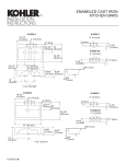
ALCOTT
FIRECLAY KITCHEN SINKS
K-6573-5U
12-1/2”
4” 4” 4” 4”
1-1/4” R.
K-6573-4
12-1/2”
4” 4” 4”
2”
4-1/4”
K-6573-3
2”
12-1/2”
4” 4”
2”
10”
22”
2-5/8”
1-7/8”
1” R.
25”
8-5/8”
(T)
25-1/8”
1-1/4”
1-1/2” OUTLET
.85<116
BEFORE YOU BEGIN
Please leave these instructions with the consumer as they
contain important care, cleaning, and maintenance
information.
SPECIFICATIONS
Fixture dimensions are nominal and conform to tolerances
by ASME Standard A112.19.9M.
Outlet . . . . . . . . . . . . . . . . . . . . . . . . . . . . . . . . . . . . 3-7/8” Dia.
Faucet holes, undercounter . . . . . . . . . . . . . . . . 2-1/2” Dia.
Faucet holes, tile-in . . . . . . . . . . . . . . . . . . . . . . . . 1-3/8” Dia.
(T) Drain typically = 14”.
BASIN SIZE
Side To Side
21”
Front To Back
15”
Depth
8”
NOTES
Please read these instructions before you begin.
CAUTION: Risk of poor installation. Proper selection
of tile is critical; Kohler recommends tile 3/8” thick.
113552-2-DA (B)
Because of the variance in tile thickness and other
properties, provide a sample of the tile to your carpenter,
tiler, plumber, and any other contractor involved in the
project. Because of the variety of tiles available, take careful
measurements prior to installation. It is very important that
all contractors discuss the requirements of the project with
each other.
Due to the variety of installations possible with these
sinks, installation may require procedures other than
those described in these instructions.
The cabinet and frame shown in these instructions are generic and may not represent actual design or structure.
Due to the special nature of this installation, Kohler Co.
recommends that an experienced cabinet maker build the
new cabinet or modify an existing cabinet for this sink.
To insure proper sink fit in the cabinet and support frame,
Kohler recommends providing the cabinet maker with the
actual sink to be installed.
Prior to installation, unpack new sink and carefully inspect
for damage.
To prevent damage, place the sink back into its original
packing carton until ready for installation.
All information in these instructions is based on the latest
product information available at the time of publication.
Kohler Co. reserves the right to make changes in product
characteristics, packaging, or availability at any time without notice.
1998 Kohler Co.
Dimension “H”
TOOLS & MATERIALS REQUIRED
Variable speed drill
Support frame members
1/2” dia. drill bit
Saber or keyhole saw
1-3/8” dia. hole saw
Ruler and pencil
Sanding block
Sealant (furnished)
Sandpaper (asst. grits)
Safety glasses
Orbital sander (optional)
New faucet (optional)
Cabinet Perimeter
Support
Max. Sink/Apron
Width
Wood Filler Strips/
Spacers
Fig. #2
2.
UNDERCOUNTER INSTALLATION
FAUCET CHECK
1. Check to see if the faucet can be completely assembled
See Fig. #3. Before proceeding, determine if the sink
will be flush with or extend slightly beyond the front of the
cabinet. The sink may extend beyond the face of the
cabinet 1-1/4” maximum.
Finished Wall
Cabinet
on the countertop being used. Measure the countertop
thickness and the available shank length between the
base of the faucet assembly and the mounting nut. If it
can, proceed with the installation. (If it cannot, select
another faucet or thinner countertop.) See Fig. #1.
ÉÉÉÉÉÉÉ
ÉÉÉÉÉÉÉ
Faucet Assembly
1-1/4”
MAX.
Countertop
Thickness
Fig. #1
3.
Mounting Nut
CABINET/SUPPORT FRAME
CONSTRUCTION
See Fig. #2. Measure the actual size of the kitchen sink,
including apron (bottom of the apron is approximately
1/8” wider than the top). The cabinet opening should
equal the maximum sink/apron dimensions to ensure a
minimum gap between the sink apron and the cabinet.
Reference the chart in Fig. #2 to determine the cabinet
opening height. The sink dimensions shown on the
cover of these instructions are for reference only.
NOTE: If sink is not available at time of installation, make
allowances to add wood filler strips/spacers to the cabinet
opening after cabinet is installed and before sink is installed.
DIMENSION “H”
Undercounter
Max. Apron Height
Tile-in
Maximum Apron Height Less Underlayment and Tile Thickness
Solid Surface
Max. Apron Height
Sink Outline
See Fig. #4. Construct a wood support and frame to fit
inside the cabinet opening. Allow adequate clearance
for water supply lines between support and finished
wall. Locate and cut out drain outlet clearance hole in
support. Location of this hole depends upon sink location determined in Step 2.
CAUTION: Risk of personal injury or product damage. The wood support and frame for the sink must sufficiently support 300 pounds (approximate weight of the
fireclay sink when full and a garbage disposal installed).
1.
INSTALLATION
TYPE
TOP VIEW
Fig. #3
Frame Members
Running Frontto-Back (Typical)
Water Supply
Lines
17” (Support
and Frame)
Sealant
Support (25 x 17”
Nom., must clear
water supply
lines)
Drain Hole Clearance (Hole
Dia. Must Clear Garbage
Disposal Mounting System)
Fig. #4
2
cess in case the sink needs to be removed or replaced.
Ensure that support/frame installation hardware will not
penetrate outside of cabinet.
TILE-IN SINK
3.
See Fig. #6. Install underlayment. Underlayment cutout may be slightly smaller than sink opening, but must
not support sink.
TILE-IN SINK INSTALLATION
4. Measure sink apron and cabinet opening to make sure
sink apron will fit into cabinet opening. If necessary,
sand opening or add wood filler strips.
6.
See Fig. #4. Place a thin layer of sealant (provided) at
each corner of the support where it will contact the sink.
Gently position sink within the frame, locating sink in
center of sink cabinet.
NOTE: Apply additional sealant if using shims.
Fig. #5
SUPPORT/FRAME INSTALLATION
CAUTION: Risk of product damage. Tile backer
board placed over plywood is the recommended underlayment for installing this sink. Tile should be bonded to
the backer board with dry set or Latex Portland mortar.
Consult the tile contractor to determine the types of material
to be used.
Acceptable underlayments include the following:
Tile backer board over 3/4” exterior grade plywood
3/4” exterior grade plywood
Do not use the following materials:
Flakeboard
Interior grade plywood
Gypsum wallboard
8.
Assemble strainer or garbage disposal to sink according
to manufacturer’s instructions.
9.
Placing sealant between apron and cabinet is optional.
UNDERCOUNTER SINK
See Fig. #6. The rim thickness on the sink is 5/8” plus or
minus 1/32”. The sink is designed for installation flush
with or slightly lower than the surrounding tile. Install
support/frame accordingly, or make allowance to shim
the sink as required by varying thickness of the tile, sink
height, and choice of adhesive or mortar bed installation.
Grout
ÉÉÉÉ
ÇÇÇ
ÉÉÉÉ
ÉÉÉÉ
ÉÉÉÉ
Sink
Tile
Undercounter
Fig. #7
Mortar or
Adhesive
SUPPORT/FRAME INSTALLATION
1. Position frame. Before securing frame, see preceding
Water Resistant Underlayment or
Backing Material 3/4” Minimum
1/4”
Optional
2.
Assemble faucet according to manufacturer’s instructions.
7.
Tile-in
1.
5.
support caution. Also, position frame installation hardware to allow for easy access in case the sink needs to
be removed or replaced. Ensure that frame installation
hardware will not penetrate outside of cabinet.
Cabinet Perimeter
Fig. #6
2.
Position support/frame as determined in Step 1. Before
securing, see support/frame caution. Also, position support/frame installation hardware to allow for easy ac-
3
Install support frame so that the top of sink rim (when
placed within the frame) is level and flush with top surface of cabinet perimeter support or underlayment at the
cut-out area. Secure frame to cabinet. See Fig. #8.
Sink
ÇÇ
ÇÇ
ÇÇ
ÇÇ
the sink is positioned to provide adequate clearance between faucet and backsplash, finished wall, or support
frame. This will ensure full faucet operation when installed.
Countertop
Sealant
Cabinet Perimeter
13. See Fig. #9. From back edge of countertop, locate the
dimension from finished wall to center of faucet holes
(Dim. “Y”) and draw the centerline. Add 1-1/2” to the faucet hole centerline to locate the back edge of the cut-out.
Trace the cut-out opening on the countertop using a soft
lead pencil. Locate the faucet holes.
Section View A-A
“Y”
1-3/8” D. Faucet Holes
4” 4”
Wood
Filler Strip
(Optional)
1-1/2”
Min.
“Y”
Cut-out
Fig. #8
22-3/4”
Min. Cut-out If Using
K-5984 Cutting Board
Fig. #9
sink apron will fit into cabinet opening. If necessary,
sand opening or add wood filler strips.
Assemble faucet according to manufacturer’s instructions.
5.
See Fig. #4. Place a thin layer of sealant (provided) at
each corner of the support where it will contact the sink.
6.
Gently position sink within the frame, locating sink in
center of sink cabinet.
ing the pencil line. Use an orbital sander or sanding
block to smooth the edge of the cut-out area and remove
all saw marks. For laminate-type countertops, all exposed unlaminated surfaces near the cut-out opening
must be adequately finished and sealed to prevent damage from water absorption.
See Fig. #8. Make sure the sink rim is level and flush
with the cabinet perimeter. Adjust or shim between sink
and support if needed to obtain proper fit. Top of sink rim
must be flush with top of cabinet perimeter in order to obtain proper contact with the underside of the countertop.
NOTE: Apply additional sealant if using shims.
Assemble strainer or garbage disposal to sink according
to manufacturer’s instructions.
9.
Using sealant between apron and cabinet is optional.
Sink
14. Cut out the opening in the countertop, carefully follow-
7.
8.
2” R. Max.
(Sharp Corner
Optional)
Countertop
UNDERCOUNTER SINK INSTALLATION
3. Measure sink apron and cabinet opening to make sure
4.
Finished
Wall
CAUTION: Risk of product damage. Do not cut, drill,
or sand countertop while positioned over fixture.
15. Drill required faucet hole locations (number of holes
drilled will be determined by the fitting being used) and
install faucet to countertop according to manufacturer’s
instructions. (Sink has five faucet holes.)
16. Clean the top of the sink rim, making sure surface is
free from debris. Clean the bottom of the countertop
around the cut-out area, making sure surface is smooth
and free of defects.
CUT-OUT POSITIONING
10. See Fig. #9. Due to the various cut-out sizes possible,
no template is supplied. If using the K-5984 cutting
board, the minimum cut-out length is 22-3/4”.
17. Apply a generous bead of sealant around the sink rim
11. Carefully measure the countertop to determine the ex-
18. Position the countertop over the sink, being careful the
(where sink rim and countertop meet).
sealant provides a complete seal between sink rim and
bottom of countertop. Immediately wipe away any excess sealant with a damp cloth. Fill any voids between
rim and countertop with provided sealant.
act location of the cut-out.
12. See Fig. #8. Measure the distance from finished wall to
the center of sink faucet holes (Dim. “Y”). This dimension will be used to locate the faucet hole centerline and
back edge of the cut-out on the countertop. Make sure
19. Sealing gap between apron and cabinet is optional.
4
cut-out. Trace the cut-out opening on the countertop
using a soft lead pencil. Locate the faucet holes.
SOLID SURFACE
INSTALLATION
6.
Cut out the opening in the countertop, carefully following
the pencil line. Use an orbital sander or sanding block to
smooth the edge of the cut-out area and remove all saw
marks. For laminate-type countertops, all exposed
unlaminated surfaces near the cut-out opening must be
adequately finished and sealed to prevent damage from
water absorption.
CAUTION: Risk of product damage. Do not cut, drill,
or sand countertop while positioned over fixture.
3 or 4 Faucet Holes
1-1/2” Min.
Solid Surface
Cut-out
“Y”
Finished Wall
2” R. Max.
(Sharp Corner
Optional)
Countertop
Fig. #10
NOTE: Do not use tile for this type of installation.
1.
Follow steps 1-8 as outlined in the undercounter sink
installation section.
22-3/4”
Min. Cut-out If Using
K-5984 Cutting Board
CUT-OUT POSITIONING
2. See Fig. #8. Due to the various cut-out sizes possible,
no template is supplied. If using the K-5984 cutting
board, the minimum cut-out length is 22-3/4”.
3.
4.
5.
Carefully measure the countertop to determine the exact location of the cut-out.
See Fig. #11. Measure the distance from finished wall to
the center of sink faucet holes (Dim. “Y”). This dimension will be used to locate the faucet hole centerline and
back edge of the cut-out on the countertop. Make sure
the sink is positioned to provide adequate clearance between faucet and backsplash, finished wall, or support
frame. This will ensure full faucet operation when installed.
Sink
Fig. #11
7.
Drill required faucet hole locations (number of holes
drilled will be determined by the fitting being used) and
install faucet to countertop according to manufacturer’s
instructions.
8.
Clean the top of the sink rim, making sure surface is free
from debris. Clean the bottom of the countertop around
the cut-out area, making sure surface is smooth and free
of defects.
9.
Apply a generous bead of sealant around the sink rim
(where sink rim and countertop meet).
10. Position the countertop over the sink, being careful the
sealant provides a complete seal between sink rim and
bottom of countertop. Immediately wipe away any excess sealant with a damp cloth. Fill any voids between
rim and countertop with provided sealant.
See Fig. #11. From back edge of countertop, locate the
dimension from finished wall to center of faucet holes
(Dim. “Y”) and draw the centerline. Subtract 1-1/2” from
the faucet hole centerline to locate the back edge of the
11. Sealing gap between apron and cabinet is optional.
5
IMPORTANT CONSUMER INFORMATION
LIMITED ONE-YEAR WARRANTY
CONSUMER RESPONSIBILITIES
Kohler plumbing fixtures and fittings are warranted free of
manufacturing defects.
A routine cleaning with a mild cleanser, especially if living in a
hard water area, will maintain the finish of this sink.
Kohler Co. will, at its election repair, replace, or make
appropriate adjustment where Kohler Co. inspection
disclosed any such defects occurring in normal usage within
two years after installation. Kohler Co. is not responsible for
installation costs.
Do not use abrasive cleaners or solvents.
To avoid potential damage to the finish, avoid soaking dishes
for a very long time and refrain from leaving coffee grounds
and tea bags in the sink.
To obtain warranty service, contact Kohler Co. either
through your Dealer or Plumbing Contractor or by writing
Kohler Co., Attn: Customer Service Department, 444
Highland Drive, Kohler, WI 53044 U.S.A., or by calling
1-800-4-KOHLER from within the U.S.A.
REQUESTING SERVICE
Please take a moment to familiarize yourself with the Kohler
Warranty, its benefits, and limitations. Kohler Co. and its
distributors support you with one of the largest Service
Networks of its type. Here’s what you need to do if you
require service:
First:
Implied warranties, including that of merchantability
and fitness for a particular purpose, are expressly
limited in duration to the duration of this warranty. To
the extent permitted by law, Kohler Co. disclaims all
implied warranties including merchantability and
fitness for a particular purpose. Kohler Co. disclaims
any liability for special, incidental, or consequential
damages.
Contact the dealer or contractor who sold and
installed the product. They should be able to
solve any problems you may have.
Second: If your dealer or contractor cannot solve the
problem, they will contact or supply you with the
name of the local Kohler Distributor and the:
Kohler Technical Specialist
THIRD:
Fourth:
Some states do not allow limitations on how long an implied
warranty lasts or the exclusion or limitation of incidental or
consequential damages, so this limitation and exclusion
may not apply to you. This warranty gives you specific legal
rights. You may also have rights which vary from state to
state.
If you are unable to obtain warranty service
through either your contractor or Kohler Co.
distributor, please write us directly at Kohler
Co., Attn: Customer Service Department,
444 Highland Drive, Kohler, WI 53044 U.S.A.
This is our exclusive written warranty.
Kohler Co., Kohler, Wisconsin 53044
Include all pertinent information regarding your
claim, including a complete description of the
product, model numbers, colors, finishes, and
the date the product was installed. Include a
description of the problem, and a photocopy of
your invoice for the products involved. Also give
us the name of the contractor and distributor.
6
7
8