1
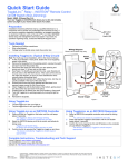
How to connect the ValveSentry to Insteon/Smarthome
Insteon® Leak Sensors
Model 2852-222
RF
Insteon®
Range
Extender
Model
2992-222
Power Line
SmartHome™
I/O Linc™
Sensor Model
#2450
ValveSentrytm
Se
ns
How it Works
The Insteon® Leak Sensors above senses a water leak and transmit a radio
frequence (RF) signal to the Insteon Range Extender. The Insteon Range Detector
repeats this water sense signal over the power line to the SmartHome™ I/O
Link™. The Insteon SmartHome Linc closes its relay which triggers the ValveSentry
using wires connected between the N/O and Com connections on the I/O Linc and
the Sensor connections on the ValveSentry.
Programming
1) The Insteon Leak detectors must be linked to the SmartHome I/O Linc.
2) There is no programing required for the Insteon Range Extender because it
simple mirrors the RF signal to the I/O Linc using the homes power lines.
3) It may be necessary to program the I/O Linc for optimum performance.
I.
Programming each Insteon Leak Detector
Referring to the Leak Sensor’s Owners Manual from Insteon, follow
the directions to “Make Leak Sensor a Controller”. You can repeat
these directions for each Leak Detector.
Note: Referring to the figure “Basic Insteon Link”. For the
configuration that you want, the Insteon leak detector is the
“Controller and the SmartHome I/O Linc is the Responder. Instruction
number 3 “Adjust the Responder to the desired brightness/state can
be confusing. The following explanation might help.
For this application, the desired brightness/state means the state of
the output relay on the I/O Linc. The state of the output relay on the
I/O Linc can be open or closed. The LED on the side of the I/O Linc is
dim when the relay is open and bright when the relay is closed. You
can change the state of the relay by a single push of the set button
which is next to the LED. You should try this out. Note that the
ValveSentry will turn the valve off when the relay is closed (LED is
bright). The ValveSentry will not open the valve when the relay is
placed back into the open state (LED is dim). You will need to push
the open button on the ValveSentry to open the valve. You can elect
to set up the system without it being connected to the ValveSentry to
minimize cycling a valve on and off. You do this by noting that a
bright LED means the relay is closed (and will close the valve) and a
dim LED means the LED is open.
Another important thing to be aware of is that the I/O Linc is factory
set in the latching mode (see below under programming the I/O linc).
This means that the relay will not reset itself automatically. The relay
toggles as described above. It is imperative that the relay be in the
latching state to program the Leak Detector. This is because you
need to place the relay in the closed state (LED bright) using the set
button to program the leak detector to close the relay when a leak is
present.
If for some reason the relay is not in the latching state, you can
program it to be in that state in two ways. Referring to the Insteon
I/O Linc Owners manual, either 1) using the instructions “Setting the
I/O Linc Output Relay Mode” or 2) “Resetting the I/O Linc to its
Factory Default Settings”
II.
Programming the SmartHome I/O Linc.
This can get a little more complicated. The I/O linc contains two main
functions. First it can be used to interface a sensor, which could be a
simple as a switch, to other devices such as the ValveSentry. For the
application we are working on there is no need to use the sensor
capabilities of the I/O Linc. However, you may think of creative ways
to use the capability. You will need to study the proper sections of
the Insteon I/O Linc’s Owner Manual to use this capability.
The I/O Linc can also be used to convert signals from the power line
to control other devices such as the ValveSentry. This is
accomplished by using the I/O Linc’s relay. This is the functionality
that is being used for this application.
The I/O Linc’s relay can be programmed to work in a number of ways.
See the section “Setting the I/O Linc Output Relay Mode” for
information regarding this.
The factory setting is in the latching mode. As stated before this
mode is required to link the Leak Detectors to the I/O Linc.
The I/O Linc will operate the ValveSentry in this mode. However, if
the ValveSentry is commanded to close the valve, you will need to
push the “Set” button on the I/O Linc to open the relay (LED turns
dim) before pushing the “Open” button on the ValveSentry to open
the valve. You can avoid the need to reset the I/O Linc’s relay to the
open state manually by setting the relay mode to Momentary A using
the instructions to do so “Setting the I/O Lync Output Relay Mode”.
The Momentary A position will close the relay for 2 sec, which should
be enough to trigger the ValveSentry, then reset the relay to the
open position. Two seconds should work fine but if it does not you
can set the relay close time to five seconds using the section “Setting
the I/O Link Momentary Duration” in the I/O Linc’s owners manual.
Expansion and Options
We tested the SmartHome system using two Leak Detectors, a single
Range Extender and an I/O Linc. Based upon our understanding of
the Insteon/SmartHome system there is no limit to the number of
Leak Detectors and Range Extenders. Thus the ValveSentry can be
used in many applications. You can also investigate one of
SmartHome hubs either as a substitution or in addition to the Range
Extender. We believe that this will allow you to get a notification or
monitor a leak indication. We at ValveSentry have not tested this so
consult the SmartHome people if you are interested.
Note: CustomControls the maker of the ValveSentry is not providing
any warrantees in regards to Insteon and or SmartHome products.
Our application of these products with the ValveSentry is only
meant to be helpful to our customers.