1
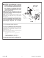
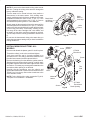
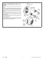
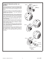
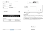
THERMOSTATIC MIXING VALVE TRIM
K-T9493, K-T9494
1. BEFORE YOU BEGIN
IMPORTANT INSTRUCTIONS
READ AND SAVE FOR THE CONSUMER
WARNING: Risk of scalding or other severe injury.
Before completing installation, the installer must set the maximum water temperature setting of this valve to
minimize the risks associated with scalding hazards according to ASTM F 444.
The installer is responsible for installing the valve and adjusting the maximum water temperature of this
thermostatic valve according to instructions.
This valve meets or exceeds ANSI A112.18.1M, ASSE 1016, and CSA B125.
If you do not understand any of the installation or temperature adjustment instructions in this document, in the United
States please contact our Customer Service Department at 1-800-4-KOHLER. Outside the U.S. please contact your
distributor.
IMPORTANT: Please fill in the blanks below and on the valve label. Then insert these instructions into the plastic
bag included with the valve package, and attach the plastic bag to the valve handle for the owner’s reference.
THIS DEVICE HAS BEEN PRESET BY ______________________ OF
_______________________ TO ENSURE A SAFE MAXIMUM TEMPERATURE.
ANY CHANGE IN THE SETTING MAY RAISE THE DISCHARGE TEMPERATURE
ABOVE THE LIMIT CONSIDERED SAFE, AND LEAD TO SCALDS.
DATE: _____________
CAUTION: Risk of scalding hazard. This device
has been calibrated at the factory to ensure a safe
maximum water temperature. Any variance in
settings or water inlet conditions from those used
during factory calibration may raise the discharge
temperature above the safe limit, and may present a
scalding hazard. Responsibility for installation and
adjustment of this device in accordance with these
instructions lies with the installer.
CAUTION: Risk of product damage. This valve
contains plastic and rubber components. Do not
apply excessive heat to the valve body when you
make solder connections. Do not apply flux or acids
directly to the valve, as damage to the seals, plastic
components, and trim finish may result. Do not apply
petroleum-based lubricants to the valve components,
as damage may result.
TOOLS AND MATERIALS REQUIRED
Thermometer
Thread sealant
3/4” nominal copper tubing and fittings
Solder and flux
Wrenches
Hacksaw or tubing cutter
Thin-blade knife or screwdriver
Silicone Sealant (optional)
116637-2-BC
ABOUT THIS VALVE
NOTES
The thermostatic mixing valve cartridge does not
contain an integral volume control/shut-off valve.
You must install a separate volume control/shut-off
valve (K-403) downstream of any valve outlet that
does not have an integral shut-off valve. The K-400
thermostatic mixing valve requires separate
volume control/shut-off valves downstream of
each mixing valve outlet. Refer to Fig. #3.
The K-401 thermostatic mixing valve contains a
single volume control/shut-off valve for controlling
the water flow through the shower outlet. When
plumbing to the valve’s bath outlet, you must install
a separate volume control shut-off valve (K-403)
downstream from the bath outlet. Refer to Fig. #3.
K-400 and K-401 thermostatic mixing valves do
not have an integral aspirator. For installations
that use a bath diverter spout, you must install a
twin ell (K-9663) with integral aspirator between
the valve and the bath spout. If these thermostatic
mixing valves are installed without an aspirator
water will flow from the shower and bath spout at
the same time. Refer to Fig. #3.
Determine the correct drain size and capacity for
your installation. If two thermostatic mixing valves
are used together, water flow volumes of 24 gpm
(1.51 lps) or more are possible, depending upon
the water supply pressure.
Determine the correct water heater size and
capacity for your installation. A typical shower
installation uses an approximate mix of 75% hot
water and 25% cold. A custom shower application
using three 2-1/2 gpm (.16 lps) showerheads can
use about 45 gal. (170.3 l) of hot water in 8 minutes.
Choose a water heater large enough for your
installation.
116637-2-BC
Shut off the main water supply.
Observe all local plumbing codes.
Inspect the waste and supply piping for damage.
Replace as necessary.
The valve is calibrated to 104 F (40 C) at the first
stop position, and the maximum temperature limit
stop is positioned so the outlet water temperature
does not exceed 120 F (49 C).
Factory calibrated inlet conditions are:
Hot and cold water pressure = 43-1/2 psi (3.05
kg/cm)
Hot water supply temperature = 149 F (65 C)
Cold water supply temperature = 59 F (15 C)
If inlet conditions differ from those used during
factory calibration, it may be necessary to
re-calibrate the valve after installation. The
installer must check the mixed flow
temperature after installation, and adjust the
valve as needed according to the instructions.
2
This valve complies with ASME A112.181M, ASSE
1016, and CSA B125. The valve is listed with
ASSE, CSA, and IAPMO/UPC.
Kohler Co., Kohler, WI U.S.A.
ROUGHING-IN – K-400-K WITH K-T9494-7
6-1/8” D.
(15.6cm)
3-1/16”
(7.8cm)
1-9/16”
(4cm)
MIN.
2-1/4”
(5.7cm) MAX.
4-13/16”
(12.2cm)
Fig. #1
ROUGHING-IN – K-401-K WITH K-T9493-4 OR K-T9493-7
TRIM
2-3/16”
(5.6cm)
2-1/8”
3-1/8”
(7.9cm)
7-1/2”
(19.1cm) D.
LEVER
2-3/16”
(5.6cm)
1-7/8” D.
1-9/16”
(4cm) MIN.
2-1/4”
(5.7cm) MAX.
4-13/16”
(12.2cm)
Kohler Co., Kohler, WI U.S.A.
3-3/4”
(9.5cm)
ROUND
Fig. #2
3
116637-2-BC
2. COMPOSITE LAYOUT
K.
F.
I.
E.
H.
J.
B.
B.
A. K-400 Thermostatic Mixer and
K-T9494 Trim
B. K-403 Volume Control and
K-T9472 Trim
To
Showerhead
A.
From VolumeControlled Supply
B.
C. K-9663 Twin Ell (For use with Bath
Diverter Spout)
D. Bath Spout with Diverter
E. Fixed Showerhead or Handshower
F.
K-9660 Vacuum Breaker (for use
with Handshower)
G. Bath Spout
H. K-405 3-Way Transfer Valve and
K-T9474 Trim
I. Pressure Loop with Bodysprays
J. K-401 Thermostatic Mixer with
Volume Control and K-T9493 Trim
C.
D.
K. Showerhead
G.
116637-2-BC
Fig. #3
4
Kohler Co., Kohler, WI U.S.A.
3. INSTALLATION
CONSTRUCT FRAMING AND INSTALL
ROUGH PLUMBING
Determine the desired location for the valve according to
the rough-in information on Page 3, and construct
suitable stud and support framing.
Use 3/4” nominal copper tubing and fittings throughout
this installation. Smaller diameter piping upstream or
downstream of the valve will reduce the performance of
the valve.
INSTALL VALVE
Cold Water
Supply Line
Flush the hot and cold water supply lines to remove any
debris.
CAUTION: Risk of product damage. This valve
contains plastic and rubber components. Do not
apply excessive heat to the valve body when you
make solder connections. Do not apply flux or acids
directly to the valve, as damage to the seals and
plastic components may result. Do not apply
petroleum-based lubricants to the valve components,
as damage may result.
Hot Water
Supply Line
Use thread sealant, and connect the 3/4” hot and cold water supply lines to the valve inlet ports. Install water hammer arrestors in the supply lines. The inlet ports are
marked “HOT” and “COLD”, and must be connected to
the correct water supply lines to ensure proper valve function. Make sure the integral volume control/shut-off valve
on the K-401 is on top.
Connect the water outlet lines to the valve ports. Use a
3/4” plug for any unused outlet port.
K-401
Hot Water
Supply Line
Cold Water
Supply Line
K-400
Fig. #4
The plaster guard is attached to the face of the mixing
valve with two screws. Do not remove the plaster guard
until instructed. Use the plaster guard to determine the
depth of the valve in the wall, and to trace the cut-out line
in the wall material. The finished wall surface must be
within the MIN. – MAX. depth shown on the plaster guard.
Secure the water supply piping to the support framing.
Finished Wall
Plaster
Guard
11/16”
(1.7cm)
1-9/16” – 2-1/4”
(4cm – 5.7cm)
Fig. #5
Kohler Co., Kohler, WI U.S.A.
5
116637-2-BC
CAUTION: Risk of scalding hazard. Do not turn the
thermostatic mixing valve stem after you adjust the
temperature setting until you install the mixing handle
trim. This device has been calibrated at the factory to
ensure a safe maximum water temperature. Any
variance in settings or water inlet conditions from
those used during factory calibration may raise the
discharge temperature above the safe limit, and may
present a scalding hazard.
Volume Control/
Shut-off Valve
Cold Water
Supply Line
K-400: Turn on the water supply lines to the valve, and
check for leaks. Run water through the mixing valve and
all showers and the spout, and check the system for
leakage. Turn off the water.
K-401: Remove the plaster guard. Do not turn the
thermostatic mixing valve stem until you have installed
the handle trim.
Turn on the water supply lines to the valve, and check for
leaks. Run water through the mixing valve and all showers
and the spout, and check the system for leakage. Use the
volume control/shut-off valve (top control) to control the
water flow to the shower outlet. Turn off the water.
Reinstall the plaster guard.
Complete the finished wall.
Mixing
Valve Stem
Hot Water
Supply Line
Fig. #6
ADJUST TEMPERATURE SETTINGS
This valve has been calibrated at the factory to provide
104 F (40 C) water at the mixing valve’s first stop
position. The maximum temperature limit stop has been
adjusted so the maximum water temperature will not
exceed 120 F (49 C).
NOTE: The listed water temperature settings are based
upon the following factory conditions:
Hot and cold water pressure = 43.5 psi (3.05
kg/cm)
Hot water temperature = 149 F (65 C)
Cold water temperature = 59 F (15 C)
If the actual water supply conditions differ significantly
from those listed, you may need to re-calibrate the valve.
116637-2-BC
6
Kohler Co., Kohler, WI U.S.A.
NOTE: Do not turn the thermostatic mixing valve stem at
this time. Turning the mixing valve stem will change the
factory calibration setting.
Turn the water on for several minutes, then position a
thermometer in the water stream. If the existing water
supply conditions match the factory conditions, the water
temperature should be close to 104 F (40 C). If the
water temperature is not close to 104 F (40 C), remove
and discard the plaster guard if it is still attached.
Slowly rotate the thermostatic mixing valve stem until the
water temperature is a constant 104 F (40 C). The white
mark on the limit stop should be in line with the black mark
on the mixing valve body. If necessary, carefully pry the
limit stop off the valve cartridge with a thin blade, and
re-install it so the white mark faces upward as required.
The limit stop must be correctly positioned to ensure trim
fit.
Do not turn the thermostatic mixing valve stem after you
adjust the temperature setting until you have installed the
mixing handle trim.
White
Mark on
Limit Stop
Black Mark
on Mixing
Valve Body
Valve
Stem
Fig. #7
INSTALL MIXING VALVE TRIM – ALL
MODELS
Valve
Collar
Remove and discard the plaster guard if it is still in place.
Thread the collar(s) to the valve, and hand tighten.
Verify that each trim seal is correctly installed in an
escutcheon hole. The seal(s) should be installed so the
flat side faces outward, and the tapered side in.
Remove the backing from the adhesive gasket material.
Starting at the escutcheon drain opening, carefully apply
the gasket material around the back edge surface of the
escutcheon. Trim away any excess gasket material so the
escutcheon drain opening is not blocked.
Carefully slip the escutcheon over the collar(s) and
against the finished wall. Position the escutcheon so the
“Kohler” logo is to the top. Secure the escutcheon to the
valve with two screws.
NOTE: For the K-400 mixing valve, proceed to Fig. #10,
“Complete Trim Installation – All Models” .
Limit Stop
Adhesive
Gasket
K-T9493
Escutcheon
Finished
Wall
Collar
Screw
Collar
Trim
Seal
Valve
Adhesive
Gasket
K-T9494
Escutcheon
Drain Opening
Screw
Fig. #8
Kohler Co., Kohler, WI U.S.A.
7
116637-2-BC
INSTALL VOLUME CONTROL TRIM – K-401
VALVE
Rotate
Counterclockwise
Rotate the volume control valve stem fully counterclockwise.
Press the volume control knob onto the volume control
valve stem so the “Off” indicator graphic (smallest line) is
to the top (toward the top escutcheon detent), as shown.
Secure the volume control knob to the valve stem with the
screw.
For Round Handle: Carefully install the thin O-ring into
the first groove in the volume control knob. Fit the
uninstalled grip ring into the second groove in the volume
control knob.
For Lever Handle: Install the O-ring into the groove in the
volume control knob.
For All Handles: Press the cap onto the volume control
knob so the cap detent is in line with the “High” indicator
graphic on the volume control knob.
Lever Handle
Volume Control
Knob
O-Ring
Round Handle
Volume Control
Knob
Cap
Screw
O-Ring
Detent
“Off”
Indicator
Graphic
“High”
Indicator
Graphic
116637-2-BC
Screw
8
Grip
Ring
Fig. #9
Kohler Co., Kohler, WI U.S.A.
COMPLETE TRIM INSTALLATION – ALL
MODELS
Detent
Press the mixing valve knob onto the mixing valve stem
so the knob button and “104” mark face upward (toward
the escutcheon detent), as shown. Verify that the knob
does not rotate counterclockwise. Do not press the knob
button.
Turn on the water for a few minutes to allow the
temperature to moderate. Then use a thermometer to
check the water temperature. The water temperature
should be 104 F (40 C).
If the water temperature is 104 F (40 C), press the knob
button and rotate the knob fully counterclockwise so the
“120” mark faces upward. Check the water temperature
again. It should now be 120 F (49 C). Turn the knob
clockwise so the “104” mark is upward. Again check the
water temperature to make sure it is still 104 F (40 C).
Turn off the water.
If the water temperature does not match the temperature
indicated on the knob, repeat the mixing valve calibration
steps according to the “Adjust Temperature Settings”
section starting on Page 6.
Secure the mixing valve knob to the valve stem with the
screw. Install the thin O-ring into the first groove in the
knob. Carefully position the uninstalled grip ring into the
second groove in the knob.
Press the cap onto the valve so the cap detent is in line
with the knob button. If needed, apply a small amount of
the supplied silicone lubricant (capsule included in
hardware kit) to the inside wall of the cap to aid in
assembly.
Mixing Valve
Stem
Mixing
Valve Knob
Detent
Detent
Screw
Grip Ring
Detent
O-Ring
Silicone Lubricant
(if needed)
Cap
Fig. #10
Kohler Co., Kohler, WI U.S.A.
9
116637-2-BC
116637-2-BC
10
Kohler Co., Kohler, WI U.S.A.
Kohler Co., Kohler, WI U.S.A.
11
116637-2-BC
In the U.S.A., call 1-800-4-KOHLER
In Mexico, call 001-877-680-1310
In Canada, call 1-800-964-5590
116637-2-BC
116637-2-
2001
12Kohler Co
Kohler Co., Kohler, WI U.S.A.