1
#LT12 - 11/11
I.
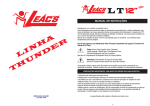
Anchoring Template
on Bottom of Box
•
•
Drilling guides for CEILING MOUNT Installation
Drilling guides for WALL MOUNT installation
CONVERTING MAKESHIFT METHODS INTO ENGINEERED SOLUTIONS'"
QUICK STANDTM
Model#
Description
SUSPENDED EQUIPMENT PLATFORM
40-SWHP-A
CEILING ONLY. NO CROSS BRACES. Suspended Platform supports water heaters up to
20 gallons or 375 pounds. 21-114" x 21-1/4" Pan. 1" PVC DRAIN FITTING.
50-SWHP-A
CEILING ONLY. NO CROSS BRACES. Suspended Platform supports water heaters up to
50 gallons or 600 pounds. 26-1/2" x 26-1/2" Pan. 1" PVC DRAIN FITTING.
40-SWHP
CEILING ONLY. CROSS BRACES. Suspended Platform supports water heaters up to
20 gallons or 375 pounds. 21-1/4" x 21-1/4" Pan. 1" PVC DRAIN FITTING.
50-SWHP
CEILING ONLY. CROSS BRACES. Suspended Platform supports water heaters up to
50 gallons or 600 pounds. 26-1/2" x 26-1/2" Pan. 1" PVC DRAIN FITTING.
40-SWHP-M
CEILING ONLY. NO CROSS BRACES. Suspended Platform supports water heaters up to
20 gallons or 375 pounds. 21-1/4" x 21-1/4" Pan. 1" WELDED STEEL DRAIN FITTING.
50-SWHP-M
CEILING ONLY. NO CROSS BRACES. Suspended Platform supports water heaters up to
50 gallons or 600 pounds. 26-1/2" x 26-1/2" Pan. 1" WELDED STEEL DRAIN FITTING.
40-SWHP-W
WALL HUNG OR CEILING. Suspended Platform supports water heaters up to 20 gallons
or 375 pounds. 21-1/4" x 21-1/4" Pan. 1" PVC DRAIN FITTING.
50-SWHP-W
WALL HUNG OR CEILING. Suspended Platform supports water heaters up to 50 gallons
or 600 pounds. 26-1/2" x 26-1/2" Pan. 1" PVC DRAIN FITTING.
40-SWHP-WM WALL HUNG OR CEILING. Suspended Platform supports water heaters up to 20 gallons
or 375 pounds. 21-1/4" x 21-1/4" Pan. 1" WELDED STEEL DRAIN FITTING.
50-SWHP-WM WALL HUNG OR CEILING. Suspended Platform supports water heaters up to 50 gallons
or 600 pounds. 26-1/2" x 26-1/2" Pan. 1" WELDED STEEL DRAIN FITTING.
Installation instructions located inside of box
For more information, contact us at::
(800) 321-0316
-.lholdrite.com
••
Orientation for Wall Mounting -
t Up
••
Box Template
(Not to Scale)
SAFETY FIRST! Always make sure that electrical wiring, water
pipes or other utilities inside the wall or ceiling will not interfere
with mounting this equipment! Appropriate personal protective
equipment, such as safety glasses, hearing protection and
gloves, are recommended.
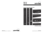
INSTALLATION MATERIALS
II.
PART DESCRIPTIONS
-Included & Not Included
(See Below for Quantities)
~Style
u,;...,..
""'"""'
for 1-5/8" Strut Channel
Screw, Hex Head, #3/8-16 X 1-1/2''
Hot Dipped Galvanized or Zinc Plated
Unistrut #P1047 Or Equal.
Unistrut® "Strut Channel Stud" for
1 5/8" Strut Channel Or Equal
Unistrut #P2380-4, 3/8-16 X 1-3/8"
@
TOGGLER®
Toggle Bolt
#3/8-16
Lag Bolt, Hex Head, #3/8 X 2-1/2"
Hot Dipped Galvanized or Zinc Plated
Unistrut® #P1000 I #P1100 {or equal)
1-5/8" X 1-5/8" X 36" minimum length
12 or 14-Gage Galvanized Steel Strut
~®
~CD
Bracket for attaching all-thread
rod to wall and platform
Unistrut® "Suspension Washer"
GripStyle for 1-5/8" Strut Channel
Unistrut #P2862, #3/8-16 or Equal
~©
Hex Nut, 3/8" or 1/2" Hot Dipped
Galvanized or Zinc Plated
{to match size of item R below)
Washer, Flat, 3/8" or 1/2"
Hot Dipped Galvanized
or Zinc Plated
Carriage Bolt, #3/8 X 2-1/2"
Hot Dipped Galvanized or Zinc Plated
@
3/8" or 1/2" all-thread rod
{length based on overhead
installation elevation)
~CL
~Cross
braces on
certain SWHP models
{for seismic zones)
CEILING MOUNT
WALL MOUNT - CONCRETE
#40-SWHP-W, #40-SWHP-WM, #50-SWHP-W, #50-SWHP-WM
•
Part#
1
'S'
1
1
'P' (-M models include welded steel drain body}
'T' (Certain SWHP models)
Parts Supplied by Installer
Qty,
Part #
~
Ea.r1.it
4
Pre-assembled steel
platform/drain pan and
4 corner brackets
1" PVC drain body kit
#40-SWHP, #40-SWHP·A, #40-SWHP·M,
#50-SWHP, #50-SWHP·A, #50-SWHP·M
Included Parts
Qty.
Bracket for attaching
platform to wall
Concrete Anchor
3/8-16 X 2-3/4"
®
3/8" all-thread rod
{29. 75" or 37.1 0" in length
based on model #)
Flange Nut, #3/8-16 Hot
Dipped Galvanized
or Zinc Plated
Washer, Flat, 3/8" Hot Dipped
Galvanized or Zinc Plated
'R'
8
8
Included Parts
QU
Part#
•...
1
'S'
1
'P' (-M models include welded steel drain body}
2
'Q'
2
4
'K'
'J'
Parts Supplied by Installer
'L' (16 ea. if using item 'T'}
'M' 16 ea. if usin item 'T'
WALL MOUNT ·WOOD/METAL STUD
QU
4
Part#
'0'
WALL MOUNT • WOOD/METAL STUD
(Where Wood Backing will be Installed)
(Where No Backing will be Installed)
#40-SWHP-W, #40-SWHP-WM, #50-SWHP-W, #50-SWHP-WM
#40-SWHP-W, #40-SWHP-WM, #50-SWHP-W, #50-SWHP-WM
Included Parts
Qty,
Part#
•.
·' ·
1
'S'
1
'P' (-M models include welded steel drain body}
2
2
4
'Q'
'K'
'J'
Parts Supplied by Installer
Qty,
4
4
12
4
8
Part#
'P\
'8'
'C'
'D'
'E'
Included Parts
Qty,
•.
Part #
·'
1
'S'
1
'P' (-M models include welded steel drain body)
2
4
'K'
'J'
2
'Q'
Parts Supplied by Installer
~
6
22
10
12
Part #
'P\
'C'
'D'
'E' (wood stud only)
~
12
12
2
10
4
E.a.rt.it
'F1' (metal stud only)
'F2' (metal stud only}
'G'
'H'
'I'
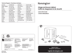
CEILING MOUNT
Ill.
QUICK STAND™ #40-SWHP, #40-SWHP-A, #40-SWHP-M
QUICK STAND™ #50-SWHP, #50-SWHP-A, #50-SWHP-M
CEILING MOUNT INSTRUCTIONS
1. Install anchors & hanger rods to overhead structure, using
appropriate hardware. (Use template printed on back of box
(See Page 2).
2. On models with PVC drain body, assemble plastic fitting,
gasket and conduit nut into large drain hole in pan, selecting
either the threaded or slip end to be outside the pan for later
drain line attachment. Always place rubber gasket between the
fitting and the metal pan for proper seal. (Fig #2)
3.
Fig #2
Install four item 'M' washers and four item 'L' nuts onto support
rods at desired height. Insert all four rods item 'R' through
platform corner brackets and raise platform to meet nut and
washer at desired height. Level platform carefully and support in
place while installing four item 'M' washers and four item 'L' nuts
onto support rods below platform corner brackets. (Fig #3)
(If Steps 6 & 7 apply, install 2 ea. of item 'L' and 'M' at
appropriate height on all four item 'R' rods)
4. Tighten all hardware.
1
I•
jl
II
'R' All Th,..d
~~~
J
••
I
5. Place water heater/equipment on platform, orienting to provide
proper access to controls and connections.
Steps 6 - 9 are for seismic zones use only
(Models #40-SWHP, #50-SWHP)
6. On seismic models, assemble the pair of item 'T' cross braces
like an "X", so notches in center interlock. (Fig #4)
7. Lay assembly on top of water heater, pulling cross brace
assembly down snugly against top of water heater (Fig #5)
(If T &P relief valve is centered at the top of the water
heater, install the T &P relief valve through the hole
provided at the intersection of the cross braces.)
8.
If permitted by water heater manufacturer, secure cross brace
assembly to top of water heater using #1 0 X 3/4" to 1" (max)
sheet metal screws.
9.
Install seismic or sway bracing as required. Attach "installer
provided" seismic hardware to the corners of the platform and
appropriate structural anchorage.
10. Install and route drain line as required.
IV.
WALL MOUNT
(Concrete Only)
QUICK STAND™ #40-SWHP-W, #40-SWHP-WM
QUICK STAND™ #50-SWHP-W, #50-SWHP-WM
WALL MOUNT INSTRUCTIONS
1.
Cut-out template printed on box, tape it to the wall in desired
location and mark the four anchor locations on wall.
2.
Drill four holes in concrete wall to the recommended depth
specified by the anchor manufacturer (use 3/8" dia. anchors rated
for the weight of this platform).
3.
Install and tighten item '0' concrete anchors. Allow min. 5/8"
of threads exposed. (Fig #1)
4.
Affix item 'J' 45° Brackets (4) to ends of both 3/8" threaded
rods item 'Q'. (Fig #2)
5.
Affix one rod assembly to each of the two upper concrete wall
anchors (finger tighten concrete anchor nuts & washers). (Fig #3)
6.
Affix set of item 'K' brackets to the two lower anchors.
The orientation of the slots in the brackets must be
horizontal and face each other. (Fig #4)
7.
'J' Bracket
Fig #1
'Q' All Thread
/
Fig #3
Position platform in lower set of item 'K' brackets, aligning the hole
of the drain pan's corner brackets with the slots in item 'K' brackets.
(Fig #5)
7.1. Slide item 'N' carriage bolts up through rear corner holes of drain
pan and through item 'K' brackets. Install item 'C' washers and item
'D' nuts on each bolt and tighten. (Fig #5)
8.
/
Fig #5
Fig #4
Align item 'J' brackets with the holes in the front corner brackets
of the platform.
8.1. Slide item 'N' carriage bolt bottom up through front corner holes of
drain pan, and slide item 'C' washer on bolt shaft and hand tighten
item 'D' flanged nuts. (Fig #6)
9.
Tighten the flanged nuts at the four corners of the platform and the
nuts at each wall anchor.
9.1. Tighten all hardware securely (If vibrating equipment will be
mounted, Loctite® or similar is recommended)
10.
On platform versions with a plastic drain assembly, install
drain fitting. Always place rubber gasket between the fitting
and the metal pan for proper seal. (Fig #7)
11.
Set water heater on platform.
11.1. In seismic regions, install QUICK STRAP® earthquake
restraint kit around water heater per manufacturer's
instructions.
Completed
Installation
Fig #6
WALL MOUNT - (Wood/Metal Studs)
v.
QUICK STAND™ #40-SWHP-W, #40-SWHP-WM, #50-SWHP-W, #50-SWHP-WM
ROUGH-IN APPLICATION ONLY
(Where Wood Backing Will Be Installed)
1.
2.
Select desired location for wall mount platform (MUST BE 16" CENTER STUD SPACING MAXIMUM).
Install 2 X 6 wood backing between studs covering at least two stud bays, in upper and lower locations. Place wood backing at face of
wall in contact with drywall. (See Fig #1)
2.1. For Wood framed walls only; Use minimum three 16- P nails at each end of each piece of wood backing (2x with fasteners staggered
and evenly spaced) through studs.
2.2. For Metal framed walls only; Use minimum five #1 0 - 1 Y:z'' coarse thread screws at each end of each piece of wood backing
(2x with fasteners staggered and evenly spaced) through studs.
2.3. For wood frame walls, secure blind end of 2 x 6 wood backing by toenailing 4 fasteners into each wood backing, 1 into top, 1 into
bottom and 2 through front at 45" angle.
3.
Verify drywall install is per Building Code, regarding fastener spacing and pattern.
AFTER DRYWALL IS INSTALLED OVER STUDS AND WOOD BACKING:
4.
Locate the wood backing previously installed in the wall using a 'stud finder' or another preferred method (make appropriate markings
on the wall to show locations of concealed backing).
5.
Use template printed on bottom of platform box to mark the four template anchor lay-out points at centerline of 2 X 6 backing. (See Fig #2A)
6.
Install four item 'P\ mounting brackets at the locations identified in step 5 above using two lag bolts item 'E' and two washers item 'C' for
each bracket. (See Fig #28)
6.1. Drill %"pilot hole for each lag bolt to avoid splitting 2 X 6 wood backing (8 locations).
6.2. Install and hand-tighten item 'B' Hex screw through center of each bracket 'P\. (See Fig #3)
6.3. Use two item 'E' Lag Bolts and item 'C' Washers to attach each mounting bracket '/J\ to wood backing through drywall
(See Fig #4A and #48)
7.
Affix 45" Brackets 'J' (4) to ends of both 3/8" threaded rods item 'Q'. (See Fig #5)
8.
Affix one rod assembly to each of the upper two Hex screws item 'B' under nut and washer 'C' and 'D'.
9.
Tighten all hardware securely (If vibrating equipment will be mounted, Loctite® or similar is recommended)
10.
Refer to steps 6 thru 11 on page 5 (CONCRETE - Steps 6-11) to complete the platform installation.
Fig #1
ANCHOR CENTER POINTS
21·7/8" (#40-SWHP-Wor ·WM}
27-3/32" (#50-SWHP-Wor -WM}
WOOD OR METAL STUDS
v··
·:··
~~..~~· %~NJ~~A~~rUM
·:··
.,v
DRYWALL
---+c:::::,
\ I
I
~B OX TEMPLATE ANCHOR
2" X 6" WOOD BACKING, 4 PLACES
(DOUGLAS FIR #2 OR BETTER}
LAYOUT POINTS (4 PLACES)
r---------r----1--_,
/------
--{-+-
--+-I
-,,, ___
23-5/8" (#40-SWHP-W or -WM}
28-718" (#50-SWHP·W or ·WM}
I
1---,---+++----~
.\•
1•:-
,;
_)
1/4" PILOT HOLES (2 PLACES)
I~
Fig #2A
I
Fig #28
(4PLACES)
A
Fig #5
Fig #3
Fig #48
(4PLACES)
VI.
WALL MOUNT - (Wood/Metal Studs)
QUICK STAND™ #40-SWHP-W, #40-SWHP-WM, #50-SWHP-W, #50-SWHP-WM
FINISH WALL MOUNT ONLY
(Where No Backing is Installed)
1.
2.
3.
3.1.
4.
4.1.
4.2.
4.3.
5.
5.1.
6.
6.1.
6.2.
7.
8.
9.
10.
11.
12.
Select desired location for wall mount platform (STUDS MUST BE 16" CENTER SPACING MAXIMUM).
Use template printed on bottom of platform box to mark four attachments points on wall surface; verify that template is held level
when making marks. (See Fig #6A}
Use box template lay-out marks (step 2 above) to draw upper and lower horizontal lines on wall surface. (See Fig #6A}
Lines must span completely across three studs (16" center stud spacing maximum).
Locate the center line of each wood or metal stud, mark intersection point with horizontal lines. Six center points must be located two on each of three studs. (See Fig #68)
On either Wood or Metal Stud Framing drill W' pilot holes in 12 locations (2 for each of 6 item 'P\ brackets). (See Fig #6A and #68}
On Metal Framed Walls Only- Using Y4" pilot holes as guides (from step 4.1 above), drill%" holes to accept Toggler® Bolts
(item 'F1') in 121ocations. (See Fig #68}
On Metal Framed Walls Only- Install 12 Toggler® bolt items 'F1' in the %" holes. (See Fig #7A and #78}
Pre-assemble three item 'P\ brackets to each of two item 'G' Unistrut Channels (channels must be 36" minimum length) using
hardware items 'C', 'D' and 'H'. (See Fig #SA and #88)
Build two Fig #8A assemblies (Only hand-tighten these hardware components at this point)
Mount both the upper and lower unistrut assemblies to the wall. (See Fig #9}
For Wood Framed Walls Only- Use lag bolt item 'E' (12 ea.) and washer item 'C' (12 ea.)
For Metal Framed Walls Only- Use Toggler® Bolt item 'F2' (12 ea.) and washer item 'C' (12 ea.)
Tighten all hardware securely (If vibrating equipment will be mounted, Loctite® or similar is recommended)
Locate the four equipment platform mounting locations and mark these onto the Unistrut® assemblies.
(See Fig #10A for locations or use the box template}
Install the four Unistrut® channel studs, item 'H' in the locations located in step 8 above using items '1', 'C' and 'D'. (See Fig #108}
Affix 45° Brackets 'J' (4) to ends of both 3/8" threaded rods item 'Q'. (See Fig #11}
Affix one rod assembly to each of the upper two Strut Channel Studs item 'H' and Suspension Washer item 'I' under nut and washer 'C' & 'D'.
Refer to steps 6 thru 11 on page 5 (CONCRETE - Steps 6-11) to complete the platform installation.
DRAW LINES ON WALL SURFACE (LEVEL)
16"" ON CENTER STUDS
NOTE: INSTALL TOGGLER® BOLT
3/8"'-16 PER MANUFACTURER'S
INSTRUCTIONS.
BOX TEMPLATE ANCHOR
LAYOUT POINTS (4 PLACES)
314" DIAMETER
~~oot::JY
STEP 4.1
WOOD OR METAL STUDS
DRILL 114"' PILOT HOLES (2 PLACES)
Fig #7B
Fig #6A
STEP4.2
Fig #6B
Fig #7A
METAL STUDS ONLY
DRILL 3/4" THROUGH DRYWALL
AND METAL STUDS (2 PLACES)
Suspension Washer Assembly, 4 Places
(&PLACES)
Fig #8A
Fig #11
Fig #10A
Fig #8B
(&PLACES)
Fig #108
II
#LT12 - 11/11