1
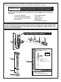
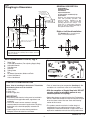
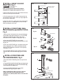
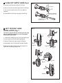
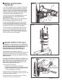
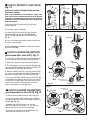
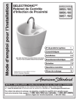
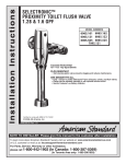
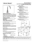
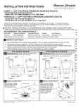
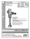
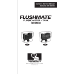
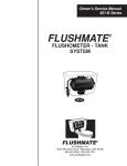
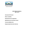
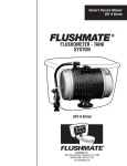
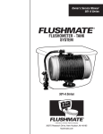
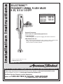
I n s t a l l a t i o n I n s t ru c t i o n s
SELECTRONIC™
PROXIMITY URINAL FLUSH VALVE
0.25, 0.5 & 1.0 GPF
MODEL NUMBERS
6063.025
6063.510
6063.505
6062.601
6063.051
6063.101
7093.051
Exposed Flushometer
for 3/4" and (1-1/4" 6062.601)Top Spud Urinals
CLOG RESISTANT
• Self-cleaning piston valve prevents clogging and reduces maintenance.
ONE SENSOR FITS ALL
• Only 1 sensor for entire Selectronic™ line of faucets, urinals, and flush valves.
• Range can be adjusted manually or with optional remote control.
• Sensor Features Low Battery Indicator.
Certified to comply with ASME A112.19.2M
© 2008 AS America, Inc.
M968567 Rev. 1.18
NOTE TO INSTALLER: Please give this manual to the customer after installation.
To learn more about American Standard Faucets visit our website at: www.americanstandard-us.com
or U.S. customer's e-mail us at: [email protected]
For Parts, Service, Warranty or other Assistance,
please call 1-800-442-1902 (In Canada: 1-800-387-0369)
(In Toronto
Toronto Area
Area only:
only: 1-905-3061093)
1-905-3061093)
(In
Thank you for selecting American-Standard...the benchmark of fine quality for over 100 years.To ensure that your
installation proceeds smoothly--please read these instructions carefully before you begin.
UNPACKING
All American Standard Products Are Water Tested At Our Factory.
Some Residual Water May Remain In The Valve During Shipping.
1. Remove the Flush Valve items from the carton. The illustration below shows all items after
they have been removed from the carton. Some items may be packaged partially assembled to
other items.
1. Flush Valve Assembly
5. Sweat Solder Adapter
2. Down Tube and Vacuum Breaker
6. Cover Tube
3. Spud Coupling Nut and Washers
7. Wall Escutcheon
4. Spud Flange
8. Supply Stop
9. Installation Instructions
CARE INSTRUCTIONS:
DO: SIMPLY RINSE THE PRODUCT CLEAN WITH CLEAR WATER. DRY WITH A SOFT COTTON FLANNEL CLOTH.
DO NOT: DO NOT CLEAN THE PRODUCT WITH SOAPS, ACID, POLISH, ABRASIVES, HARSH CLEANERS, OR A
CLOTH WITH A COARSE SURFACE.
DO NOT REMOVE PROTECTIVE FILM FROM SENSOR
EYE UNTIL INSTALLATION IS COMPLETE.
6
5
8
7
I n s t a l l a t i o n I n s t ru c t i o n s
1
2
9
3
SELECTRONIC™
PROXIMITY URINAL FLUSH VALVE
0.25, 0.5 & 1.0 GPF
MODEL NUMBERS
6063.025
6063.510
6063.505
6062.601
6063.051
6063.101
7093.051
Exposed Flushometer
for 3/4" and (1-1/4" 6062.601)Top Spud Urinals
CLOG RESISTANT
• Self-cleaning piston valve prevents clogging and reduces maintenance.
ONE SENSOR FITS ALL
• Only 1 sensor for entire Selectronic™ line of faucets, urinals, and flush valves.
• Range can be adjusted manually or with optional remote control.
• Sensor Features Low Battery Indicator.
Certified to comply with ASME A112.19.2M
© 2008 AS America, Inc.
M968567 Rev. 1.18
NOTE TO INSTALLER: Please give this manual to the customer after installation.
To learn more about American Standard Faucets visit our website at: www.americanstandard-us.com
or U.S. customer's e-mail us at: [email protected]
For Parts, Service, Warranty or other Assistance,
please call 1-800-442-1902 (In Canada: 1-800-387-0369)
(In Toronto
Toronto Area
Area only:
only: 1-905-3061093)
1-905-3061093)
(In
4
1
M968567 Rev.1.18
Fig. 1
GENERAL DESCRIPTION:
Roughing-in Dimensions
SELECTRONIC™
PROXIMITY URINAL
FLUSH VALVE
DETECTION ZONE
400mm-800mm
(15-3/4 TO 31-1/2)
72mm
(2-7/8)
FINISHED WALL
57mm
(2-1/4 MIN.)
15˚
116mm
(4-5/8)
MANUAL
OVERRIDE
BUTTON
SUPPLY
DN 19mm
(3/4” I.P.S.)
*CRITICAL
LEVEL
Right or Left Hand Installation
See (Section 5) for converting Flush
Valve to Left Hand Installation.
-C-L-
115mm-134mm
(4-1/2 TO 5-1/4)
409mm
(16-1/8)
293mm
(11-1/2)
165mm
(6-1/2)
Exposed Flushometer
for 3/4" and (1/1-4" 6062.601) Top
Spud Fixtures
Exclusive, self cleaning piston-type flush
valve with proximity operation and
manual override. Operates on DC
(b a tte r y ) p owe r. Re c o m m e n d e d
operating pressure 35 to 80 psi. Can
install left or right-handed. Detection
Zone can also be adjusted manually, or
with optional remote control.
FOR 3/4" and (1/1-4" 6062.601)
TOP SPUD FIXTURES
*Note: The Critical Line (-C-L-) on Vacuum Breaker
must typically be 6 " (152mm) above fixture. Consult
Codes for details.
RECOMMENDED TOOLS; Fig. 2
1.
2.
3.
4.
5.
6.
7.
8.
9.
10.
Fig. 2
Teflon Tape
Flat Blade Screwdriver (For adjusting Supply Stop)
Adjustable Wrench
Tape Measure
Hacksaw
Tubing Cutter
File
For Sweat Connection; Solder and Torch
2.5mm Hex Wrench
1.5mm Hex Wrench
2
1
3
4
10'
6
5
7
9
8
10
PRIOR TO INSTALLATION
Note: Prior to installing the Selectronic™Flush Valve
the following items must be installed.
1. Water Closet
2. Drain line
3. Water supply line
• Flush all water lines prior to operation (See Step 6). Dirt
and debris can cause flush valve to run continuously.
• With the exception of Supply Stop Inlet, DO NOT
use pipe sealant or plumbing grease on any
valve component or coupling!
IMPORTANT:
• Protect the chrome or special finish on the Flushometer.
DO NOT USE toothed tools on finished surfaces to install
or service these valves. Also see “Care and Cleaning”
section of this manual.
• All plumbing and electrical wiring must be installed in
accordance with applicable codes, regulations and
standards.
• The use of water hammer arrestors is strongly
recommended for commercial applications. All piping
behind the walls should be properly secured and
fastened.
• Water supply lines must be sized to provide an
adequate volume of water for each fixture.
• This product contains mechanical and/or electrical
components that are subject to normal wear. These
components should be checked on a regular basis and
replaced as needed to maintain the valve’s performance.
2
M968567 Rev.1.18
1 INSTALL SWEAT SOLDER
ADAPTER; Fig. 3
CAUTION
Fig.3
Fig.3a
FINISHED WALL
Turn water supplies off
before beginning
A
Note: Install Optional Sweat Solder Adapter
(Supplied) for copper pipe supply line. Fig. 3.
(A-B)=
C
1. Measure the distance (A) from the finished wall to the
center of the inlet spud on the fixture.
B
CENTER LINE OF
FIXTURE SPUD
32mm
(1-1/4)
FILE EDGES
2. Cut the supply pipe 1-1/4" (A-B=C) shorter then the
measurement taken in Step 1. File any rough edges off
the end of the supply pipe.
CLEAN
ADAPTER
3. Clean the end of the supply pipe. Push the threaded
Adapter on until it is seated against the internal stop.
Sweat the Adapter to the pipe.
SOLDER
ADAPTER
2 INSTALL COVER TUBE, WALL
ESCUTCHEON and SUPPLY STOP;
Fig. 4
1. Measure from finished wall to first thread of Adapter
or threaded supply pipe (dimension “X”). Cut COVER
TUBE (1) to length (X). Apply Teflon Tape to the
threaded end of the Adapter or supply pipe. Fig. 4a.
Fig. 4
FINISHED WALL
X
Fig. 4a
TEFLON TAPE
2
Fig. 4b
2. Push the COVER TUBE (1) into the WALL
ESCUTCHEON (2). Slide both onto the SUPPLY PIPE
(3). Fig. 4b.
3
2
3. Push the COVER TUBE (1) in to expose the threads
of the supply pipe. Fig. 4c. With a wrench thread the
SUPPLY STOP (4) onto the SUPPLY PIPE (3). Align
and tighten. Fig. 4c.
4. Pull COVER TUBE (1) against SUPPLY STOP (4)
and push WALL ESCUTCHEON (2) against finished
wall.
1
X
4
Fig. 4c
1
Fig. 5
3 INSTALL DOWN TUBE AND
VACUUM BREAKER; Fig. 5
5
1. Place the SPUD FLANGE (1) over the spud on the
Fixture.
2. Thread SPUD COUPLING NUT (2) onto Spud. Make
sure SEAL WASHER (3) and FRICTION WASHER (4)
are installed. Do not tighten fully.
3. Insert the DOWN TUBE (5) into the SPUD
COUPLING NUT (2) and push it down.
2
Note: If cutting Down Tube (5) to size, note that
Critical Line (C/L) on Vacuum Breaker must
typically be 6" (152mm) above fixture. Consult Code
for details.
1
3
3
4
3/4" TOP SPUD
M968567 Rev.1.18
4 FLUSH OUT SUPPLY LINES; Fig. 6
Fig. 6
2
1. Remove COVER (1) from SUPPLY STOP (2).
REMOVE COVER
2. With a flat blade screwdriver open SUPPLY STOP (2).
1
3. Turn on water supply to flush line of any debris or
sediment.
2
4. Close SUPPLY STOP (2) and replace COVER (1).
COUNTER-CLOCKWISE
OPENS CONTROL STOP
CLOCKWISE CLOSES
CONTROL STOP
453 LEFT OR RIGHT HAND
INSTALLATION; Fig. 7
Fig. 7
2
The UNIT is shipped with the inlet flange on the right
side. If needed, the orientation can be reversed by
following the steps below.
2
1
1. Loosen SET SCREW (1) with 2.5mm Hex Wrench (4)
in back of top half of FLUSH VALVE (2). Fig. 7a.
2. Rotate TOP (2) to the right and pull off. Fig. 7b.
3. Rotate bottom half of FLUSH VALVE (3) 180˚. Fig. 7b.
4
4. Replace TOP (2) and rotate until key engages than
tighten SET SCREW (1). Fig. 7c, 7d.
Fig. 7a
3
Fig. 7b
180˚
2
KEY
Fig. 7c
4 1
Fig. 7d
4
M968567 Rev.1.18
6 INSTALL FLUSH VALVE;
Fig. 8a & 8b
Fig. 8a
3
1. As shown in Fig. 8a, insert the side INLET FLANGE (1)
on the FLUSH VALVE (2) into the SUPPLY STOP (3).
Lubricate the INLET FLANGE O-RING (4) with water if
necessary. Lightly tighten COUPLING NUT (5). Fig. 8a.
Important: Do not use lubricants (other than water)
or any type of thread sealing paste or tape.
2. Align the FLUSH VALVE (2) (Fig. 8b) directly above
the DOWN TUBE (7) and VACUUM BREAKER
COUPLING NUT (6).
Note: There is a +13mm, -6mm (+1/2, -1/4) tolerance
for the 121mm (4-3/4) dimension. Fig. 8b.
3. Pull the DOWN TUBE (7) up to meet the threaded
FLUSH VALVE CONNECTION (8) and hand tighten
the VACUUM BREAKER COUPLING NUT (6). Align all
components of the flush valve assembly. Fig. 8b.
1
2
Fig. 8b
4
5
121mm,+13mm, -6mm
(4-3/4)(+1/2, -1/4)
4. Lightly tighten the COUPLING NUT (5) connection
first, then the VACUUM BREAKER COUPLING NUT
(6) and finally the SPUD COUPLING NUT (9). Once
alligned correctly, use a wrench to tighten couplings to
make water tight connections. Fig. 8b.
5
2
8
6
7 ADJUST SUPPLY STOP; Fig. 9
7
IMPORTANT: To avoid overflowing, the SUPPLY STOP
(3) must never be opened to the point where the flow
from the valve exceeds the flow capacity of the
fixture. The fixture must be able to handle a
continuous flow in case of a flush valve failure.
9
1. After installation is complete, peel off the
PROTECTIVE FILM (1) from the sensor. Standing to one
side, block the sensor with your hand for 10 seconds.
Remove your hand and listen for audible “click” from
within the valve.
2. Remove COVER (2) from SUPPLY STOP (3).Turn on
water supply 1/4 turn to 1/2 turn(CCW) and test for leaks.
Note: Unit may flush for approximately 5 to 10 sec.
when water is first turned on. If flow persists, turn
water off and repeat step #1 above.
Fig. 9
3. Actuate the FLUSH VALVE:
A) Cover sensor with hand for 10 seconds.
NOTE: Stand outside of sensor detection aera.
B) Remove hand from in front of the sensor; unit will
flush in approximately 3 seconds.
1
REMOVE COVER
3
2
COUNTER-CLOCKWISE
OPENS CONTROL STOP
4. Adjust SUPPLY STOP (3) after each flush until the
stated flush volume is achieved, no splashing occurs and
the fixture is properly cleansed.
CLOCKWISE CLOSES
CONTROL STOP
5. When adjustment is complete, replace COVER (2)
and tighten to ensure vandal-resistance.
5
M968567 Rev.1.18
8 HOW TO RETROFIT OUR VALVE;
Fig. 10
Fig. 10a
Fig. 10
6
(Replaces Industry Standard Manual and
Electronic Valves)
2
CLEAN
CONNECTIONS
1
Note: In most Retrofits the wall escutcheon, supply stop,
cover tube and vacuum breaker do not have to be replaced.
If these items do need replacement they must be purchased
separately or order the complete flush valve assembly from
American Standard.
Fig. 10b
4
5
3
1. Remove COVER (1) from SUPPLY STOP (2) if
installed. Fig. 10.
2. Turn water supply off. Fig. 10.
3. Loosen SPUD COUPLING NUT (3). Unthread
COUPLING NUT (4) and VACUUM BREAKER
COUPLING NUT (5). Remove FLUSH VALVE (6).
Fig. 10.
Fig. 11
Fig. 11a
Fig. 11b
1
3
4. Clean all threaded connections before installing the
new flush valve. Fig. 10a.
5. Refer to Sections 5,6 and 7 to complete the retrofit
installation. Fig. 10b.
2
9 HOW TO CHANGE THE BATTERY;
(purchased after June 2013) Fig. 11
1. Loosen SET SCREW (1) with 2.5mm Hex Wrench (2)
in back of top half of FLUSH VALVE CAP (3). Fig. 11a.
2. Rotate CAP (3) to the right and pull off. Fig. 11b.
3. Turn CAP (3) over and disconnect the SENSOR (4)
from the BATTERY CABLE (5). Remove the BATTERY
HOLDER (6) with BATTERY (7). Fig. 11c.
3
4. Remove old BATTERY (7). Install the new BATTERY
(8) making sure the shape of the BATTERY (8) follows
the shape of the BATTERY HOLDER (6). Fig. 11d.
6
6
4
5. Insert the BATTERY HOLDER (6) with BATTERY (8)
into FLUSH VALVE CAP (3). Make sure the flat side of
the BATTERY HOLDER (6) is facing towards the back
of the FLUSH VALVE CAP (3). Reverse the above
steps to assemble flush valve. Fig. 11d.
5
REMOVE OLD
BATTERY
-P2
CR
7
-P2
CR
INSTALL NEW
BATTERY
Fig. 11d
Fig. 11c
8
Fig. 12
9a HOW TO CHANGE THE BATTERY;
(purchased before June 2013) Fig.12
3
Fig. 12a
REMOVE OLD
BATTERY
6a
Fig. 12b
10
1. Remove CAP (3). Refer to Step 9 above. Fig. 11a.
2. Turn CAP (3) over and remove the two SCREWS
(9). Remove the BATTERY COVER (10) to expose the
battery (6a). Fig. 12a.
3. Remove old BATTERY (6a). Install the new
BATTERY (7a) making sure the + & - are facing up
towards the open end of the cover. Fig. 12b.
9
4. Replace the BATTERY COVER (10) reverse the
above steps to assemble flush valve.
7a
6
6
INSTALL NEW
BATTERY
10
M968567 Rev.1.18
11 HOW TO SET DETECTION RANGE
10
(If Required); (purchased after June 2013)
Fig. 13
Fig. 13 & 14
Note: The detection distance is preset and is ideal for
most installations. Should an adjustment be required
follow the steps below.
6
Fig. 13b
Fig. 13a
3
1. Loosen SET SCREW (1) with 2.5mm Hex Wrench (2)
in back of top half of FLUSH VALVE (3). Fig. 13a.
1
VIEW “A”
2. Rotate CAP (3) to the right and pull off. Fig. 13b.
3. Turn CAP (3) over and disconnect SENSOR CABLE
(4) from BATTERY HOLDER (5). Fig. 13c.
2
4. Keeping hands away from the front of the sensor,
reconnect the SENSOR CABLE (4) and quickly place
the CAP (3) on the valve. Do not secure the CAP (3) at
this time. Note: You have 5 seconds after connecting
cable to enter program code.
5. While the SENSOR CONTROL LED (6) is blinking
slowly, place your hand 1 to 2 in. (30-50mm.) in front of
the sensor. Fig. 14a.
Fig. 13c
6. When the LED (6) stops blinking and stays "ON",
move your hand to the desired position from sensor
(detection zone, 1-1/2" to 31", 38 to 787mm ) and hold
in place until the LED (6) begins to blink again. Fig. 14b.
Note: Detection Zone is 1-1/2" to 31", 38 to 787mm
from sensor.
3
7. Once the SENSOR CONTROL LED (6) begins to
blink again, remove your hand from the detection zone.
When the flashing stops, the detection distance is set.
VIEW “A”
4
5
8. Replace and secure CAP (3) onto valve.
9. Actuate the FLUSH VALVE:
A) Cover sensor with hand for 10 seconds. NOTE:
Stand outside of sensor detection aera.
B) Remove hand from in front of the sensor; unit will
flush in approximately 3 seconds.
Fig. 14
6
1" - 2" (30mm - 50mm
DETECTION ZONE
38mm TO 787mm
(1-1/2 TO 31)
BLINKING LED
6
Fig. 14a
BLINKING LED
Fig. 14b
7
M968567 Rev.1.18
10a HOW TO SET DETECTION RANGE
(If Required) ; (purchased before June 2013)
Fig. 15
Fig. 15 & 16
Note: The detection distance is preset and is ideal for
most installations. Should an adjustment be required
follow the steps below.
Fig. 15a
6
Fig. 15b
3
1. Loosen SET SCREW (1) with 2.5mm Hex Wrench (2)
in back of top half of FLUSH VALVE (3). Fig. 15a.
1
2. Rotate CAP (3) to the right and pull off. Fig. 15b.
VIEW “A”
3. Turn CAP (3) over and disconnect GREY SENSOR
WIRE (4) from BATTERY COVER (5). Fig. 15c.
4. Keeping hands away from the front of the sensor,
reconnect the GREY SENSOR WIRE (4) and quickly
place the CAP (3) on the valve. Do not secure the CAP
(3) at this time. Note: You have 5 seconds after
connecting cable to enter program code.
2
5. While the SENSOR CONTROL LED (6) is blinking
slowly, place your hand 1 to 2 in. (30-50mm.) in front of
the sensor. Fig. 16a.
6. When the LED (6) stops blinking and stays "ON",
move your hand to the desired position from sensor
(detection zone, 1-1/2" to 31", 38 to 787mm ) and hold
in place until the LED (6) begins to blink again. Fig. 16b.
Note: Detection Zone is 1-1/2" to 31", 38 to 787mm
from sensor.
Fig. 15c
3
5
7. Once the SENSOR CONTROL LED (6) begins to
blink again, remove your hand from the detection zone.
When the flashing stops, the detection distance is set.
4
VIEW “A”
8. Replace and secure CAP (3) onto valve.
9. Actuate the FLUSH VALVE:
A) Cover sensor with hand for 10 seconds. NOTE:
Stand outside of sensor detection aera.
B) Remove hand from in front of the sensor; unit will
flush in approximately 3 seconds.
Fig. 16
6
1" - 2" (30mm - 50mm
DETECTION ZONE
38mm TO 787mm
(1-1/2 TO 31)
BLINKING LED
6
Fig. 16a
BLINKING LED
Fig. 16b
8
M968567 Rev.1.18
9
M968567 Rev.1.18
NO
NO
NO
YES
NO
1. CLOSE STOP VALVE,
2. REPLACE SOLENOID KIT.
3. RE-ASSEMBLE AND INSTALL UNIT.
4. OPEN STOP VALVE.
YES
TEST SENSOR. DISCONNECT
GRAY FLAT WIRE FROM BATTERY
COVER AND RE-CONNECT. SENSOR
SHOULD FLASH FOR 5 SECONDS.
DOES IT FLASH?
NO
LOOK FOR REPEATED
DOUBLE FLASH ON SENSOR
NO
YES
REPLACE SENSOR
SEE STEP 10, page 6
in manual
INSTALL NEW BATTERY
RETRY AUTO FLUSH
YES
1. COVER SENSOR FOR 10 SECONDS
2. UNCOVER SENSOR FOR 10 SECONDS.
DOES THE UNIT STOP FLUSHING?
NO
MANUAL VALVE
OBSTRUCTED.
CLOSE STOP VALVE
AND SERVICE
NO
REPLACE SOLENOID KIT
REPLACE SENSOR
REPLACE PISTON KIT
INSTALL NEW BATTERY
OPEN VALVE
PUSH MANUAL FLUSH
BUTTON; DOES IT RETURN?
UNIT IS CONTINUOUSLY FLUSHING
RETRY AUTOMATIC FLUSH;
WAS IT SUCCESSFUL?
YES
DOES THE SENSOR FLASH
FOR THE FIRST 5 SECONDS?
SEE STEP 10, page 6 in manual
INSTALL NEW BATTERY
YES
TRY MANUAL VALVE BUTTON;
WILL THE UNIT FLUSH?
NO
LOOK FOR REPEATED
DOUBLE FLASH ON SENSOR
YES
IS STOP VALVE OPEN?
UNIT DOES NOT FLUSH AT ALL
NO
YES
REPLACE BATTERY
SEE STEP 10, page 6
in manual
SEE STEP 10, page 6
in manual
BATTERY LOW;
REPLACE BATTERY
Product n ames lis te d h e re i n a re tra d e m a rk s o f A S A m e ri ca , I n c.
IN CANADA 1-800-387-0369 (TORONTO 1-905-306-1093)
Weekdays 8:00 a.m. to 7:00 p.m. EST
HOT LINE FOR HELP
For toll-free information and answers to your questions, call:
1 (800) 442-1902
Weekdays 8:00 a.m. to 6:00 p.m. EST
IN MEXICO 01-800-839-12-00
TROUBLESHOOTING FLOW CHARTS
CLOSE STOP VALVE,
REPLACE SOLENOID KIT.
RE-ASSEMBLE & INSTALL UNIT.
OPEN STOP VALVE.
NO
RETRY AUTOMATIC FLUSH.
YES
TEST SENSOR. DISCONNECT
GRAY FLAT WIRE FROM BATTERY
COVER AND RE-CONNECT. SENSOR
SHOULD FLASH FOR 5 SECONDS.
DOES IT FLASH?
NO
RETRY AUTOMATIC FLUSH.
DOES THE UNIT FLUSH?
1. COVER SENSOR FOR 10 SECONDS
2. UNCOVER SENSOR FOR 10 SECONDS.
NO
LOOK FOR REPEATED
DOUBLE FLASH ON SENSOR
UNIT WILL ONLY FLUSH MANUALLY