1
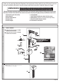
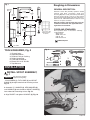
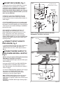
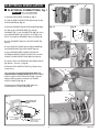
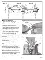
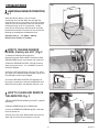
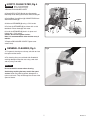
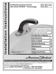
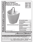
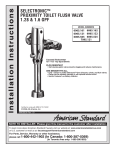
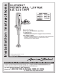
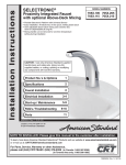
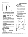
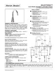
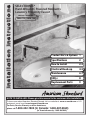
I n s t a l l a t i o n I n s t ru c t i o n s
SELECTRONIC®
Hard-Wired AC Powered Moments
Lavatory Proximity Faucet
PRODUCT NUMBERS
2506.192, 2506.195
Product No.'s & Options 1
Certified to comply with ASME A112.18.1M
© 2007 American Standard
Specifications
2
How to Install
2-3
Electrical Hook-up
4-5
Maintenance
6-7
FAQ,s
8
Replacement Parts
9
M965274
NOTE TO INSTALLER: Please give this manual to the customer after installation.
To learn more about American Standard Faucets visit our website at: www.us.amstd.com or U.S.
customer's e-mail us at: [email protected]
For Parts, Service, Warranty or other Assistance,
please call 1-800-442-1902 (In Canada: 1-800-387-0369)
(In Toronto Area only: 1-905-3061093)
Thank you for selecting American-Standard...the benchmark of fine quality for over 100 years.To ensure
that your installation proceeds smoothly--please read these instructions carefully before you begin.
UNPACKING
All American Standard Faucets Are Water Tested At Our Factory.
Some Residual Water May Remain In The Faucet During Shipping.
1. Remove the fitting and loose items from the carton. The illustration below shows the fitting and all loose items
after they have been removed from the carton. Some items may be packaged partially assembled to other items.
1. Selectronic Spout Assembly
2. Mounting Kit
3. Electrical Enclosure
4. Supply Hose
5. Power Supply
6. Circuit board
7. 10 ft. Extension Wire (for 2506.175/172 series)
8. Mixing Valve ( optional must be ordered separately)
9. Key for vandal resistant aerator
10. Installation Instructions
MODEL NUMBER:
2506.192 with cast spout, 1.5 GPM
vandal resistant aerator.
2506.195 with cast spout, 0.5 GPM
vandal resistant aerator
1
9
B
a
5
s
DO NOT REMOVE PROTECTIVE
FILM FROM SENSOR
EYE UNTIL INSTALLATION
IS COMPLETE.
e
P r o
2
d
u
c
7
t
10
3
4
I n s t a l l a t i o n I n s t ru c t i o n s
6
SELECTRONIC®
Hard-Wired AC Powered Moments
Lavatory Proximity Faucet
PRODUCT NUMBERS
2506.192, 2506.195
Product No.'s & Options 1
Certified to comply with ASME A112.18.1M
© 2007 American Standard
Specifications
2
How to Install
2-3
Electrical Hook-up
4-5
Maintenance
6-7
FAQ,s
8
Replacement Parts
9
M965274
NOTE TO INSTALLER: Please give this manual to the customer after installation.
To learn more about American Standard Faucets visit our website at: www.us.amstd.com or U.S.
customer's e-mail us at: [email protected]
For Parts, Service, Warranty or other Assistance,
please call 1-800-442-1902
(In Canada: 1-800-387-0369)
(In Toronto Area only: 1-905-3061093)
OPTIONAL Mixing Valve
605XTMV Thermostatic mixing valve, flex hoses
3/8" compression 20" hose length.
Mixing Valve
8
1
M 9 6 5 2 74
Roughing-in Dimensions
Fig. 1
FINISHED
WALL
GENERAL DESCRIPTION:
154mm
(6-1/16)
159mm
(6-1/4)
Electronic faucet with proximity operation. Vandal
resistant solid brass construction single post
mounting. Operates on AC permanent power. Water
pressure range from 20 to 125 psi. In-line strainer
for solenoid is integral. Single inlet 3/8 compression,
built-in checks, and flexible stainless steel 15" reach
inlet hose for spout connection.
126mm
(5)
55.5mm
(2-3/16)
49mm
(2)
32mm (1-1/4)
Note: All plumbing and electrical wiring must be
installed in accordance with applicable codes,
regulations and standards.
125mm
(4-7/8)
CODES AND STANDARDS:
114mm
(4-1/2)
These products meet or exceed the following
coded standards:
ANSI A117.1
ASME A112.18.1
CSA B 125
NSF 61/Section 9
ELECTRICAL BOX
OR EQUIVALENT
BY OTHERS
381mm
(15)
81mm
(3-3/16)
500mm
(20)
ADA Compliant
3/8" COMP.
TOOLS REQUIRED; Fig. 2
1
2
3
4
5
6
7
Fig. 2
Channel Locks
Adjustable Wrench
Plumbers' Putty or Caulking
Phillips Screwdriver
Flat Blade Screwdriver
Electric Drill & 1/4" Drill Bit
Tape Measure
2
1
3
7
4
6
10'
5
INSTALLATION
1 INSTALL SPOUT ASSEMBLY;
Fig. 1a
Fig. 1
CAUTION
1
Turn off hot and cold water
supplies before beginning
1. Insert WIRES (1), FLEX HOSE (2) and SPOUT
SHANK (3) through center hole of mounting surface.
Fig. 1a.
2
2. Assemble "C" WASHER (4), STAR WASHER (5)
and LOCKNUT (6) onto threads of SPOUT SHANK (7)
from underside of mounting surface. Fig. 1b.
3. Align FAUCET and tighten LOCKNUT (6). Fig. 1b.
Fig. 1b
3
7
4
6
5
2
M 9 6 5 2 74
2 MOUNT ENCLOSURE; Fig. 2
Fig. 2
1. Determine location of ENCLOSURE (1). It must be
located with-in the 14" (356mm) by 21" (533mm)
shaded area shown in Figure 2 in order for electrical
connections from the spout assembly to be made.
NOTE: ENCLOSURE SUPPLY HOSE is 20". Distance
between wall supply and ENCLOSURE (1) must be
taken into consideration.
LAVATORY RIM OR
MOUNTING SURFACE
14"
(356mm)
SUPPLIES
ENCLOSURE
MOUNTING
HOLES
1
2-3/4"
(71mm)
2. Remove 4 screws from COVER (2) and pull off
COVER (2). Hold the ENCLOSURE (1) in desired
location and mark the four mounting hole locations as
shown. Fig. 2.
WASTE
20"
(500mm)
21"
(mm)
3"
(76mm)
3-3/4"
(96mm)
MOUNTING HOLES
3. The ENCLOSURE (1) works best if secured to a wall
stud or cross brace within the wall, using the SCREWS
(3) supplied. If the ENCLOSURE (1) is to be installed on
a tile or plaster wall the ANCHORS (4) and SCREWS
(3) should be used.
3
1
2
4
1
4. For installations on drywall or tiled walls; use
ANCHORS (4) and SCREWS (3) for securing
ENCLOSURE (1) to finished wall. Drill four 1/4" dia.
holes a minimum of 1-3/4" deep. Insert the four
ANCHORS (4) flush with face of the finished wall.
Align the ENCLOSURE (1) and Install the MOUNTING
SCREWS (3). Tighten to secure ENCLOSURE (1) to
mounting surface.
NOTE: If using Mixing Valve (optional) See Sheet
#M968808 for installation instructions.
Fig. 3
3 CONNECT SPOUT HOSE TO
ENCLOSURE; Fig. 3
1
2
1. Connect SUPPLY NUT (1) from spout assembly to
nipple on top of ENCLOSURE (2). Tighten with
adjustable wrench to make a water tight connection.
Fig. 3.
4 CONNECT WATER SUPPLY TO
ENCLOSURE AND WALL SUPPLY;
Fig. 4
Fig. 4
DO NOT USE PIPE
SEALANT ON THREADS
4
3
2. Connect SUPPLY NUT (1) on ENCLOSURE (2) to
FLEXIBLE SUPPLY HOSE (3). Tighten to make a
water tight connection. Use two wrenches to tighten if
necessary. Fig. 4.
Fig. 4a
3. Connect FLEXIBLE SUPPLY (3) directly to wall supply.
Connection on FLEXIBLE SUPPLY (3) is 3/8"
compression. Use adjustable wrench to tighten
connection. Do not over tighten. Fig. 4a.
Note: FLEXIBLE SUPPLY (3) measures 20" from the
bottom of the ENCLOSURE (1) base. If additional
supply length is required, installer must purchase parts
separately.
Important: If FLEXIBLE SUPPLY (3) is too long, loop to
avoid kinking.
1
2
NOTE; If using the optional Mixing Valve See Sheet
#M968808 for installation instructions.
1. Insert FIBER WASHER (4) into SUPPLY NUT (1) on
ENCLOSURE (2).
4" ELECTRICAL BOX
OR EQUIVALENT BY
OTHERS
COLD WATER OR
TEMPERED
WALL SUPPLY
3
3
M 9 6 5 2 74
ELECTRICAL INSTALLATION
Fig. 1
1
5
1 ELECTRICAL CONNECTIONS; Fig. 1
CAUTION
4
Before opening ENCLOSURE
disconnect AC power supply.
1. Remove ENCLOSURE COVER (1). Fig. 1.
2. Feed the WIRE CONNECTORS (2) through the top
of ENCLOSURE (5). Fig. 1a.
3. Remove GROMMET (4) from ENCLOSURE (5). Fig. 1.
Fig. 1b
Fig. 1a
4"
4. Feed the gray SENSOR WIRE (7) through
GROMMET (4), 4" from CONNECTOR. Fig. 1b. Insert
gray SENSOR WIRE (7) into SPLIT PLUG (9). Push
SPLIT PLUG (9) into GROMMET (4) to seal. Fig. 1d.
5
4
7
5. Insert GROMMET (4) back into ENCLOSURE (5).
Fig. 1c.
Fig. 1c
F
6. Install CIRCUIT BOARD (3) into ENCLOSURE (5)
with SENSOR WIRE (7) under BOARD. Fig. 1c.
5
7. Insert SENSOR WIRE CONNECTOR (8) and
EXTENSION WIRE CONNECTOR (11) into available
CIRCUIT BOARD RECEPTORS (10) slots. Fig. 1e.
2
7
6
4
RED
8
BLACK
3
8. Connect wires from SENSOR to SOLENOID VALVE
(6) (Red to +, Black to -). Fig. 1d.
9. Replace ENCLOSURE COVER (1). Tighten cover
screws firmly.
Fig. 1d
9
4
10. Contractor to supply ELECTRICAL BOX (12)
and connection to ENCLOSURE (5). Mount POWER
SUPPLY (13) into ELECTRICAL BOX (12). Connect
White and Black power connections to POWER
SUPPLY CABLE (14). Fig. 1f.
7
11. Connect the EXTENSION WIRE (16) to the
POWER SUPPLY CABLE (15). FIG. 1f.
Fig. 1e
8
Fig. 1f
10
11
10
4" ELECTRICAL BOX
OR EQUIVALENT BY
OTHERS
12
16
15
14
BLACK & WHITE
POWER
CONNECTIONS
13
CONNECTOR NOT
USED IN THIS
INSTALLATION
4
M 9 6 5 2 74
Fig. 2
Unit #1
Unit #2
4
TWO PIECE
GROMMET
9
6
3
3
1
3
Unit #3
10
4
2
1
1
4"
1
1
5
2 FOR AC-VERSION
Fig. 3a
(MULTI HOOK-UP); Fig. 2, 3
TWO PIECE
GROMMET
1. See AC Version Electrical Hook-up for first unit of the
Multi hook-up.
8
7
2. Remove ENCLOSURE COVERS from all
ENCLOSURES.
3. Remove SOLID BLACK INSERT(1) from right side
of ENCLOSURE #1 and replace with gray 2-PIECE
GROMMET (3). Replace solid black inserts on Unit #2
with gray 2-PIECE GROMMET (3).
2
4. Take the 10 ft. EXTENSION (2) from Unit #2 and
install into right side of Unit #1 and Left side of Unit #2
insealing wire into SPLIT PLUG (7) as shown in Fig. 3a.
Push SPLIT PLUG (7) into GROMMET (8).
Feed the gray 8 ft. EXTENSION (2) through ROUND
GROMMETS (3) and U GROMMETS (5) as illustrated above.
5. Insert CONNECTOR from 10 ft. EXTENSION (2) into
CIRCUIT BOARD RECEPTOR (4) top of Unit #1 as
shown in Fig. 2.
Fig. 3b
6. Insert other end of 10 ft. EXTENSION into LOWER
U GROMMET (5) of Unit #2 (approximately 4" from
connector). Fig. 3. Push SPLIT PLUG (7) into
GROMMET (8) to seal.
2
1
7. Insert connector of 10 ft. EXTENSION into lower
receptor as shown in fig. 3 on CIRCUIT BOARD (6) of
Unit #2.
RED
3
8. Feed gray sensor wire 9 from Unit #2 through upper
U GROMMET (10) of Unit #2 ENCLOSURE 4" from
connector Fig. 3. Insert wire into SPLIT PLUG (7).
Push SPLIT PLUG (7) into GROMMET (8) to seal. Fig. 3a.
BLACK
9. Insert GROMMET (2) back into ENCLOSURE. Fig. 3b.
10. Reinstall Circuit Board (3) into Enclosure with all
wires under Board. Fig. 3b.
11. Connect Unit #2 Red and Black Sensor wires To #2
solenoid valve (Red to +, Black to -). Fig. 3b.
12. Repeat Steps 3 through 11 for remaining Units in
Multi Hook-up.
5
M 9 6 5 2 74
MAINTENANCE
Fig 1
DETECTION
ZONE
1 HAND WASH SENSOR OPERATION;
Fig. 1
When the Sensor detects a user, the water
immediately starts to flow. Water flow will stop Two
seconds after user is out of sensor range. The off delay
allows the user to comfortably move his hands without
the flow cycling on to off. As a precaution, a safety
timer will turn off the water, after the sensor has been
blocked for 59 seconds. The water will stay off until the
blockage is removed from the detection zone.
Detection Zone: 2" - 10" (50mm - 250mm)
Default: Set at Factory 6" (150mm)
2 HOW TO CHANGE SENSOR
Fig.
Fig. 22
RANGE; (Factory set at 6") Fig. 2
1. Setting the Detection Zone (Distance):
Remove cover from ENCLOSURE. Disconnect GRAY
SENSOR WIRE (1) from circuit board, then reconnect.
2. While the SENSOR CONTROL LED (2) is blinking
slowly, place your hand 1 - 2 in. (30-50mm) in front of
the sensor. Fig. 2a.
1
3. When the LED stops blinking and stays "ON", move
your hand to the desired position and hold in place until
the LED begins to blink again. Fig. 2a.
Fig.
Fig. 2a
2a
Fig. 2a
1" - 2" (30mm - 50mm
4. Once the SENSOR CONTROL LED (2) begins to
blink again, remove your hand from the detection zone.
When the flashing stops, the detection distance is set.
2
BLINKING LED
UP TO 10"
(250mm)
2
BLINKING LED
3 HOW TO CLEAN AND REMOVE
Fig.3
THE AERATOR; Fig. 3
1
1. Remove AERATOR HOUSING (1) with KEY supplied
with faucet.
3
3. Remove AERATOR (2) from HOUSING (1).
2. Clean the AERATOR SCREENS (3) with a old tooth
brush to remove dirt.
4. Rinse Clean with water. Reassemble and install into
spout end. Be sure black seal washer is in place.
2
6
M 9 6 5 2 74
4 HOW TO CLEAN FILTER; Fig. 4
CAUTION
Fig.4
Before opening ENCLOSURE
disconnect AC power supply.
1. Remove ENCLOSURE COVER.
2. Close SUPPLY STOP (5) with 4mm Hex wrench.
Note: Keep water flowing out of faucet while shutting off.
3
3. Pull off Red (1) and Black (2) CONNECTORS from
SOLENOID VALVE (3).
4
CLEAN
SCREENS
4. Unthread STRAINER (4) using a 7/16" socket.
5. Pull out the STRAINER (4) and clean with an old
toothbrush. Rinse thoroughly with water.
6. Install the STRAINER (4) back in its place and
tighten with a 7/16" socket.
Caution: do not over tighten strainer.
Note: It is recommended to clean strainer every 6
months.
2
1
5
4
7. Replace ENCLOSURE COVER. Tighten cover
screws firmly.
5 GENERAL CLEANING; Fig. 5
Fig.5
1. For general cleaning use a damp, soft cloth to clean
the spout and the sensor.
2. For cleaning dirt use a soft cloth with diluted dish
washing detergent. Wipe the area using a wet cloth
and dry using a soft cloth.
CAUTION
Do not scratch the sensor when cleaning.
Avoid using anything that may scratch the spout
surface. Never use polishing power, detergent or a
nylon scrub brush. They will damage the surface of the
spout or Sensor.
7
M 9 6 5 2 74
FAQ'S
Q: How will I know if battery needs to be replaced?
A: Valve does not open and sensor blinks 2 times
interrupted by pause for up to 7 days.
Q: Why does the faucet operate the opposite of
expected-Turns On when not in sensor range, but turns
off when in sensor range?
A: Sensor wires to solenoid are reversed. Black to & Red to + is correct.
Q: Why has the flow rate of the faucet reduced
significantly?
A: Check and clean aerator and strainer.
Q: What is the normal operating pressure range?
A: Faucet will operate with supply pressures ranging
from 20-80 psi.
Q: There is no flow out of faucet when I'm in the
sensor range?
A: Check sensor. If sensor blinks 2 times interrupted by
pause, replace battery, or call 1800-442-1902.
8
M 9 6 5 2 74