1
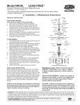
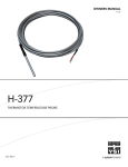
Model 500XL LEAD-FREE* Pressure Reducing Valve with Integral By-pass ® (1/2”, 3/4”, 1”, 1 1/4”, 1 1/2”, 2”, 2 1/2” & 3”) *This product contains a weighted average lead content less than 0.25% for wetted surfaces. Installation Testing Maintenance Instructions REPAIR KIT INSTRUCTIONS HOW TO MAKE REPAIRS: (Shut off service before starting disassembly) 1.Open faucet or hose bibb in dwelling to remove line pressure. 2.Loosen cap and remove counterclockwise. 3.Loosen plunger and remove counterclockwise; insert new seal ring. 4. Note distance that adjustment bolt protrudes from bell housing. Loosen locknut on adjustment bolt, then turn adjustment bolt out of bell housing to remove spring tension. 5. Unscrew bell housing counterclockwise and remove spring, spring disc and friction ring. 6. Remove stem unit from regulator. Inspect area in body where o-ring guides for pitting or scratches. Smooth bore with emery cloth if needed. This area must be smooth for the valve to function correctly. 7. Disassemble stem unit by holding stem securely while removing diaphragm bolt/nut. Discard old stem and diaphragm. Retain diaphragm disc and diaphragm bolt/nut for use on new stem. TO REASSEMBLE: 1.Open shut-off valve slowly and flush body and line of any debris. 2.Assemble new stem unit using new stem, o-ring, diaphragm, the old diaphragm disc and diaphragm bolt/nut. Tighten bolt/nut securely (CAUTION: Be sure the rounded edge of the diaphragm disc is next to the diaphragm). 3.Lubricate o-ring with grease supplied in repair kit and install stem unit in body. Install new spring, spring disc and friction ring. 4.Replace bell housing by tightening clockwise. Turn adjustment bolt clockwise until adjustment bolt touches spring disc. 5.Center washer on stem. Screw plunger into stem unit (CAUTION: Do not over tighten plunger; it is possible to break threaded end of plunger). 6.Install new cap gasket and replace cap by tightening clockwise. 7.Turn adjustment bolt into bell housing to old setting. 8.Enter dwelling and turn on several faucets. 9. Turn on water service. Let water run for several seconds then turn off faucets in dwelling. 10. Adjust the regulator to desired pressure by turning adjustment bolt clockwise (into bell housing) to raise pressure or counterclockwise (out of bell housing) to lower pressure. It is recommended a pressure gauge be installed downstream of the regulator to ensure pres- sure is reduced below 75 psi. NOTE: When reducing pressure, open a downstream faucet to relieve pressure. 11.Tighten locknut when desired pressure is achieved. INSTALLATION INSTRUCTIONS Install valve in line with arrow on valve body pointing in direction of flow. Before installing reducing valve, flush out line to remove loose dirt and scale which might damage seal ring and seat. All valves will be furnished with stock settings to reduce to approximately 50 psi. To readjust reduced pressure, loosen outer locknut and turn adjustment bolt clockwise (into bell housing) to raise reduced pressure, or counter-clockwise (out of bell housing) to lower reduced pressure. NOTICE: Annual inspection and maintenance is required of all plumbing system components. To ensure proper performance and maximum life, this product must be subject to regular inspection, testing and cleaning. ADJUSTMENT BOLT LOCKNUT SEALED CAGE WASHER NAMEPLATE BELL HOUSING *FRICTION RING (1/2"-1 1/2" only) SPRING DISC* *SPRING DIAPHRAGM BOLT/NUT DIAPHRAGM DISC DIAPHRAGM* *STEM UNION NUT *O-RING TAILPIECE 500XL UNION GASKET* SEAT GASKET WASHER* BODY SEAT *SEAL RING PLUNGER *CAP GASKET CAP * INDICATES PARTS SUPPLIED IN REPAIR KITS (spring disc not included in sizes 1 1/2" - 3") Regulators in series: Where the desired pressure reduction is more than a 4 to 1 ratio (i.e. 200psi to 50psi), multiple regulators in series should be installed. SEALED CAGE WARNING: Loosen lock washer at adjustment bolt slowly. Look for any trapped water pressure under the sealed cage washer. Relieve pressure before removing bell. CAUTION: Anytime a reducing valve is adjusted, a pressure gauge must be used downstream to verify correct pressure setting. Do not bottom out adjustment bolt on bell housing. Valve may be installed in any position. WARRANTY: ZURN WILKINS Valves are guaranteed against defects of material or workmanship when used for the services recommended. If in any recommended service, a defect develops due to material or workmanship, and the device is returned, freight prepaid, to ZURN WILKINS within 12 months from date of purchase, it will be repaired or replaced free of charge. ZURN WILKINS’ liability shall be limited to our agreement to repair or replace the valve only. Proposition 65 Warning This product contains chemicals known to the State of California to cause cancer or birth defects or other reproductive harm. ® 1 Troubleshooting Pipe lines in a water supply system must be of sufficient carrying capacity to maintain adequate pressure at the most remote or highest fixture. Under the maximum probable fixture use, minimum adequate pressure is generally 8 to 15 lbs. but may be more, depending on the equipment being supplied. Relatively high service pressures which can create high water velocities in pipe lines would allow use of smaller pipes to satisfy fixture use. However, high velocity tends to cause whistling and humming. Reduction of pressure by the use of a pressure reducing valve, in an attempt to eliminate such a condition, may reduce pipe line capacities below that which is adequate for maximum probable use. When high service pressures are in effect, either continuously or periodically, the application of a pressure reducing valve will be successful only when the installed pipe line is of adequate size to satisfy the system demand at the lower pressure. When actual water demands are unknown, the valve size should be no less then the existing pipe size. PROBLEM POSSIBLE CAUSE OR CAUSES 1. Pressure creeps or builds up in system above the setting of pressure reducing valve. SOLUTION a. b. c. d. 2. 3. a. b. c. ® IS500XL (REV. 8/13) A. B. C. Pipelines to fixtures may be too small or house main supply may be inadequate for normal fixture demand. Heavy periodic demands by appliances in the house. Screen clogged with debris. It may be necessary to increase pipe sizes only in some sections of the system leading to the offending appliances or fixtures. Increasing the house service mains might be necessary if small supply is general at all fixtures. Raise pressure gradually by readjusting valve until this point is determined. Clean screen. 4. Valve appears to be noisy; hums, whistles or chatters. SOLUTION a. b. c. A. Low water supply pressure in mains caused possibly by high area demand during certain periods of the day. B. Heavy periodic demands by appliances in the house. This is a water department problem. It is due to the mains being inadequate for the demands made on them. House service lines may at times be inadequate for the load. Size of some pipelines may need to be increased. Pressure setting of reducing valve may be too low. Try increasing pressure before changing pipelines. Small, inadequate flow from fixtures. SOLUTION Thermal expansion of water as it is being heated. Foreign matter on seating face of seal ring. Cut, worn or chipped seal ring. Cut or worn stem o-ring or worn o-ring groove. This is a natural consequence. It may happen each time that the heater runs. A pressure relief valve or expansion tank must be installed. This will not prevent pressure rise but should limit it to a safe level. Flush the reducing valve by opening one or two fixture outlets wide. If this does not correct the problem, remove seal ring for cleaning. Replace with new seal ring. Temporary repairs may be made by turning the seal ring over. Replace with new stem o-ring and/or cartridge. Pressure and fixture flow is unsteady. SOLUTION a. b. c. A. B. C. D. A. B. Hum or whistle is usually caused by a high velocity of flow in pipelines causing vibration. Chatter usually originates with worn seat washer or loosely installed seal ring. Pipelines could be small or too light. Reducing valves could be too small. Pipes and valves being small would accentuate this condition. Inspect seal ring. If a deep channel appears on seal ring face, replace or use the opposite side. Frequently noise appears in a faucet or appliance and seems to originate from the reducing valve. There is a general tendency to use streamline piping of a relatively small size. Velocity is naturally high and noise of fast moving water is not unusual. ZURN WILKINS 1747 Commerce Way, Paso Robles, CA 93446 Phone:855-663-9876 Fax:805-238-5766 www.zurn.com 2